Downloaded 369 times

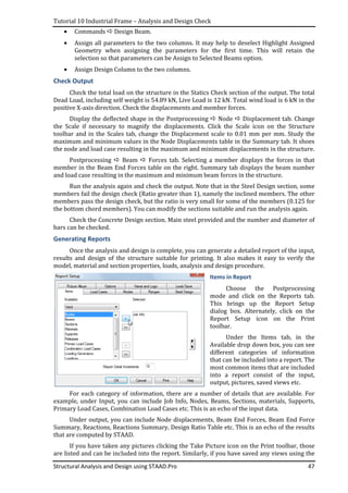
![Tutorial 1 – Terminology and Notations
Structural Analysis and Design using STAAD.Pro 3
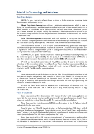
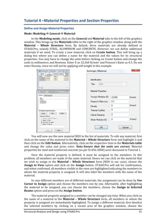
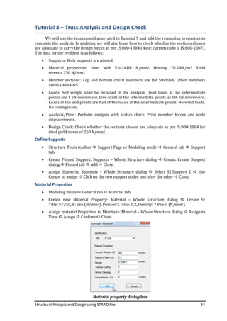
The commonly required properties are Young’s Modulus (E), Poisson’s Ratio (ߥ), Density,
Thermal coefficient (α), Critical damping and Shear modulus (G). Of these, the important one is
Young’s modulus, which is required for all analyses. Density is required if you want STAAD.Pro
to calculate self weight of members automatically. Shear modulus is required when shear
deformations are important, such as in shear walls, deep beams, plate and solid elements.
Poisson’s Ratio can be used to calculate the Shear modulus from Young’s modulus. Thermal
coefficient is required only in problems in which temperature loads are imposed. Critical
damping coefficient is required only for problems involving dynamic loads.
Further, it is important to be aware of the units being used at any given point of time and
input the material properties in the correct units. Alternatively, you can change the units
before inputting the material property values.
Material Property Steel Concrete M20 M30
1 Young’s Modulus 2 × 10ହ
N/mm2
(2 × 10଼
kN/m2)
5000ඥ݂
N/mm2
22,360 N/mm2
(2.236x10⁷ kN/m2)
27,386 N/mm2
(2.7386x10⁷ kN/m2)
2 Poisson’s Ratio 0.2 0.3
3 Density 78.5 kN/m3
(78.5x10⁻⁶ N/mm3)
25 kN/m3
(25x10–6 N/mm3)
4 Damping Ratio 2 % 5%
Unit conversion factors are as follows:
To Convert From To By
N/mm2 kN/m2 103
kN/m3 N/mm3 Multiply with 10ି
N/m3 N/mm3 10ିଽ
Stiffness Method
Most structural analysis programs are based on the matrix stiffness method, usually in
the form of the Finite Element Method. The matrix stiffness method can be represented in the
form of the stiffness equation, which is as follows:
ሾܭሿሼݔሽ = ሼܲሽ
where [K] is the stiffness matrix of the structure of size ݊ × ݊, {x} is the vector of unknown
displacements of size ݊ × 1 and {P} is the vector of known external loads corresponding to the
unknown displacements. Here, n is the number of unknown displacements. Of course, this is
only a simplistic representation, but is sufficient for a first introduction.
The stiffness equation is first solverd for the unknown displacements {x} and from the
unknown displacements, the forces in all the members of the structure can be determined. The
stiffness matrix depends on the stiffness contribution of individual members of the structure.
The stiffness matrix and load vector are expressed in global coordinate system and the
resulting displacements obtained are therefore in global coordinate system. To find the
member end forces, which are usually in local coordinate system, the displacements at the
nodes of the member are transformed from global to local coordinate system. From the
displacements at the nodes of a member, expressed in local coordinate system, the member
forces are calculated in local coordinate system.
Typical Load Calculations
In the examples we will analyse in subsequent tutorials, we will use loads whose detailed
calculations are not shown. In this section, we will describe the steps used in arriving at those
loads. The Dead Load calculations are based on densities of materials and are assumed to be
25 kN/m3 for reinforced concrete, 20 kN/m3 for brick masonry, 78.5 kN/m3 for structural steel,](https://image.slidesharecdn.com/f4bc3229-bef0-47e9-ac87-d3900adeeff4-170111053056/85/STAAD-Pro_Trg_Course_Material-6-320.jpg)
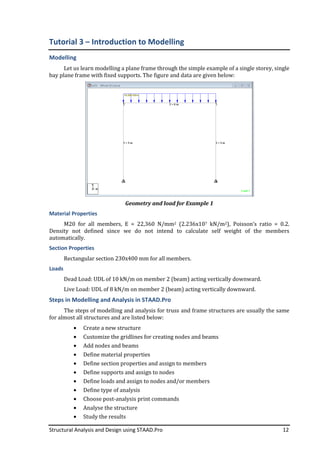
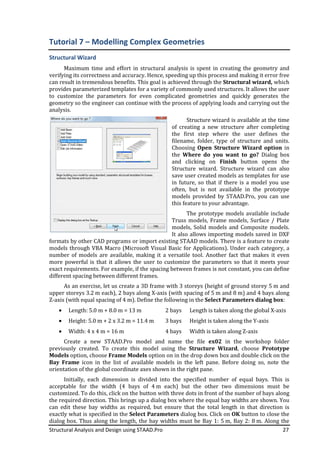
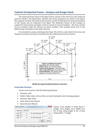

This document provides an introduction and overview of structural analysis and design using the STAAD.Pro software. It describes key terminology and concepts for modeling structures in STAAD.Pro, including coordinate systems, units of measurement, types of structures that can be modeled, types of structural members and elements, and the properties required for different member types. The goal of the training program is to teach beginners how to use the basic modeling capabilities of STAAD.Pro for linear static analysis of structures such as frames, trusses, and plates/shells.


