Downloaded 31 times

![J. Janardhan et al. Int. Journal of Engineering Research and Applications www.ijera.com
ISSN : 2248-9622, Vol. 4, Issue 12( Part 6), December 2014, pp.253-258
www.ijera.com 257|P a g e
S.No. Cycles Alternating Stress (Pa)
1 17000 2.758e+008
2 50000 2.413e+008
3 34000 2.068e+008
4 1.4e+00
5
1.724e+008
5 8.e+005 1.379e+008
6 2.4e+00
6
1.172e+008
7 5.5e+00
7
8.963e+007
8 1.e+008 8.274e+007
Table. 3.1 S-N Curve
3.8 Fatigue Results:
Fig.3.8 Fatigue Results
3.9 Result:
Name Type Scale
Facto
r
Stress
Component
Infinite
Life
Fatigue
Tool
Fully
Reversed
1.0 Signed
Von-Mises
1.0x10⁹
Table 3.2. Fatigue result
V. CONCLUSIONS AND FUTURE
SCOPE
As in the case of an automobile wheel maximum
load is applied on the alloy wheel. Analysis of the
wheel plays an important role for the safety of the
passenger cars. This project deals with the fatigue
analysis of the wheel, as explained in the previous
chapters.
The 2D of the wheel was created in MDT, the
drafting package and the same was exported to
ANSYS, the finite element package using IGES
translator where the 3D model of the wheel is
created. The wheel is meshed using SOLID 45
element. A load of 2500N was applied on the hub
area of the wheel and a pressure of 0.207N/mm2 is
applied on the outer surface of the rim. The pitch
circle holes are constrained in all degrees of
freedom. The analysis is carried under these
constraints and the results are taken to carryout for
further analysis i.e fatigue module to find the life of
the wheel. Various number of cycles the analysis has
been done. Finally we found Equivalent (Von-Mises)
Stress we find 9.205x1e6 Pa maximum stress. And
the minimum stress is 0.041x1e6 Pa. and the
deformation is observed as the 0.515x1e-1 mm after
running the fatigue cycles we found that the infinite
life at 1.0x10⁹ cycles.
Same analysis can be performed with alternate
materials by applying load at different areas on the
wheel, to reduce the weight, which ultimately
reduces the overall cost, with increase in lifetime,
and we can find the failure by changing loads by
increasing or decreasing according to our
requirements of that particular wheels we also
change the models or design of the wheel and to test
for the fatigue and comparing with the two models
which will give the more life we can identify and we
can develop that model. And also the various tests
have to be done by other two tests such as cornering
test and impact test.
REFERENCES:
[1]. J.Stearns, P.C.Lam, and T.S.Srivastsans “An
analysis of Stress and Displacement in a
Rotating Rim subjected to Pressure and
Radial Loads.” Division of Advanced
Product and Process Technology. The
Goodyear Tyre and Rubber Company,
Akron, Ohio, U S A. April 14,2000.
[2]. Smithers Scientific Services, Inc.”Wheel
Test Center”Smithers Scientific Services,
Inc. 425 West Market Street, Akron, OH
44303-2099 U.S.A. 1997
[3]. Pottinger, M.G., Arnold, G.A., Marhall,
K.D.,[1976] “The effect of test speed and
surface curvature on cornering properties of
wheel”.
[4]. Ering Tonuk, Y.samin Unlusoy [2001] ,
“Prediction of Automobile tyre cornering
force characteristics by finite element
modeling and analysis”.
[5]. Wright,D.H., [1983] “Test Method for
Automotive Wheels, Institute of Mechanical
Engineering” Paper No.c278/83,in
Automobile Wheels and Tyres.
[6]. Cameron. Lonsdale and Francois. Demility.
[1999] “Wheel Rim Residual Stress
Measurement”.
[7]. Konishi,H.,Fujiware,A.,Katsura,T.,
Takeuchi,K.,and Nakata,M., 1996,”Impact
Strength of Aluminium alloy Wheel
(Influence of Disk and Rim Rigidity on the](https://image.slidesharecdn.com/al041206253258-150115054933-conversion-gate02/85/Radial-Fatigue-Analysis-of-An-Alloy-Wheel-5-320.jpg)
![J. Janardhan et al. Int. Journal of Engineering Research and Applications www.ijera.com
ISSN : 2248-9622, Vol. 4, Issue 12( Part 6), December 2014, pp.253-258
www.ijera.com 258|P a g e
JWL Impact Strength of Aluminium alloy
Wheel)”Nippon Kikai Gakkai
Ronbunshu,C.Hen,Vol.62,n 599,pg. 2884-
2890.
[8]. Mizoguchi, T., Nishimura, H., Nakata, K.,
and Kawakami, J., 1982, “Stress Analysis
and Fatigue Strength Evalution of Sheet
Fabricated 2-Piece Aluminium alloy Wheels
for Passenger Cars.”R&D,Reserch &
Development (Kobe Steel, Ltd),Vol.32,n
2,pg.25-28.
[9]. Konishi,H.,Fujiwara,A.,Katsura, T.,
Takeuchi,K.,and Nakata,M.,[1997],”Impact
Strength of Aluminium alloy Disk Wheel”
Nippon Kikai Gakkai
Ronbunshu,R&D,Reserch & Development
(Kobe Steel, Ltd), Vol 47, n 2,pp.25-28.
[10]. Fischer, G.; Grubisic, V.: Biaxial Wheel /
Hub Test Facility, Proceedings of the 4th
International User Meeting,September 21
st,1999 in Darmstadt LBF-Report No.TB-
219[2000].
[11]. Rupp, A., Grubisic, V.: Reliable and
Efficient Measurement of Suspension Loads
on Passenger-cars and Commercial Vehicles
International Conference and Exibition,
Ancona, 29.-30.6.1995.ATA
Orbassano[1995], s. 263-273.
[12]. Best Cast IT Ltd, “Reference Manuals” for
data on alloy.
[13]. Alfredsson, B. and Cadario, A., To appear
in: Int J Fatigue.
[14]. Chandawanich, N. and Sharpe, W. Jr., “An
Experimental Study of Fatigue Crack Growth
Initiation and Growth from Cold worked
Holes,” Engineering Fracture
Mechanics,Vol. 11, 1979, pp. 609-620.
[15]. Cathey, W. H. and Grandt, A. F., “Fracture
Mechanics Consideration of Residual
Stresses Introduced by Cold working
Fastener Holes,” Journal of Engineering
Materials and Technology, Vol. 102,
1980,pp. 85-91.
[16]. Fuchs, H.O. and Stephens, R.I. (1980) Metal
Fatigue in Structures. New York: John Wiley
and Sons.24.Gavin, H.P. (1986) “Spoked
Bicycle Wheels: A Comparative
Experimental and Finite Element Analysis of
Static and Dynamic Characteristics of
Bicycle Wheels with Variable Spoking
Patterns.” Undergraduate Leve, Howard L.
(1969) “Cumulative Damage Theories.” in
Metal Fatigue: Theory and Design. A.F.
[17]. Pippard, A.J.S., and Francis, W.E. (1931)
“The stresses in a radially-spoked wire wheel
under loads applied to the rim.”
Philosophical Magazine, 7(11), 233-285.
[18]. Pippard, A.J.S., and Francis, W.E. (1932)
“The stresses in a wire wheel under side
loads on the rim.”
[19]. Pippard, A.J.S., and White, M.J. (1932)
“The stresses in a wire wheel with non-radial
spokes under loads applied to the rim.”
Philosophical Mag., 7(14), 209-233.
[20]. Pope, Joseph Albert. (1959) Metal Fatigue.
London: Chapman and Hall.Price, D. and
Akers, A. (1985) “Stiffness Characteristics
of Bicycle Wheels.” Bike Tech. Emaus, PA:
[21]. Rice, Richard C. (1985) “Fatigue Data
Analysis.” in Metals Handbook. 9th Edition,
Vol. 8 (Mechanical Testing), Metals Park,
Ohio: American Society for Metals.](https://image.slidesharecdn.com/al041206253258-150115054933-conversion-gate02/85/Radial-Fatigue-Analysis-of-An-Alloy-Wheel-6-320.jpg)

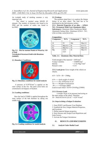
This document presents a radial fatigue analysis of an aluminum alloy wheel, detailing the modeling process using MDT and ANSYS software to evaluate fatigue life under dynamic loads. Key findings include the application of a 2500 N load and pressure of 0.207 N/mm², resulting in an infinite life at 1.0 x 10^9 cycles with maximum and minimum equivalent stresses of 9.205 x 10^6 Pa and 0.041 x 10^6 Pa, respectively. Future work suggests exploring alternate materials and designs to enhance strength and longevity while reducing weight and cost.


![[IJET V2I5P11] Authors: P. R. SHINDE , Dr. K. B. KALE](https://cdn.slidesharecdn.com/ss_thumbnails/ijet-v2i5p11-161107141523-thumbnail.jpg?width=640&height=640&fit=bounds)


