Download as PDF, PPTX

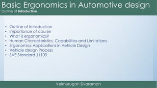
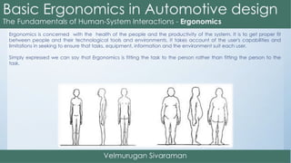
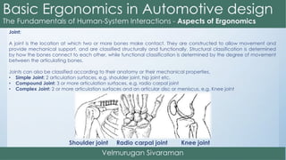
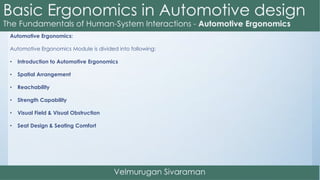
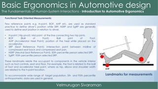
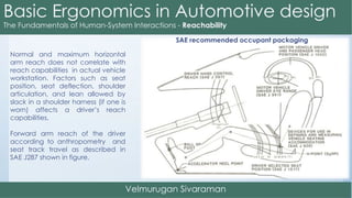
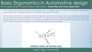
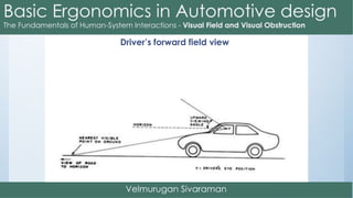
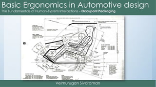

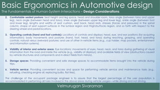
![SAE standard 941 has defined four eyellipsoids by combinations of two percentile values (95th and 99th)
and two seat track lengths (shorter than 133 mm and greater than 133 mm).
The eyellipsoids are defined by the lengths of their three axes (X, Y, and Z directions; shown in Figure
3.18 as EX, EY, and EZ). The values of EX, EY, and EZ for the 95th percentile eyellipse with TL23 > 133 mm are 206.4,
60.3, and 93.4 mm, respectively. (The values of EX, EY, and EZ for other combinations for percentile and seat track
travel are available in SAE standard J941.)
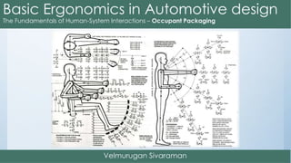
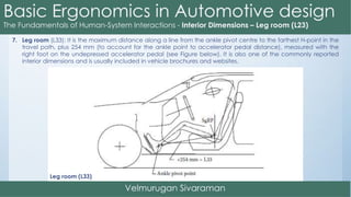
The eyellipses are located by specifying X, Y, and Z coordinates of their centroids. The ellipsoids are also
tilted downward in the forward direction by β = 12 degrees (i.e., the horizontal axes of the ellipsoids are rotated
counter clockwise by 12 degrees; see Figure in previous slide).
The coordinates of the left and right eyellipse centroids [(Xc, Ycl, Zc) and (Xc, Ycr, Zc), respectively] with
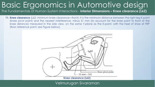
respect to the body zero are defined in SAE standard J941 as follows (see Figure in previous slide):
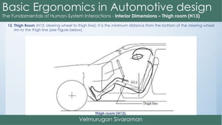
Xc = L1 + 664 + 0.587 (L6) − 0.178(H30) − 12.5t.
Ycl = W20 − 32.5 Ycr = W20 + 32.5 Zc = 638 + H30 + H8
where (L1, W1, H1) = coordinates of the PRP, L6 = horizontal distance between the BOF (or PRP) and the steering
wheel centre, and t = 0 for vehicle equipped with automatic transmission and t = 1 for vehicle with clutch pedal
(manual transmission). [Note: The SgRP coordinates with respect to the body zero are (L31, W20, H8 + H30). See
Figure 3.18. L1 = L31 − X95.]](https://image.slidesharecdn.com/basicergonomicsinautomotivedesign-160105161245/85/Basic-ergonomics-in-automotive-design-86-320.jpg)
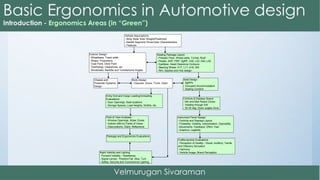
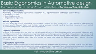
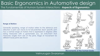
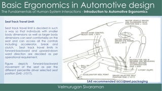
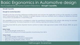
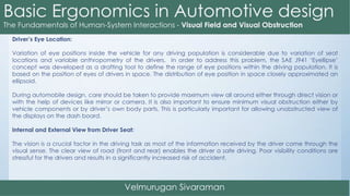
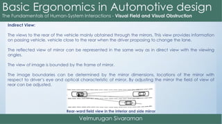
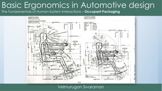
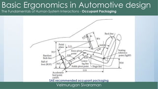
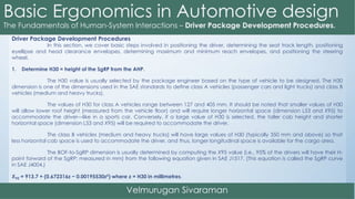
![Seatback angle:
The seatback angle (called A40 in SAE J1100) in automotive seating is defined by the angle of the torso line (back
line) of the SAE H-point machine or the two-dimensional (manikin) template (refer to SAE standards J826 and J4002
[SAE 2009]) with respect to the vertical. The seatback angle (seat recline angle) should allow drivers to assume their
preferred back angles. For passenger cars, drivers generally prefer to set the seatback angle between about 20°
and 26°. In trucks, due to the higher seat height (H30), drivers prefer to sit more erect with seatback angles between
about 12° and 18°.
Seatback height:
From an anthropometric accommodation viewpoint, the maximum seatback height can be selected as the fifth
percentile female acromial height, which is about 509 mm above the seat surface. However, considering the
Federal Motor Vehicle Safety requirements on head restraints, the seatback height is dictated by the headrest
design.
Lumbar area:
The seat contour in the lumbar area affects the shape of the seated person’s spinal column. The most important
characteristic of the seat contour in the lumbar region is that it should maintain the natural curvature (bulging
forward, i.e., convex, called lordosis) of the spinal column in the lower back region of the seated person. An
adjustable lumbar support that allows setting its height (i.e., up and down adjustment) and protrusion location (i.e.,
fore–aft adjustment) would allow accommodation of different individuals while maintaining their natural lordosis.](https://image.slidesharecdn.com/basicergonomicsinautomotivedesign-160105161245/85/Basic-ergonomics-in-automotive-design-90-320.jpg)

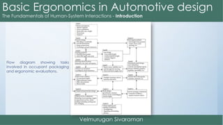
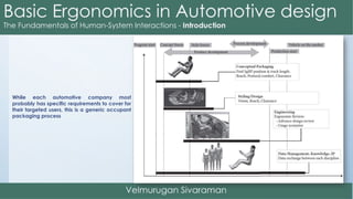
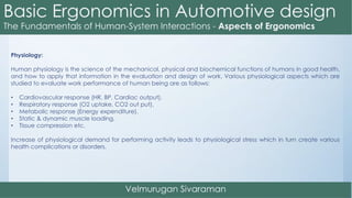
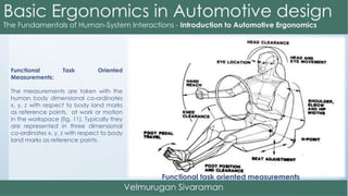
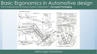
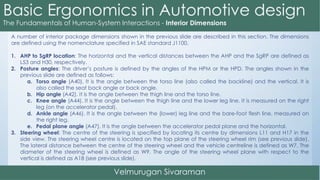
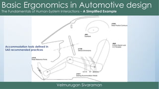
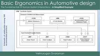
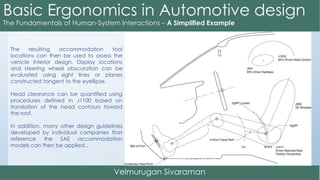
The document outlines the process and considerations for vehicle occupant packaging and ergonomic evaluations. It begins with establishing assumptions about the vehicle type and intended users. Exterior dimensions, seating position, controls layout, and visibility are then evaluated in detail. Tests are conducted to evaluate entry/exit, comfort, reach, visibility and more. The goal is to apply ergonomic principles to optimize the design for human use and performance.


![DESIGN AND FABRICATION OF THE IBM 90-90 SEAT BELT CLAMP KIA VEHICLE[1].pptx 2...](https://cdn.slidesharecdn.com/ss_thumbnails/designandfabricationoftheibm90-90seatbeltclampkiavehicle1-260116160442-70ff67fc-thumbnail.jpg?width=640&height=640&fit=bounds)


