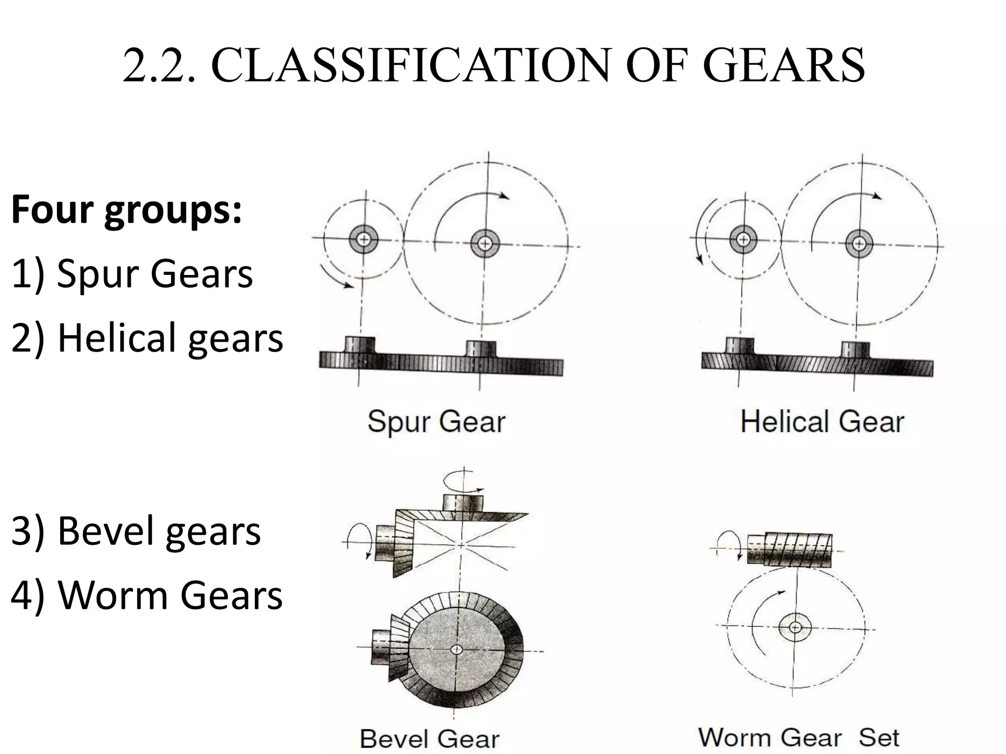
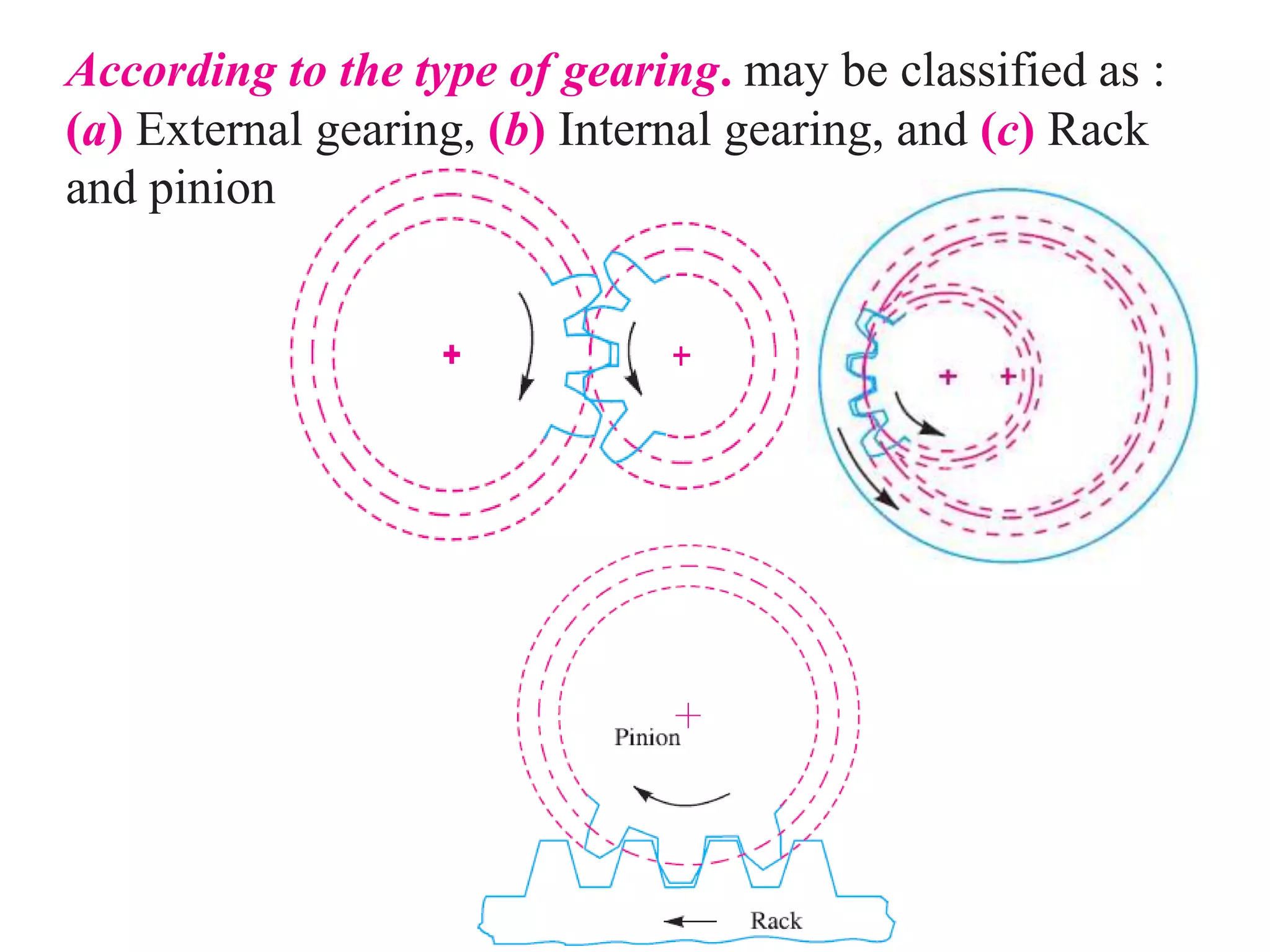
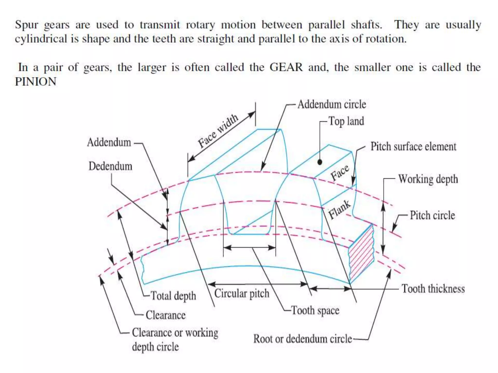
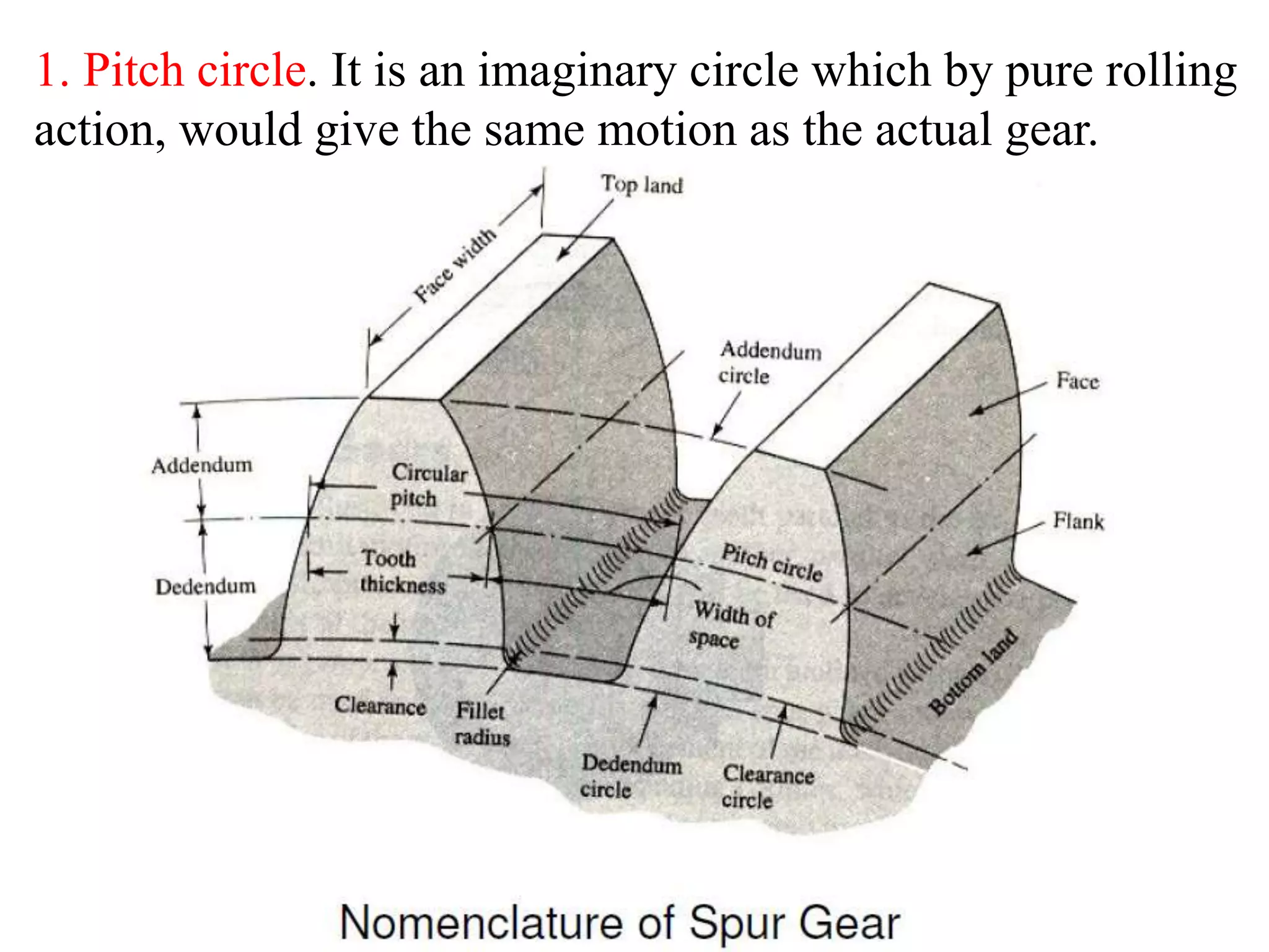
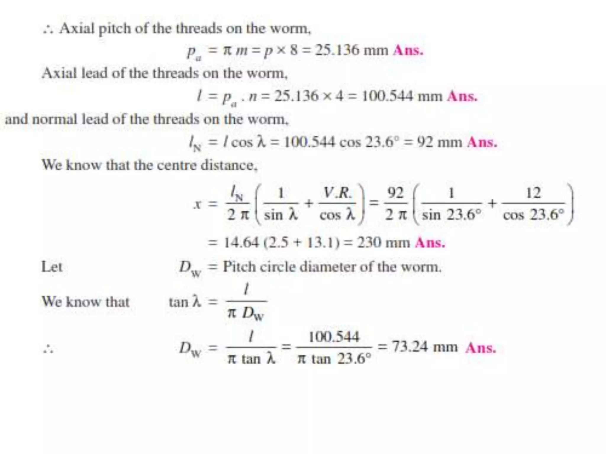
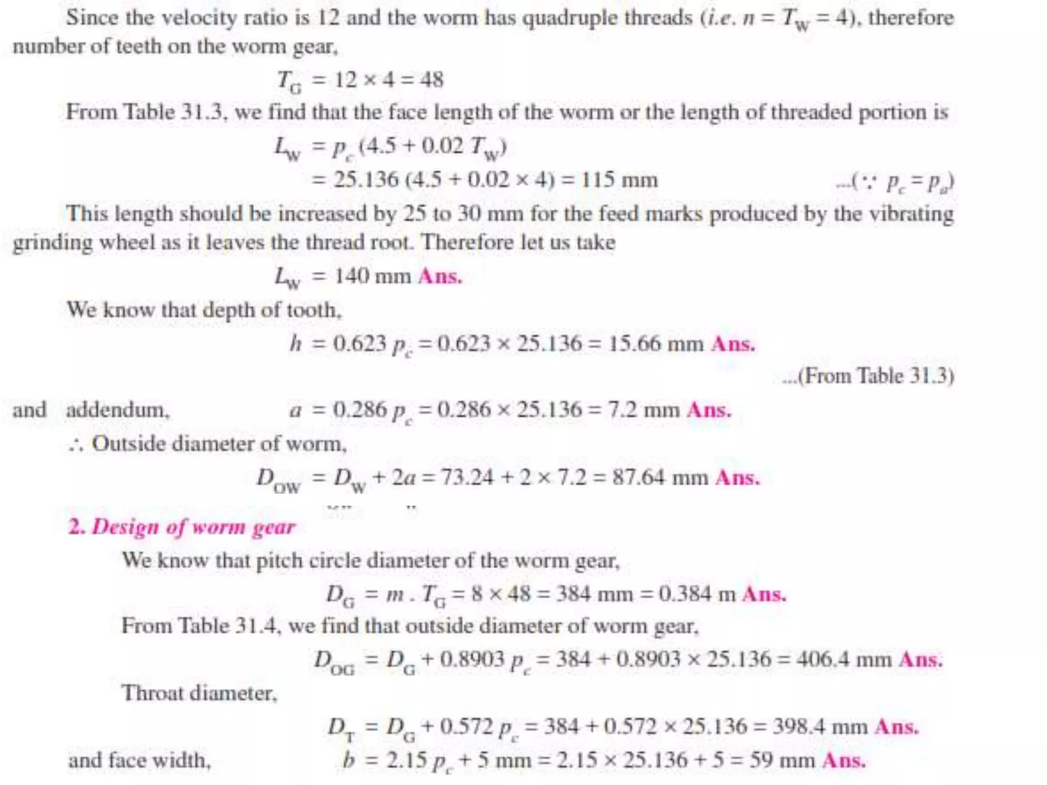
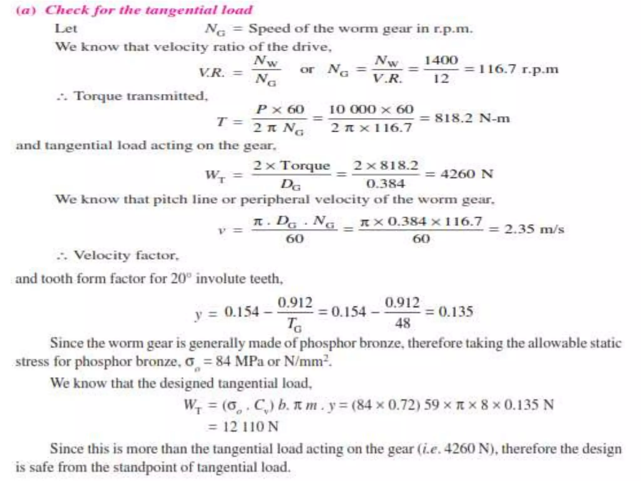
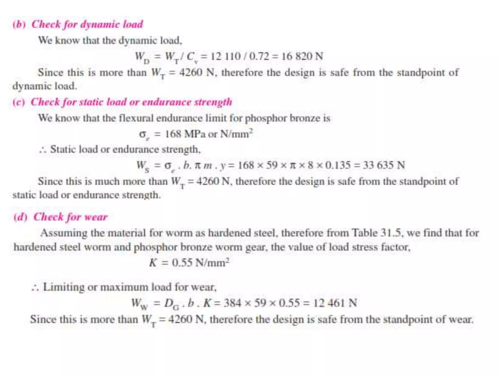
Kinematic synthesis deals with determining link lengths and orientations of mechanisms to satisfy motion requirements. This document discusses several key concepts in kinematic synthesis of planar mechanisms, including:
1) Movability/mobility synthesis which determines the degrees of freedom using Gruebler's criterion. The simplest mechanism is the four-bar linkage.
2) Transmission angle synthesis which aims to position links for maximum torque transmission, usually near 90°.
3) Limit positions and dead centers which are configurations of four-bar mechanisms where links are collinear.
4) Graphical synthesis methods using the pole and relative pole to determine link lengths and positions based on input/output motion specifications.
This document discusses bevel gears, including definitions of key terms, classifications, determination of pitch angle, proportions, strength calculations, and shaft design. It defines bevel gears as connecting two intersecting shafts at an angle to transmit power at a constant velocity ratio. Key points covered include:
- Bevel gears are classified as mitre, angular, crown, or internal depending on shaft intersection angle and pitch angle.
- Pitch angle is determined based on the shaft intersection angle and required velocity ratio.
- Strength is calculated using a modified Lewis equation accounting for bevel gear geometry.
- Forces on gears include tangential, radial, and axial components that create bearing reactions and thrust.
- Shaft design involves
- Today's lecture covers transmission angle, instantaneous center method, and locating instantaneous centers in mechanisms.
- The transmission angle between the output link and coupler is maximum at 90 degrees for maximum torque transmission.
- The instantaneous center method and relative velocity method can be used for velocity or acceleration analysis of mechanisms.
- The instantaneous center method uses the centers of rotation between two links to determine velocities. The number of instantaneous centers equals the number of possible link combinations.
This document provides a numerical problem on drawing a cam profile given various parameters of the cam and follower motion. It involves the following steps:
1) Constructing a displacement diagram showing the lift of the follower over the angular rotation of the cam for the outstroke, dwell and return stroke periods.
2) Dividing the outstroke and return stroke into equal parts on the displacement diagram and prime circle.
3) Drawing the base circle, offset circle and prime circle for the cam.
4) Transferring the displacement values from each part on the displacement diagram to the prime circle to obtain the cam profile curve.
Shaft & keys (machine design & industrial drafting )Digvijaysinh Gohil
This document discusses different types of shafts, keys, and their design considerations. It contains the following key points:
1. Shafts can be classified based on their shape (solid or hollow), application (transmitting, machine, spindle), and construction (rigid or flexible).
2. Keys are used to connect rotating machine elements to shafts and prevent relative motion. Common types include rectangular, square, parallel, gib-head, feather, and woodruff keys.
3. Shaft design considers factors like bending moment, shear stress, and material properties. Hollow shafts have higher strength-to-weight ratio than solid shafts of the same size.
This document contains 4 problems related to the design of mechanical springs. Problem 1 asks the reader to calculate the axial load and deflection per turn for a helical spring with given dimensions and material properties. Problem 2 involves designing a spring for a balance that can measure loads from 0-1000N over 80mm and fits inside a 25mm casing. Problem 3 asks the reader to design a compression spring for 1000N load over 25mm deflection using a spring index of 5. Problem 4 asks the reader to design a close-coiled helical compression spring that can handle loads from 2250-2750N over 6mm deflection with a spring index of 5.
This document discusses riveted joints, which are used to join metal plates. It describes the different types of rivet heads, riveted joint configurations like lap joints and butt joints, and how rivets are installed through heating and hammering. The document also discusses factors that determine the strength of riveted joints like the tearing resistance of plates, shearing resistance of rivets, and crushing resistance of plates and rivets. It explains how riveted joints can fail through tearing of plates, shearing of rivets, or crushing of plates/rivets. The efficiency of riveted joints is defined as the ratio of the joint's strength to the strength of an unriveted solid
1) The document discusses the design of shafts subjected to different loading conditions including bending, torsion, combined bending and torsion, fluctuating loads, and axial loads.
2) Formulas are provided to calculate the equivalent bending moment and equivalent twisting moment for shafts under various loading conditions.
3) Examples are presented to demonstrate how to use the formulas and determine the necessary shaft diameter based on allowable stresses.
This document lists 14 formulae related to spur gear design parameters. The key parameters include:
1) Angular velocity and speed ratio calculations based on number of teeth and RPM.
2) Calculation of circular pitch, module, and pitch circle radius based on diameter and number of teeth.
3) Addendum, dedendum, and path of contact dimensions.
4) Calculations for maximum path of approach and recess, and sliding velocities during engagement based on angular velocities.
5) Minimum number of teeth required to avoid interference based on gear dimensions.
6 shaft shafts subjected to fluctuating loadsDr.R. SELVAM
Shafts are often subjected to fluctuating loads in practice rather than constant loads. To design shafts like line shafts and counter shafts that experience fluctuating torque and bending moments, combined shock and fatigue factors must be accounted for in calculating the twisting moment and bending moment. These equivalent moments are calculated using combined shock and fatigue factors for bending (Km) and torsion (Kt), with recommended values for Km and Kt provided in a table.
This document contains numerical problems and solutions related to kinematics of spur gears. It includes 5 problems covering topics like calculating addendum, path of contact, arc of contact, contact ratio, angle turned by pinion, and velocity of sliding at different points for different gear configurations. The problems have varying gear parameters like number of teeth, pressure angle, module, pitch circle radius, angular velocity etc. Detailed step-by-step solutions are shown for each problem.
This document discusses different types of keys used to connect a shaft to a pulley or gear. It describes sunk keys like rectangular, square, parallel, gib-head, feather, and woodruff keys. It also covers saddle keys, tangent keys, round keys, and splined shafts. The key transmits torque from the shaft and can fail due to shearing or crushing stresses. For a key to be equally strong against both types of stresses, it should have a square cross-section where the width and thickness are equal.
An academic presentation that highlights main shafts applications and conduct stress and fatigue analysis in shafts as shafts being an essential part in the automotive manufacturing
The document discusses measurement and metrology of screw threads. It begins with definitions of screw thread terminology such as major diameter, minor diameter, pitch, angle, and forms of threads. It then describes methods for measuring the major diameter, minor diameter, effective diameter, and pitch of screw threads. The key measurement methods discussed are using micrometers, pitch gauges, and a tool maker's microscope. The goal is to understand principles and techniques for measuring characteristics of screw threads.
This presentation summarizes cams with specified contours and provides examples of tangent cams with reciprocating roller followers. It was submitted by three mechanical engineering students at Gandhinagar Institute of Technology.
The document defines cams and followers as a higher pair that can provide reciprocating or oscillating motion. It then discusses cams with specified contours where the cam profile is defined to produce a desired follower motion profile.
As an example, it examines tangent cams where the flanks are straight and tangential to the base and nose circles. Expressions are derived for the displacement, velocity, and acceleration of the follower roller in two cases: when in contact with the straight flanks and when in contact with the nose circle
The document contains 38 questions related to machine design. The questions cover topics such as standardization of sizes, tolerances, fits, design of joints, shafts, levers, frames and other machine elements. Design calculations are required to determine dimensions that satisfy given loading and stress criteria. Materials, their properties and appropriate factors of safety are provided. References for solutions and examples are given from standard machine design textbooks.
This document defines key terminology used in gear calculations, including:
- Pitch circle - An imaginary circle used to define gear size and motion
- Pitch diameter - The diameter of the pitch circle
- Addendum - The radial distance from the pitch circle to the top of the tooth
- Dedendum - The radial distance from the pitch circle to the bottom of the tooth
- Clearance - The radial distance between the top of one tooth and bottom of the other in mesh
This document discusses spur gears and how they transmit motion and power. It explains that spur gears have teeth cut into the periphery of circular wheels that mesh together to transfer rotation between two shafts without slipping. The motion ratio is determined by the relative sizes of the gears' pitch circles. Involute tooth profiles are commonly used as they allow some variability in center distance without changing the speed ratio. Cycloidal teeth are also discussed but are less commonly used.
The document describes the design of a cotter joint to withstand a maximum tensile load of 6KN. It provides definitions of the variables involved in the joint design. It then outlines 10 steps to size the different parts of the joint based on the material properties and load value, determining values for the diameters, thicknesses, and distances. The final section provides the results of the full design process.
Position analysis and dimensional synthesisPreetshah1212
This document provides an overview of position analysis and dimensional synthesis for kinematics of machines. It discusses topics such as position and displacement, dimensional synthesis, function generation, path generation, motion generation, limiting conditions like toggle positions and transmission angles, and both graphical and algebraic methods for position analysis including vector loops and the use of complex numbers. The key steps of graphical position analysis and the algebraic algorithm using Freudenstein's equation are described.
The document discusses the design of various types of rigid and flexible couplings. It provides steps to design a flange coupling connecting two shafts transmitting 37.5 kW power at 180 rpm. Key details include calculating torque from power, selecting shaft diameter, coupling dimensions based on standards, and checking design of key and bolts for shearing and crushing. The document also provides problems and solutions for designing flange, muff, and clamp couplings for given power and speed conditions.
This presentation contains basic idea regarding spur gear and provides the best equations for designing of spur gear. One can Easily understand all the parameters required to design a Spur Gear
The worm gears are widely used for transmitting power at high velocity ratios between non-intersecting shafts that are generally, but not necessarily, at right angles.
It can give velocity ratios as high as 300 : 1 or more in a single step in a minimum of space, but it has a lower efficiency.
This document discusses different types of gear trains including simple, compound, reverted, and epicyclic gear trains. It provides details on the components, configurations, terminology, and methods for calculating speed and velocity ratios for each type of gear train. Key points covered include how simple gear trains involve one gear on each shaft, compound gear trains have multiple gears on a shaft, reverted gear trains have coaxial input and output shafts, and epicyclic gear trains allow shaft axes to move relative to a fixed axis. Formulas and a tabular method are presented for analyzing epicyclic gear trains.
Unit 5 Design of Threaded and Welded JointsMahesh Shinde
1) The document discusses different types of threaded and welded joints. It describes various threaded fasteners like bolts, studs, screws and their characteristics.
2) For threaded joints subjected to eccentric loads, it explains how to calculate the primary and secondary shear forces on each bolt. This involves finding the center of gravity of the bolt system and determining the forces based on the load direction.
3) Sample problems are included to demonstrate how to select the bolt size based on the maximum resultant shear force and required factor of safety. Calculations are shown for eccentrically loaded bolted joints with the load in the plane of bolts.
1. The document provides an introduction to different types of gears including spur gears, helical gears, and bevel gears. It discusses key terms used in gears such as pitch circle, pressure angle, addendum, and defines formulas for calculating values like circular pitch and diametral pitch.
2. Design considerations for gear drives are outlined, including power transmitted, speeds, velocity ratio and center distance. Strength calculations using the Lewis equation and factors for dynamic loading and wear are also covered.
3. The summary provides an overview of the main topics and concepts discussed in the gear document.
Power transmission involves moving energy from where it is generated to where it is applied. Power is defined as units of energy per unit time. Gears are used to transmit power between rotating or linear shafts by means of teeth that progressively engage. There are different types of gears that transmit motion between parallel shafts, intersecting shafts, and non-parallel shafts. Gear drives are commonly used for power transmission due to their ability to transmit high power and torque over a wide range of speed ratios in a compact package.
The document provides information about different types of gears including spur gears, helical gears, bevel gears, worm gears, and rack and pinion gears. It discusses key gear terminology such as pitch circle, pitch diameter, pressure angle, addendum, dedendum, diametral pitch, and module. The document also covers gear tooth profiles including cycloidal and involute profiles and the law of gearing for constant velocity ratio. Examples of gear calculations for addendum, path of contact, arc of contact, and contact ratio are presented.
This document discusses gear transmissions. It begins by explaining that slippage commonly occurs in belt or chain drives, reducing the speed ratio between two shafts. Precise machines like clocks require a definitive speed ratio, which can only be achieved with gears. Gears are also needed when the distance between the drive and driven components is very small. The document then discusses various types of gears, classified by position of shafts, surface speed, drive method, and tooth placement. It provides terminology used in gears like pitch circle, pitch point, pressure angle, and explains involute and cycloidal tooth profiles that satisfy the constant velocity ratio condition.
This document discusses different types of gears and their components. It begins by defining gears and their purpose in power transmission systems. There are three main types of gears defined by their shaft positions: parallel, intersecting, and non-parallel/non-intersecting. Spur gears have parallel shafts while bevel gears have intersecting shafts. Worm gears are non-parallel and non-intersecting. The document then discusses specific gears like spur gears, helical gears, rack and pinion gears, and bevel gears. It also covers gear tooth profiles, terminology, interference issues, and measurement techniques.
Helical and spur gears are types of gears that can be used to transmit torque between parallel shafts. Spur gears have straight teeth parallel to the shaft axis, while helical gears have teeth wrapped in a helix around the gear. Helical gears provide a smoother drive than spur gears due to their gradual engagement of teeth. Key terminology for gears includes pitch circle, pitch diameter, addendum, dedendum, diametral pitch, and module. Gears can be classified based on shaft positioning, peripheral velocity, and type of gearing such as external, internal, rack and pinion.
This document discusses spur gear machine design and is submitted by a group of students. It covers topics such as the definition of spur gears, classifications of gears according to axis position and peripheral velocity, advantages and disadvantages of gears, terms used in gears including pitch circle and pressure angle, and the law of gearing which states that the common normal at the point of contact between gear teeth must pass through the pitch point. References for further information are also provided.
Machine Elements and Design- Lecture 8.pptxJeromeValeska5
Gears transmit power and motion between two shafts. There are different types of gears classified based on the orientation of shafts and teeth. Gear geometry includes parameters like pitch circle, pressure angle, addendum and dedendum. Strength of gear teeth depends on factors like load, tooth dimensions and material properties. Dynamic loads account for inaccuracies and are higher than steady loads. Design considers factors like load calculation, permissible stresses, and load distribution to ensure safe and reliable operation of gear drives.
spur gear.pptx, type of gear and design of gearhaymanot16
Gears are used to transmit power between two shafts and can precisely control velocity ratios. Belts and chains are used for larger center distances while gears are used for smaller distances. Gears work by the progressive engagement of teeth and precisely mesh the teeth profiles to maintain a constant velocity ratio between the driving and driven shafts. Gears offer advantages like compact size, positive drives, wide speed ratios and ability to transmit power over varying shaft configurations but require precise alignment and lubrication.
1. Gears are used to transmit motion between two shafts where slipping needs to be avoided. Gears have teeth cut along the periphery that mesh to ensure positive drive.
2. Gears can be classified based on the position and orientation of shaft axes, peripheral velocity, type of gearing, and position of teeth on the gear surface. Common types include spur gears, helical gears, bevel gears, and rack and pinion.
3. Involute teeth profiles are commonly used as they satisfy the law of gearing to ensure constant velocity ratio between meshing gears for all positions.
The document discusses gears and their classification. It defines various gear types including spur gears, helical gears, bevel gears, worm gears, and rack gears. It covers gear terminology such as pressure angle and describes how parameters like pressure angle and center distance affect gear performance and interference. Methods to avoid interference include increasing center distance, tooth modification, and changing the number of teeth. Backlash is also defined as the clearance between mating gear teeth.
Bevel gears are used to transmit motion between two intersecting shafts. They can have straight or spiral teeth and are usually used at a 90 degree shaft angle but can be made for any angle. Bevel gear design considers the clearance, total depth, working depth, tooth thickness, and tooth space. Common types include straight, spiral, zerol, and hypoid gears which are used in differentials, drills, and other applications requiring power transfer between non-parallel shafts. Material selection depends on operating conditions and environment.
This document discusses spur gear terminology and calculations. It defines key gear terms like addendum, dedendum, pitch diameter, root diameter, and pressure angle. It also explains that the most common pressure angles for spur gears are 141/2, 20, and 25 degrees, with 141/2 degrees becoming obsolete. The larger pressure angles allow for stronger teeth and fewer teeth per gear. Any two meshing gears must have the same pressure angle. The document also discusses couplings, which connect two shafts to transmit power while allowing for some misalignment or movement and reducing shock between the shafts.
Three new models for evaluation of standard involute spur gear | Mesh Analysis AliRaza1767
This document proposes three new models for evaluating the mesh stiffness of spur gears. Model 1 considers gear bodies and teeth to be elastic and calculates mesh forces and tooth deflections at different positions. Model 2 considers teeth to be elastic and gear bodies to be rigid. It applies torque to the gear and measures angular displacement. Model 3 uses corner deflection values at arbitrary angles between teeth. Finite element analysis is used to validate the models.
Gears are used to transmit power between two shafts. Spur gears have parallel teeth and are used to connect parallel shafts. Helical gears have teeth inclined to the axis which increases load capacity and reduces noise compared to spur gears. Bevel gears are used for intersecting shafts with teeth formed along truncated cones. Worm gears consist of a worm and wheel used to connect non-parallel, non-intersecting shafts and can provide high speed ratios up to 300:1. Different gear materials, manufacturing methods, and potential failure modes are discussed.
Gears are used to transmit motion between parallel or non-parallel shafts. The document discusses different types of gears including spur gears, helical gears, bevel gears, and worm gears. It describes gear terminology such as pitch circle, diametral pitch, pressure angle, and contact ratio. Cycloidal and involute tooth profiles are examined, with involute gears being more commonly used. Interference, gear trains, and automotive transmissions are also summarized.
DEEP LEARNING FOR SMART GRID INTRUSION DETECTION: A HYBRID CNN-LSTM-BASED MODELgerogepatton
As digital technology becomes more deeply embedded in power systems, protecting the communication
networks of Smart Grids (SG) has emerged as a critical concern. Distributed Network Protocol 3 (DNP3)
represents a multi-tiered application layer protocol extensively utilized in Supervisory Control and Data
Acquisition (SCADA)-based smart grids to facilitate real-time data gathering and control functionalities.
Robust Intrusion Detection Systems (IDS) are necessary for early threat detection and mitigation because
of the interconnection of these networks, which makes them vulnerable to a variety of cyberattacks. To
solve this issue, this paper develops a hybrid Deep Learning (DL) model specifically designed for intrusion
detection in smart grids. The proposed approach is a combination of the Convolutional Neural Network
(CNN) and the Long-Short-Term Memory algorithms (LSTM). We employed a recent intrusion detection
dataset (DNP3), which focuses on unauthorized commands and Denial of Service (DoS) cyberattacks, to
train and test our model. The results of our experiments show that our CNN-LSTM method is much better
at finding smart grid intrusions than other deep learning algorithms used for classification. In addition,
our proposed approach improves accuracy, precision, recall, and F1 score, achieving a high detection
accuracy rate of 99.50%.
Embedded machine learning-based road conditions and driving behavior monitoringIJECEIAES
Car accident rates have increased in recent years, resulting in losses in human lives, properties, and other financial costs. An embedded machine learning-based system is developed to address this critical issue. The system can monitor road conditions, detect driving patterns, and identify aggressive driving behaviors. The system is based on neural networks trained on a comprehensive dataset of driving events, driving styles, and road conditions. The system effectively detects potential risks and helps mitigate the frequency and impact of accidents. The primary goal is to ensure the safety of drivers and vehicles. Collecting data involved gathering information on three key road events: normal street and normal drive, speed bumps, circular yellow speed bumps, and three aggressive driving actions: sudden start, sudden stop, and sudden entry. The gathered data is processed and analyzed using a machine learning system designed for limited power and memory devices. The developed system resulted in 91.9% accuracy, 93.6% precision, and 92% recall. The achieved inference time on an Arduino Nano 33 BLE Sense with a 32-bit CPU running at 64 MHz is 34 ms and requires 2.6 kB peak RAM and 139.9 kB program flash memory, making it suitable for resource-constrained embedded systems.
ACEP Magazine edition 4th launched on 05.06.2024Rahul
This document provides information about the third edition of the magazine "Sthapatya" published by the Association of Civil Engineers (Practicing) Aurangabad. It includes messages from current and past presidents of ACEP, memories and photos from past ACEP events, information on life time achievement awards given by ACEP, and a technical article on concrete maintenance, repairs and strengthening. The document highlights activities of ACEP and provides a technical educational article for members.
Using recycled concrete aggregates (RCA) for pavements is crucial to achieving sustainability. Implementing RCA for new pavement can minimize carbon footprint, conserve natural resources, reduce harmful emissions, and lower life cycle costs. Compared to natural aggregate (NA), RCA pavement has fewer comprehensive studies and sustainability assessments.
Harnessing WebAssembly for Real-time Stateless Streaming PipelinesChristina Lin
Traditionally, dealing with real-time data pipelines has involved significant overhead, even for straightforward tasks like data transformation or masking. However, in this talk, we’ll venture into the dynamic realm of WebAssembly (WASM) and discover how it can revolutionize the creation of stateless streaming pipelines within a Kafka (Redpanda) broker. These pipelines are adept at managing low-latency, high-data-volume scenarios.
Presentation of IEEE Slovenia CIS (Computational Intelligence Society) Chapte...University of Maribor
Slides from talk presenting:
Aleš Zamuda: Presentation of IEEE Slovenia CIS (Computational Intelligence Society) Chapter and Networking.
Presentation at IcETRAN 2024 session:
"Inter-Society Networking Panel GRSS/MTT-S/CIS
Panel Session: Promoting Connection and Cooperation"
IEEE Slovenia GRSS
IEEE Serbia and Montenegro MTT-S
IEEE Slovenia CIS
11TH INTERNATIONAL CONFERENCE ON ELECTRICAL, ELECTRONIC AND COMPUTING ENGINEERING
3-6 June 2024, Niš, Serbia
Introduction- e - waste – definition - sources of e-waste– hazardous substances in e-waste - effects of e-waste on environment and human health- need for e-waste management– e-waste handling rules - waste minimization techniques for managing e-waste – recycling of e-waste - disposal treatment methods of e- waste – mechanism of extraction of precious metal from leaching solution-global Scenario of E-waste – E-waste in India- case studies.
A review on techniques and modelling methodologies used for checking electrom...nooriasukmaningtyas
The proper function of the integrated circuit (IC) in an inhibiting electromagnetic environment has always been a serious concern throughout the decades of revolution in the world of electronics, from disjunct devices to today’s integrated circuit technology, where billions of transistors are combined on a single chip. The automotive industry and smart vehicles in particular, are confronting design issues such as being prone to electromagnetic interference (EMI). Electronic control devices calculate incorrect outputs because of EMI and sensors give misleading values which can prove fatal in case of automotives. In this paper, the authors have non exhaustively tried to review research work concerned with the investigation of EMI in ICs and prediction of this EMI using various modelling methodologies and measurement setups.
2. 2.1. Introduction
1.Gears are defined as toothed wheels, which transmit
power and motion from one shaft to another by means
of successive engagement of teeth. The center distance
between the shafts is relatively small.
2. It can transmit very large power.
3. It is a positive, and the velocity ratio remains
constant.
4. It can transmit motion at a very low velocity.
3. 2.2. CLASSIFICATION OF GEARS
Four groups:
1) Spur Gears
2) Helical gears
3) Bevel gears
4) Worm Gears
4. According to the type of gearing. may be classified as :
(a) External gearing, (b) Internal gearing, and (c) Rack
and pinion.
5.
6. 1. Pitch circle. It is an imaginary circle which by pure rolling
action, would give the same motion as the actual gear.
7. 2. Pitch circle diameter. It is the diameter of the pitch
circle. The size of the gear is usually specified by the pitch
circle diameter. It is also called as pitch diameter.
3. Pitch point. It is a common point of contact between two
pitch circles.
4. Pitch surface. It is the surface of the rolling discs which
the meshing gears have replaced at the pitch circle.
5. Pressure angle or angle of obliquity. It is the angle
between the common normal to two gear teeth at the point
of contact and the common tangent at the pitch point.
8. It is usually denoted by φ. The standard pressure angles are 14 /2° and
20°.
6. Addendum. It is the radial distance of a tooth from the pitch circle to
the top of the tooth.
7. Dedendum. It is the radial distance of a tooth from the pitch circle to
the bottom of the tooth.
8. Addendum circle. It is the circle drawn through the top of the teeth
and is concentric with the pitch circle.
9. Dedendum circle. It is the circle drawn through the bottom of the
teeth. It is also called root circle.
Note : Root circle diameter = Pitch circle diameter × cos φ, where φ is
the pressure angle.
9. 10. Circular pitch. It is the distance measured on the
circumference of the pitch circle from a point of one tooth
to the corresponding point on the next tooth. It is usually
denoted by .
Mathematically,
Circular pitch = π D/T
Where
D = Diameter of the pitch circle, and
T = Number of teeth on the wheel.
10. A little consideration will show that the two gears will
mesh together correctly, if the two wheels have the same
circular pitch.
Note : If D1 and D2 are the diameters of the two meshing
gears having the teeth T1 and T2 respectively; then for
them to mesh correctly,
11. 11. Diametral pitch. It is the ratio of number of teeth to the
pitch circle diameter in millimeters. It denoted by pd.
Mathematically,
where T = Number of teeth, and
D = Pitch circle diameter
12. 12. Module. It is the ratio of the pitch circle diameter in
millimeters to the number of teeth. It is usually denoted by m.
Mathematically, Module, m = D / T
Note : The recommended series of modules in Indian
Standard are 1, 1.25, 1.5, 2, 2.5, 3, 4, 5, 6, 8, 10, 12, 16,
20, 25, 32, 40 and 50.
The modules 1.125, 1.375, 1.75, 2.25, 2.75, 3.5, 4.5,5.5, 7, 9,
11, 14, 18, 22, 28, 36 and 45 are of second choice.
13. 13. Clearance. It is the radial distance from the top of the
tooth to the bottom of the tooth, in a meshing gear. A circle
passing through the top of the meshing gear is known as
clearance circle.
14. Total depth. It is the radial distance between the
addendum and the dedendum circle of a gear. It is equal to
the sum of the addendum and dedendum.
15. Working depth. It is radial distance from the addendum
circle to the clearance circle. It is equal to the sum of the
addendum of the two meshing gears.
14. 16. Tooth thickness. It is the width of the tooth measured
along the pitch circle.
17. Tooth space. It is the width of space between the two
adjacent teeth measured along the pitch circle.
18. Backlash. It is the difference between the tooth space
and the tooth thickness, as measured
on the pitch circle.
15. 19. Face of the tooth. It is surface of the tooth above the
pitch surface.
20. Top land. It is the surface of the top of the tooth.
21. Flank of the tooth. It is the surface of the tooth below
the pitch surface.
22. Face width. It is the width of the gear tooth measured
parallel to its axis.
23. Profile. It is the curve formed by the face and flank of
the tooth.
16. 24. Fillet radius. It is the radius that connects the root
circle to the profile of the tooth.
25. Path of contact. It is the path traced by the point of
contact of two teeth from the beginning to the end of
engagement.
26. Length of the path of contact. It is the length of the
common normal cut-off by the addendum circles of the
wheel and pinion.
17. 27. Arc of contact. It is the path traced by a point on the pitch
circle from the beginning to the end of engagement of a given
pair of teeth. The arc of contact consists of two parts, i.e.
(a) Arc of approach. It is the portion of the path of contact
from the beginning of the engagement to the pitch point.
(b) Arc of recess. It is the portion of the path of contact from
the pitch point to the end of the engagement of a pair of teeth.
Note : The ratio of the length of arc of contact to the circular
pitch is known as contact ratio i.e. number of pairs of teeth in
contact.
18. Law of Gearing
“The common normal at the point of contact between a
pair of teeth must always pass through the pitch point”
This is fundamental condition which must be satisfied
while designing the profiles for the teeth of gear wheels.
If D1 and D2 are pitch circle diameters of wheel 1 and 2
having teeth T1 and T2 respectively, then velocity ratio,
19. 2.3. Forms of Teeth
In actual practice, following are the two types of teeth
commonly used.
1. Cycloidal teeth ; and 2. Involute teeth.
A cycloid is the curve traced by a point on the
circumference of a circle which rolls without slipping on a
fixed straight line.
Fig - Construction of cycloidal teeth of a gear.
20. An involute of a circle is a plane curve generated by
a point on a tangent, which rolls on the circle
without slipping.
Fig _ Construction of involute teeth.
21. 2.3.1 Comparison Between Involute and Cycloidal
Gears
In actual practice, the involute gears are more commonly
used as compared to cycloidal gears, due to the following
advantages :
Following are the advantages of involute gears :
1. The most important advantage of the involute gears is
that the center distance for a pair of involute gears can be
varied within limits without changing the velocity ratio.
This is not true for cycloidal gears which requires exact
center distance to be maintained.
22. 2. In involute gears, the pressure angle, from the start of the
engagement of teeth to the end of the engagement, remains constant. It
is necessary for smooth running and less wear of gears .But in
cycloidal gears, the pressure angle is maximum at the beginning of
engagement, reduces to zero at pitch point, starts increasing and again
becomes maximum at the end of engagement. This results in less
smooth running of gears. 3. The face and flank of involute teeth are
generated by a single curve whereas in cycloidal gears, double curves
(i.e. epicycloid and hypocycloid) are required for the face and flank
respectively.
23. Following are the advantages of cycloidal gears :
1. Since the cycloidal teeth have wider flanks, therefore
the cycloidal gears are stronger than the involute gears for
the same pitch. Due to this reason, the cycloidal teeth are
preferred specially for cast teeth.
2. In cycloidal gears, the contact takes place between a
convex flank and concave surface, whereas in involute
gears, the convex surfaces are in contact.
24. This condition results in less wear in cycloidal gears as
compared to involute gears. However the difference in
wear is negligible.
3. In cycloidal gears, the interference does not occur at all.
Though there are advantages of cycloidal gears but they are
outweighed by the greater simplicity and flexibility of the
involute gears.
25.
26. The tooth profile of the 14 1/2° full depth involute
system was developed for use with gear hobs for spur
and helical gears.
The tooth profile of the 20° full depth involute system
may be cut by hobs.
The increase of the pressure angle from 14 1/2° to 20°
results in a stronger tooth, because the tooth acting as a
beam is wider at the base. The 20° stub involute system
has a strong tooth to take heavy loads.
27. Table 2.1. Standard proportions of gear systems.
Table 2.2. Minimum number of teeth on the pinion in order to avoid interference.
28. 2.4 Gear Materials
The material used for the manufacture of gears depends
upon the strength and service conditions like wear, noise
The gears may be manufactured from metallic or non-
metallic materials.
The metallic gears with cut teeth are commercially
obtainable in cast iron, steel and bronze. The nonmetallic
materials like wood, rawhide, compressed paper and
synthetic resins like nylon are used for gears, especially
for reducing noise.
29. The cast iron is widely used for the manufacture of gears
due to its good wearing properties, excellent machinability
and ease of producing complicated shapes by casting
method. The cast iron gears with cut teeth may be
employed, where smooth action is not important.
The steel is used for high strength gears and steel may be
plain carbon steel or alloy steel. The steel gears are usually
heat treated in order to combine properly the toughness
and tooth hardness.
32. Design Considerations for a Gear Drive
In the design of a gear drive, the following data is usually given :
1. The power to be transmitted.
2. The speed of the driving gear,
3. The speed of the driven gear or the velocity ratio, and
4. The center distance.
The following requirements must be met in the design of a gear drive :
(a) The gear teeth should have sufficient strength so that they will not fail under static
loading or dynamic loading during normal running conditions.
(b) The gear teeth should have wear characteristics so that their life is satisfactory.
(c) The use of space and material should be economical.
(d) The alignment of the gears and deflections of the shafts must be considered
because they effect on the performance of the gears.
(e) The lubrication of the gears must be satisfactory.
33. The maximum value of the bending stress (or the permissible working stress),
at the critical section is given by:
Fig.Tooth of a gear
34. therefore in order to find the value of y, the quantities t, h and pc may be determined
analytically or measured from the drawing similar to Fig. above. It may be noted that
if the gear is enlarged, the distances t, h and pc will each increase proportionately.
Therefore the value of y will remain unchanged. A little consideration will show that
the value of y is independent of the size of the tooth and depends only on the number
of teeth on a gear and the system of teeth.
35. The value of y in terms of the number of teeth may be expressed
as follows :
40. Table 2.6 Values of maximum allowable tooth error in action (e) verses pitch
line velocity, for well cut commercial gears.
The maximum allowable tooth error in action (e) depends upon the pitch line
velocity (v) and the class of cut of the gears. The following tables show the values of
tooth errors in action (e) for the different values of pitch line velocities and modules.
45. Causes of Gear Tooth Failure
The different modes of failure of gear teeth and their possible remedies to avoid
the failure, are as follows :
1. Bending failure. Every gear tooth acts as a cantilever. If the total repetitive
dynamic load acting on the gear tooth is greater than the beam strength of the
gear tooth, then the gear tooth will fail in bending, i.e. the gear tooth will
break. In order to avoid such failure, the module and face width of the gear is
adjusted so that the beam strength is greater than the dynamic load.
2. Pitting. It is the surface fatigue failure which occurs due to many repetition of
Hertz contact stresses. The failure occurs when the surface contact stresses are
higher than the endurance limit of the material. In order to avoid the pitting, the
dynamic load between the gear tooth should be less than the wear strength of the
gear tooth.
3. Scoring. The excessive heat is generated when there is an excessive surface
pressure, high speed or supply of lubricant fails. It is a stick-slip phenomenon in
which alternate shearing and welding takes place rapidly at high spots. This type of
failure can be avoided by properly designing the parameters such as speed, pressure
and proper flow of the lubricant, so that the temperature at the rubbing faces is
within the permissible limits.
46. 4. Abrasive wear. The foreign particles in the lubricants such
as dirt, dust or burr enter between the tooth and damage the
form of tooth. This type of failure can be avoided by providing
filters for the lubricating oil or by using high viscosity
lubricant oil which enables the formation of thicker oil film
and hence permits easy passage of such particles without
damaging the gear surface.
5. Corrosive wear. The corrosion of the tooth surfaces is
mainly caused due to the presence of corrosive elements such
as additives present in the lubricating oils. In order to avoid
this type of wear, proper anti-corrosive additives should be
used.
50. Helical Gears
A helical gear has teeth in form of helix around the gear. Two
such gears may be used to connect two parallel shafts in place of
spur gears.
The helixes may be right handed on one gear and left handed on
the other. The pitch surfaces are cylindrical as in spur gearing, but
the teeth instead of being parallel to the axis, wind around the
cylinders helically like screw threads. The teeth of helical gears
with parallel axis have line contact, as in spur gearing. This
provides gradual engagement and continuous contact of the
engaging teeth. Hence helical gears give smooth drive with a high
efficiency of transmission.
59. Problem 1. A pair of helical gears are to transmit 15 kW. The teeth
are 20° stub in diametral plane and have a helix angle of 45°. The
pinion runs at 10 000 r.p.m. and has 80 mm pitch diameter. The gear
has 320 mm pitch diameter. If the gears are made of cast steel having
allowable static strength of 100 MPa; determine a suitable module
and face width from static strength considerations and check the
gears for wear, given σes = 618 MPa.
60.
61.
62.
63. Problem 2. Design a pair of helical gears for transmitting 22 kW. The speed of the
driver gear is 1800r.p.m. and that of driven gear is 600r.p.m. The helix angle is 30°
and profile is corresponding to 20° full depth system. The driver gear has 24 teeth.
Both the gears are made of cast steel with allowable static stress as 50MPa. Assume
the face width parallel to axis as 4 times the circular pitch and the overhang for each
gear as150mm. The allowable shear stress for the shaft material may be taken as
50MPa. The form factor may be taken as 0.154 – 0.912 / TE, where TE is the
equivalent number of teeth. The velocity factor may be taken as , 350 /(350 + v)
where v is pitch line velocity in m / min. The gears are required to be designed only
against bending failure of the teeth under dynamic condition.
64.
65.
66.
67. Bevel Gears
The bevel gears are used for transmitting power at a constant velocity
ratio between two shafts whose axes intersect at a certain angle. The pitch
surfaces for the bevel gear are frustums of cones.
68. Classification of Bevel Gears
1. Mitre gears. When equal bevel gears (having equal teeth and equal pitch angles)
connect two shafts whose axes intersect at right angle, as shown in Fig. (a), below.
2. Angular bevel gears. When the bevel gears connect two shafts whose axes intersect at
an angle other than a right angle, then they are known as angular bevel gears.
3. Crown bevel gears. When the bevel gears connect two shafts whose axes intersect at an
angle greater than a right angle and one of the bevel gears has a pitch angle of 90º.The
crown gear corresponds to a rack in spur gearing, as shown in Fig. (b).
4. Internal bevel gears. When the teeth on the bevel gear are cut on the inside of the pitch
cone. Note : The bevel gears may have straight or spiral teeth. It may be assumed, unless
otherwise stated, that the bevel gear has straight teeth and the axes of the shafts intersect at
right angle.
70. 5. Addendum angle. It is the angle subtended by the addendum of the tooth at the
cone center. It is denoted by ‘α’ Mathematically, addendum angle,
Where
6. Dedendum angle. It is the angle subtended by the dedendum of the tooth at the cone
center.It is denoted by ‘β’. Mathematically, dedendum angle,
Where
7. Face angle. It is the angle subtended by the face of the tooth at the cone center. It is
denoted by ‘φ’. The face angle is equal to the pitch angle plus addendum angle.
71. 8. Root angle. It is the angle subtended by the root of the tooth at the cone center. It is
denoted by ‘θR’. It is equal to the pitch angle minus dedendum angle.
9. Back (or normal) cone. It is an imaginary cone, perpendicular to the pitch cone at
the end of the tooth.
10. Back cone distance. It is the length of the back cone. It is denoted by ‘RB’. It is
also called back cone radius.
11. Backing. It is the distance of the pitch point (P) from the back of the boss, parallel
to the pitch point of the gear. It is denoted by ‘B’.
12. Crown height. It is the distance of the crown point (C) from the cone center (O),
parallel to the axis of the gear. It is denoted by ‘HC’.
13. Mounting height. It is the distance of the back of the boss from the cone center. It
is denoted by ‘HM’.
14. Pitch diameter. It is the diameter of the largest pitch circle.
72. 15. Outside or addendum cone diameter. It is the maximum diameter of the teeth of the gear.
It is equal to the diameter of the blank from which the gear can be cut. Mathematically,
outside diameter,
Where
16. Inside or dedendum cone diameter. The inside or the dedendum cone diameter is given by
Where
73. Pitch Angle for Bevel Gears
Consider a pair of bevel gears in mesh,
From Fig. above we find that
74.
75. Formative or Equivalent Number of Teeth for Bevel Gears
It is impossible to represent on a plane surface the exact profile of a bevel gear tooth lying
on the surface of a sphere. Therefore, it is important to approximate the bevel gear tooth
profiles as accurately as possible.
The approximation (known as Tredgold’s approximation) is based upon the fact that a cone
tangent to the sphere at the pitch point will closely approximate the surface of the sphere for
a short distance either side of the pitch point, as shown in Fig. (a).
The cone (known as back cone) may be developed as a plane surface and spur gear teeth
corresponding to the pitch and pressure angle of the bevel gear and the radius of the
developed cone can be drawn. This procedure is shown in Fig. (b).
76. Let θP = Pitch angle or half of the cone angle,
R = Pitch circle radius of the bevel pinion or gear, and
RB = Back cone distance or equivalent pitch circle radius of bevel pinion or gear.
Now from the above fig. (b), we find that
77. Proportions for Bevel Gear
1. Addendum, a = 1 m
2. Dedendum, d = 1.2 m
3. Clearance = 0.2 m
4. Working depth = 2 m
5. Thickness of tooth = 1.5708 m where m is the module.
Note : Since the bevel gears are not interchangeable, therefore these are
designed in pairs.
78. Strength of Bevel Gears
The strength of a bevel gear tooth is obtained in a similar way as discussed in the
previous articles. The modified form of the Lewis equation for the tangential tooth
load is given as follows:
Where
79. Notes : 1. The factor may be called as bevel factor.
2. For satisfactory operation of the bevel gears, the face width should be from 6.3 m to 9.5
m, where m is the module. Also the ratio L / b should not exceed 3. For this, the number of
teeth in the pinion must not less than where V.R. is the required velocity ratio.
3. The dynamic load for bevel gears may be obtained in the similar manner as discussed
for spur gears.
4. The static tooth load or endurance strength of the tooth for bevel gears is given by
80. The value of flexural endurance limit (σe) may be taken from table, in
spur gears.
5. The maximum or limiting load for wear for bevel gears is given by
where DP, b and K have usual meanings as discussed in spur gears
but Q is based on formative or equivalent number of teeth, such that
81. Example 1. A 35 kW motor running at 1200 r.p.m. drives a compressor at 780 r.p.m.
through a 90° bevel gearing arrangement. The pinion has 30 teeth. The pressure angle of
teeth is 14 1/2°. The wheels are capable of withstanding a dynamic stress,
where v is the pitch line speed in m / min. The form factor for teeth may be taken as
where Te is the number of teeth equivalent of a spur gear.
The face width may be taken as 1/4 of the slant height of pitch cone. Determine for the
pinion, the module pitch, face width, addendum, dedendum, outside diameter and cone
distance/ slant height.
Solution : Given : P = 35 kW = 35 ×10 W ; NP = 1200 r.p.m. ; NG = 780 r.p.m. ; θS= 90º ;
TP = 30 ; φ = 14 1/2º ; b = L / 4
Module and face width for the pinion
Let m = Module in mm,
b = Face width in mm = L / 4, and
DP = Pitch circle diameter of the pinion.
82.
83.
84. Solving this expression by trial and error method, we find that
m = 6.6 say 8 mm .
and face width, b = 6.885 m = 6.885 × 8 = 55 mm .
Addendum and dedendum for the pinion
We know that addendum,
a = 1 m = 1 × 8 = 8mm.
and dedendum, d = 1.2 m = 1.2 × 8 = 9.6 mm.
Outside diameter for the pinion
We know that outside diameter for the pinion,
DO = DP + 2 a cos θP1 = m.TP + 2 a cos θP1 ... (DP = m . TP)
= 8 × 30 + 2 × 8 cos 33º = 253.4mm.
Slant height
We know that slant height of the pitch cone,
L = 27.54 m = 27.54 × 8 = 220.3 mm.
85. WORM GEARS
Worm gear drives are used to transmit power between
two non intersecting shafts, which are in general, at
right angles to each other. The worm gear drive
consists of a worm and a worm wheel. The worm is a
threaded screw, while the worm wheel is a toothed
gear. The teeth on the worm wheel envelope the
threads on the worm , giving either a line or area
contact between mating parts. Worm gear drives are
used in materials handling equipment , machine tools
and automobiles.
86. It can give velocity ratios as high as 300 : 1 or more in a single step
in a minimum of space, but it has a lower efficiency.
The worm gearing is mostly used as a speed reducer, which consists
of worm and a worm wheel or gear. The worm (which is the driving
member) The worm wheel or gear (which is the driven member)
Worm
Worm Wheel (Gear)
87. The advantages of worm gear drives
1, The most important characteristic of worm gear
drives is their high speed reduction. A speed reduction
as high as 100:1 can be obtained with a single pair of
worm gears.
2, The worm gear drives are compact with small over
all dimensions, compared with equivalent spur or
helical gear drives for the .same speed reduction.
3, The operation is smooth and silent.
4, Provision can be made for self locking operation,
where the motion is transmitted only from the worm to
the worm wheel. This is advantageous in applications
like cranes and lifting devices .
88. The drawbacks of the worm gear drives
1, The efficiency is low compared with other types of
gear drives.
2, The worm wheel in general, is made of phosphor
bronze, which increases the cost.
3, Considerable amount of heat is generated in
worm gear drives, which is required to be dissipated
by a lubricating oil to the housing walls and finally
to the surroundings.
4, The power transmitting capacity is low. Worm gear
drives are used for up to 100kw power transmission.
89. Types of Worms
The following are the two types of worms :
1. Cylindrical or straight worm, and
2. Cone or double enveloping worm.
Fig 1. Types of worms
90. Types of Worm Gears
The following three types of worm gears are important from the subject
point of view :
1. Straight face worm gear, as shown in Fig. (a),
2. Hobbed straight face worm gear, as shown in Fig. (b), and
3. Concave face worm gear, as shown in Fig. (c).
Fig 2.Types of worms gears.
91. Terms used in Worm Gearing
Fig. 3 Worm and Worm gear.
92. 1. Axial pitch. It is also known as linear pitch of a worm. It is the
distance measured axially (i.e. parallel to the axis of worm) from a
point on one thread to the corresponding point on the adjacent thread
on the worm, as shown in Fig. above. It may be noted that the axial
pitch (pa) of a worm is equal to the circular pitch ( pc ) of the mating
worm gear, when the shafts are at right angles.
2. Lead. It is the linear distance through which a point on a thread
moves ahead in one revolution of the worm. For single start threads,
lead is equal to the axial pitch, but for multiple start threads, lead is
equal to the product of axial pitch and number of starts.
Mathematically, Lead, l = pa . n
where pa = Axial pitch ; and n = Number of starts.
93. 3. Lead angle . It is the angle between the tangent to the thread helix on
the pitch cylinder and the plane normal to the axis of the worm. It is
denoted by λ. A little consideration will show that if one complete turn of
a worm thread be imagined to be unwound from the body of the worm, it
will form an inclined plane whose base is equal to the pitch
circumference of the worm and altitude equal to lead of the worm, as
shown in Fig 4.below.
Fig 4. Development of a helix thread.
94. From the geometry of the figure, we find that,
Frederick Arthur Halsey
95. 4. Tooth pressure angle. It is measured in a plane containing the axis of
the worm and is equal to one-half the thread profile angle as shown in
Fig 3. The following table shows the recommended values of lead angle
(λ) and tooth pressure angle (φ).
Table 1 Recommended values of lead angle and pressure angle.
For automotive applications, the pressure angle of 30° is recommended
to obtain a high efficiency and to permit overhauling.
96. 5. Normal pitch.
It is the distance measured along the normal to the threads between two
corresponding points on two adjacent threads of the worm.
Mathematically, Normal pitch, pN = pa.cos λ
Note. The term normal pitch is used for a worm having single
start threads. In case of a worm having multiple start threads, the
term normal lead is used, such that
97. 6. Helix angle. It is the angle between the tangent to the thread helix on the pitch
cylinder and the axis of the worm. It is denoted by αW, in Fig. above (worm &worm
gear). The worm helix angle is the complement of worm lead angle, i.e.
αW + λ = 90°
It may be noted that the helix angle on the worm is generally quite large and that on
the worm gear is very small amount. Thus, it is usual to specify the lead angle (λ) on
the worm and helix angle (αG) on the worm gear. These two angles are equal for a 90°
shaft angle.
98. 7. Velocity ratio. It is the ratio of the speed of worm (NW) in r.p.m. to the speed of
the worm gear (NG) in r.p.m. Mathematically, velocity ratio,
99. Table 2. Number of starts to be used on the worm for different velocity
ratios.
Table 3. Proportions for worm.
101. Efficiency of Worm Gearing
The efficiency of worm gearing may be defined as the ratio of work done by the worm gear to the
work done by the worm.
Mathematically, the efficiency of worm gearing is given by
In order to find the approximate value of the efficiency, assuming square
threads, the following relation may be used :
102. Note : If the efficiency of worm gearing is less than 50%, then the worm gearing
is said to be self locking, i.e. it cannot be driven by applying a torque to the wheel.
This property of self locking is desirable in some applications such as hoisting
machinery.
103. Example.
A triple threaded worm has teeth of 6 mm module and pitch circle diameter of 50
mm. If the worm gear has 30 teeth of 14½° and the coefficient of friction of the worm
gearing is 0.05, find 1. the lead angle of the worm, 2. velocity ratio, 3. center distance, and
4. efficiency of the worm gearing.
104.
105.
106. The static tooth load or endurance strength of the tooth (WS) may also be
obtained in the similar manner as discussed in spur gears i.e.
107. Wear Tooth Load for Worm Gear
Table 5. Values of load stress factor (K ).
108. Forces Acting on Worm Gears
When the worm gearing is transmitting power, the forces acting on the worm are similar
to those on a power screw. Fig 5 shows the forces acting on the worm. It may be noted
that the forces on a worm gear are equal in magnitude to that of worm, but opposite in
direction to those shown in Fig 5.
Fig 5. Forces acting on worm teeth.
109.
110. Design of Worm Gearing
In designing a worm and worm gear, the quantities like the power transmitted,
speed, velocity ratio and the center distance between the shafts are usually given
and the quantities such as lead angle, lead and number of threads on the worm are
to be determined. In order to determine the satisfactory combination of lead angle,
lead and center distance, the following method may be used:
From Fig. 6 we find that the center distance,
Fig. 6. Worm and worm gear.