Downloaded 221 times
![102013 Basic Mechanical Engineering A J Bhosale
AISSMS College of Engineering, Pune
The effect of environmental conditions [Like temperature,
humidity, etc.] should be given more attention during
selection of material.
Environmental
Considerations
Machinability is the case with which a given metal can be
machined. Machinability of the material depends upon hardness,
strength and chemical Composition of materials.
Machinability
Formability
It is an indication of suitability of the metal for a machine part
that requires forming. Forming depends upon ductility and tensile
Strength.](https://image.slidesharecdn.com/chapter2-170206072506/75/Design-Fundamentals-31-2048.jpg)
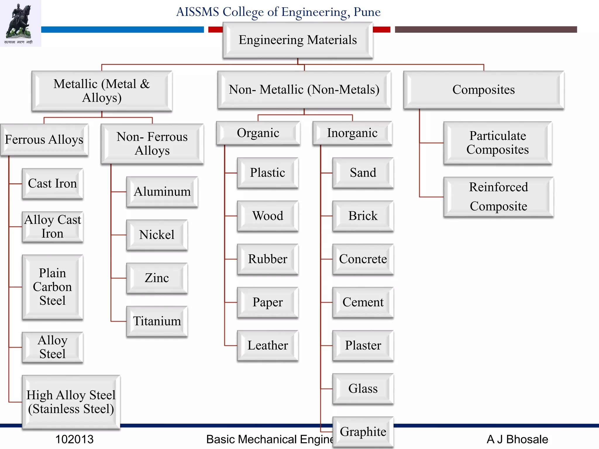


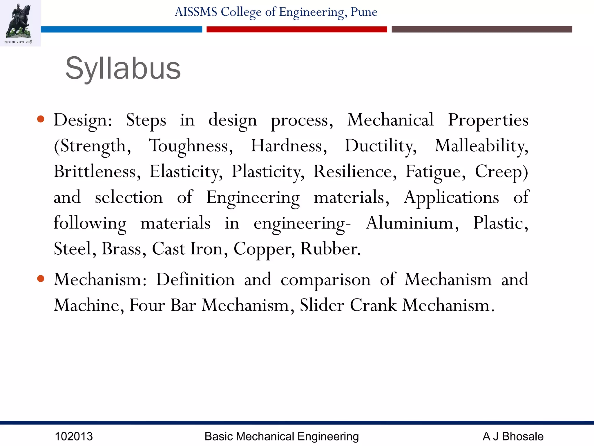
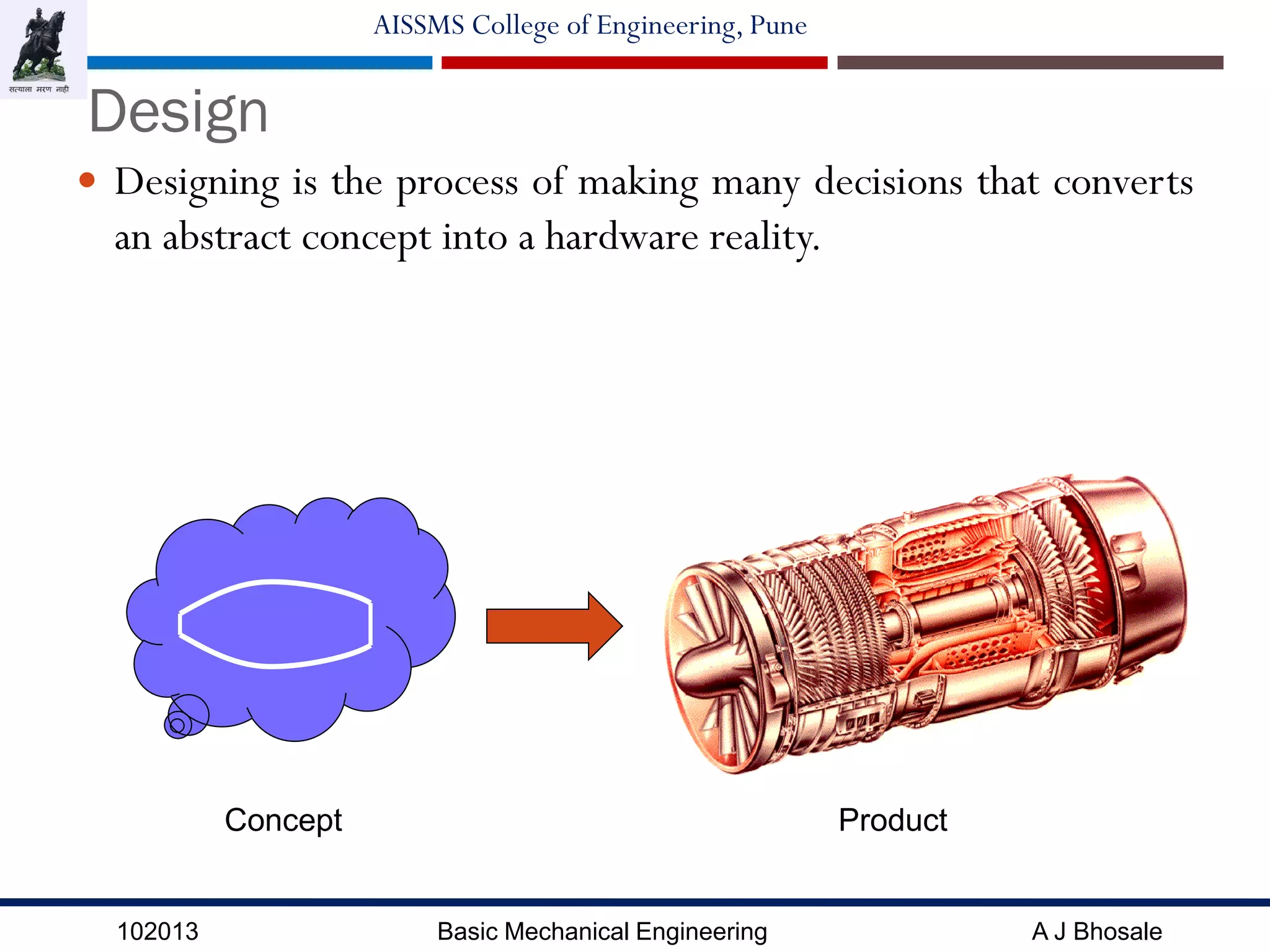
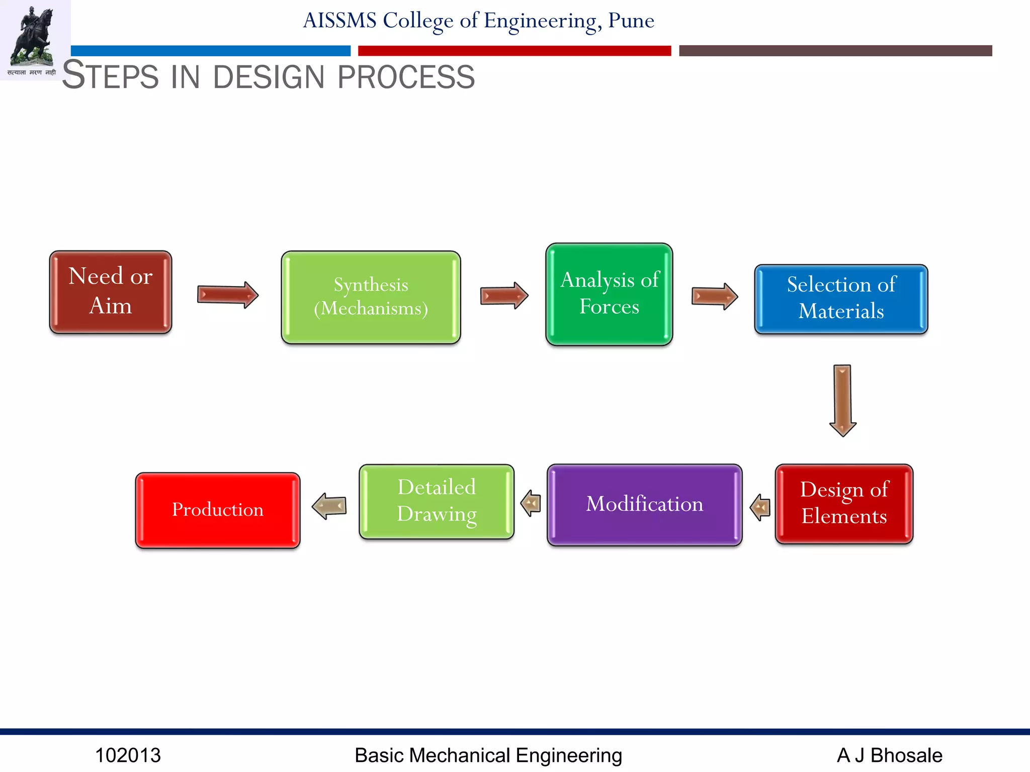
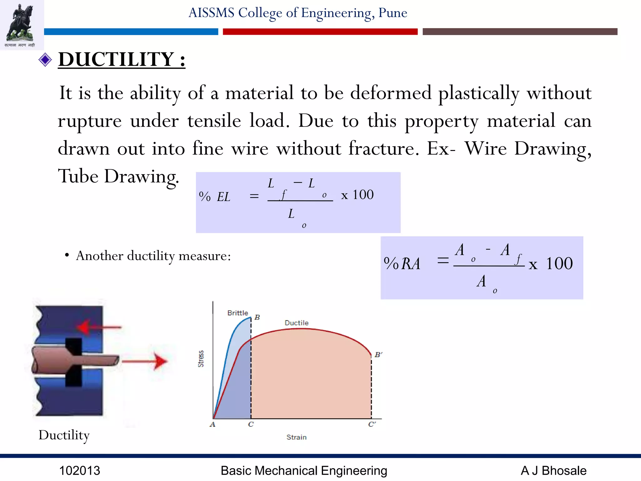
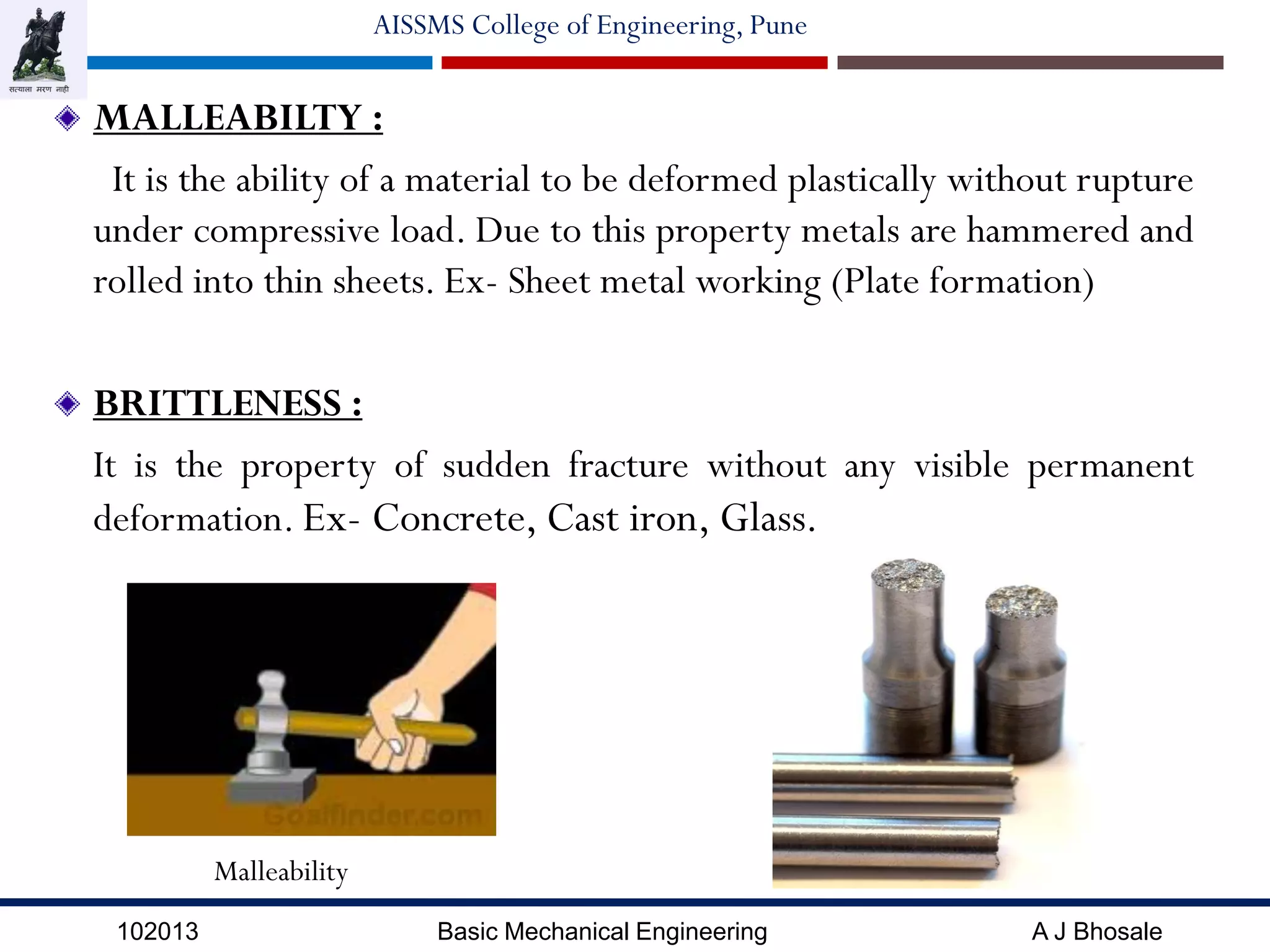
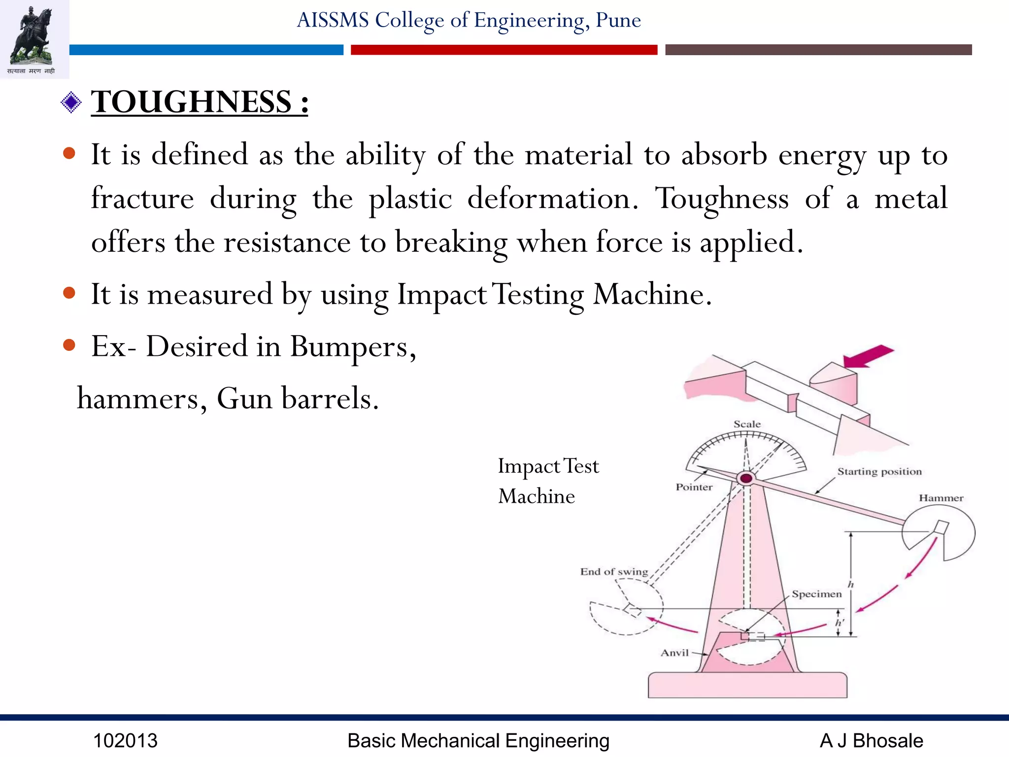
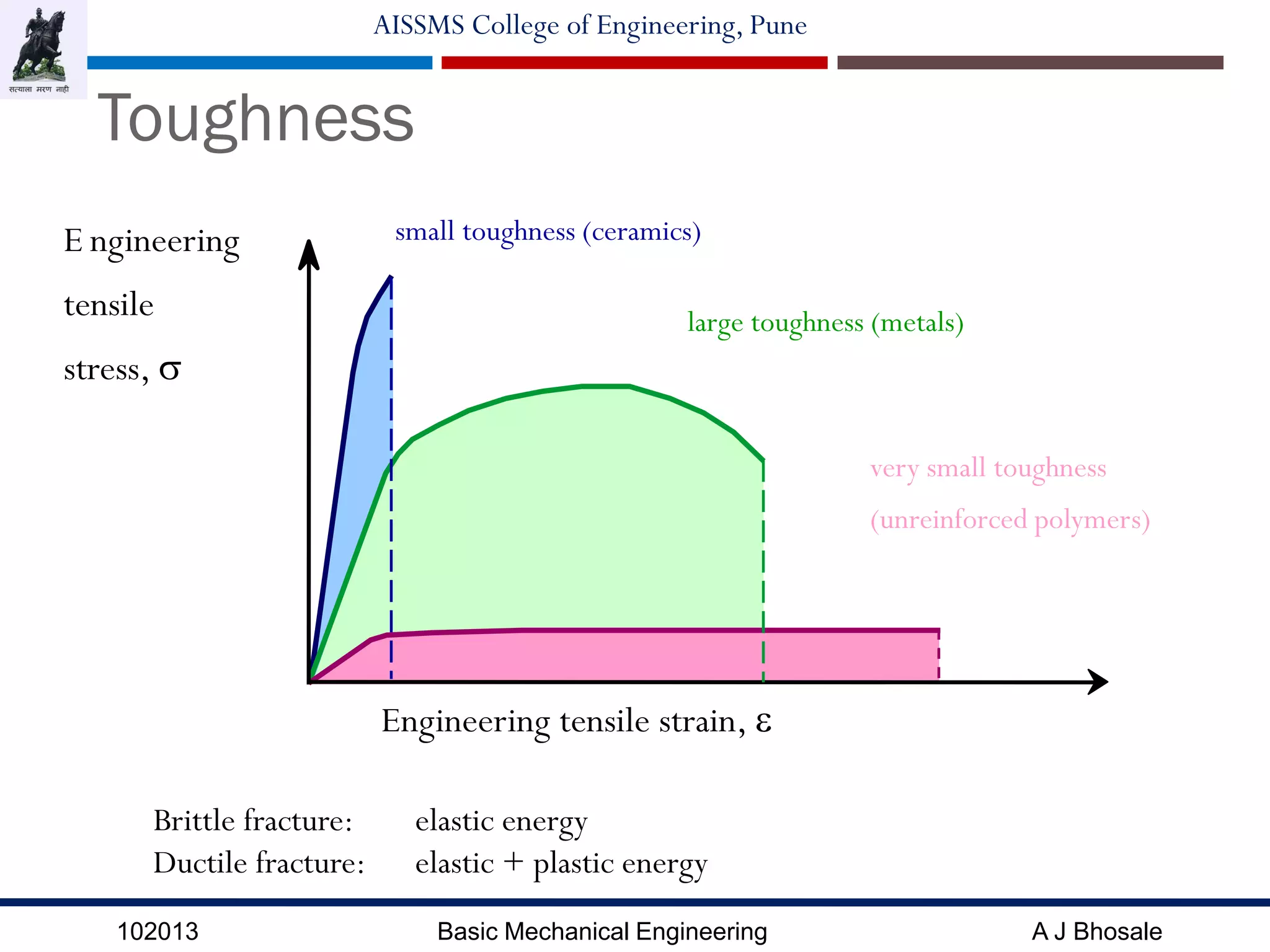
The document outlines the design fundamentals in mechanical engineering, detailing the steps in the design process, which includes defining problems, selecting mechanisms, analyzing forces, and choosing materials. It discusses various design types such as adaptive, developmental, and new design, as well as the mechanical properties of materials like strength, hardness, ductility, and toughness. Additionally, it emphasizes the importance of material selection based on cost, availability, and performance for specific engineering applications.