Download to read offline


![International Research Journal of Engineering and Technology (IRJET) e-ISSN: 2395-0056
Volume: 06 Issue: 03 | Mar 2019 www.irjet.net p-ISSN: 2395-0072
© 2019, IRJET | Impact Factor value: 7.211 | ISO 9001:2008 Certified Journal | Page 3194
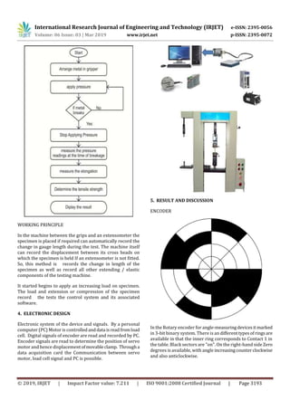
In quadrature Two square waves. By the sign of the A-B
phase angle the direction of rotation is indicated which, in
this case, is negative because A Trails B.
DISPLAY:
On LCD display initially it gives valuesofloadandCHT(cross
head travel).
6. CONCLUSIONS
The construction, design and calibration measurement of a
universal testing machine for tensile tests on thin and soft
materials were discussed.
The performance of the proposed testingmachinefollowing
the work done to calibrate the loadcell, used to obtain the
compliance of the machine, and the data acquisition are
discussed.
REFERENCES
[1] T. Tsuchiya, O. Tabata, J. Sakata (Journal of
Microelectromechanical Systems-1998). Specimen size
effect on tensile strength of surface-micromachined
polycrystalline silicon thin film.
[2] K. Yagi, M. Tokuda, T. Ueda (Micro-
Nanomechatronics and Human Science 2004)
Evaluation of the tensile strength properties by the
difference in the degree of polymerization of PVA gels
[3] Haidong Z, Ikuo Shohji, Masayoshi Shimoda
(IEEE2014). Effect of temperature on tensile properties
of highmelting point Bi system solder.](https://image.slidesharecdn.com/irjet-v6i3618-190904100657/85/IRJET-Data-Acquisition-using-Tensile-Strength-Testing-Machine-4-320.jpg)

This document describes a tensile strength testing machine that was designed to test the strength of textile materials. It discusses the various components of the machine, including the load cell, rotary encoder, microcontroller, analog-to-digital converter (ADC), and other electronic components. The machine is able to automatically record the load and elongation of a specimen as it is placed under increasing tensile stress. The load, elongation, and other data are sent to a computer for analysis. The design of the data acquisition system and electronic components is explained, and the machine is able to accurately measure and record the load-elongation curve of textile specimens during strength testing.