This document summarizes the design and analysis of a wideband microstrip patch antenna employing EBG structures and a partial ground plane. Initially, a simple patch antenna was designed as a baseline, then various modifications were made, including cutting an H-slot in the patch, cutting the patch into a star shape, adding EBG structures, and adding a DGS structure. The proposed antenna design uses EBG structures within the patch and a partial ground plane. Simulation results show it resonates at four frequencies between 2.5-12.9 GHz with return losses between -13.96 to -19.0 dB, indicating a wide bandwidth. The antenna also has an omni-directional radiation pattern and gain of 6.33
Design of Dual Frequency Antenna For Global Positioning systemijsrd.com
In recent years low profile, light weight antennas are preferred for the applications which need mobility. In this research the polygonal-shape Microstrip Single Patch Antenna has been designed for GPS dual resonant frequencies (GPS L1 1.575 GHz & L5 1.176 GHz band). Simulated results for main parameters such as return loss, bandwidth, radiation patterns and gains are also discussed herein. The Designing, Simulation & Optimization of this antenna is done in ADS Software. Result of the simulation shows at 1.575 GHz and 1.176 GHz, the antenna has return loss at -20.862 dB and -14.162 dB respectively. .
Phi shape uwb antenna with band notch characteristicsKiran Ajetrao
In this paper a novel band notch antenna in UWB
frequency range is designed using split rings. Split rings are
overlapped with designed monopole to give phi shape. The slit
gap gives band-notch operation from 5.1GHz to 6.29GHz and
from 4.94GHz to 5.91GHz for SPSSR and SPSCR antennas
respectively. Simulated and measured results are in good
agreement.
Design and simulation of circularly polarized pentagonal-shaped microstrip pa...cscpconf
In wireless communication system antennas play an inherent role. In terms of geometrical shapes
and implementations microstrip patch antennas are versatile in nature. Characteristics like low
gain and smaller bandwidth make single microstrip more popular. Printed type of antenna
which consists of a radiating patch on one side of a dielectric substrate and ground plane on the
other side is a microstrip patch antenna. The intension of exploiting design is to implement a
circularly polarized pentagonal-shaped microstrip patch antenna with a dielectric constant of
2.33, for a dielectric substrate. The antenna is designed and simulated using IE3D
electromagnetic simulator. Circularly polarized pentagonal-shaped microstrip patch antenna has
good CP axial ratio bandwidth and minimum reflection coefficient. The aimed antenna designed
for WLAN applications at RFID frequency of 2.4 GHz in ISM band. The simulation outcomes shows that the designed CP pentagonal shaped microstrip patch antenna gives axial ratio of 0.6023 at 2.38 GHz and CP axial ratio bandwidth of 36MHz with 1.5%.
Design Study of a Miniaturized Multi-layered Antenna-in-package for 2.4 GHZ ...IJECEIAES
This paper proposes a novel miniaturization technique to enhance the radiation properties of small multi-layer patch antenna used in packaged circuits. The multilayered antenna design is composed of three layers with different shapes. An enhancement on the radiation properties has been obtained by optimizing the geometry of the radiated element and the parasitic conductor of the middle layer. The whole design has been implemented on the FR4 substrate with dielectric constant of 4.4, thickness of 1.6 mm and Copper thickness of 5 m. The first layer is a driven element while second and the third layer are parasitic patch elements. The optimized multilayer antenna has a very small size of . Considering the small size of the antenna, a detailed study of the parameter affecting the radiation has been considered to force the antenna to operate at 2.4 GHz band. Miniaturization techniques based on the current distribution have been also taken into account to shift down the resonant frequency and reduces more and more the antenna size at the designed operating frequency. The miniaturized antenna maintains performant radiation characteristics in terms of reflexion coefficient, bandwidth and directivity. All developed antennas are simulated using the commercial Electromagnetic CST Microwave Studio software. Achieved results demonstrate a good performance with low cost and compact size
IJERA (International journal of Engineering Research and Applications) is International online, ... peer reviewed journal. For more detail or submit your article, please visit www.ijera.com
Analysis of Metamaterial Based Microstrip Array Antennaijceronline
Metamaterials have been intensively researched due to their peculiar features such as negative permittivity and/or permeability and ultra-refraction phenomenon. To satisfy the demand of commonly used wireless communication systems, an antenna which can operate at higher frequencies and enhanced characteristics are desirable. The arrangement of all elements is done that they provide an improvement in bandwidth, directivity return loss etc. The frequency response of a metamaterial can be tailored by varying its characteristics. A new metamaterial structure using square and ring split ring resonator is proposed. Using this metamaterial structure, a microstrip patch antenna is designed with enhanced characteristics such as reduction in return lossfrom-20dB to -36dB with tunability is achieved.
Comparative Isolation Techniques of 1x2 MIMO Antenna for 5Gjournal ijrtem
ABSTRACT : In this paper a simple mender line EBG with slotted ground planer 1x2 rectangle patch multi-band antenna is designed and simulated. Presently the communication system provides the ultra wideband internet services. This is possible due to higher data rates and improved spectral efficiency of the communication system. The higher data rates and improved spectral efficiency are achieved by the use of MIMO antenna. MIMO antenna provide a significant increase in data rate and range of link without more bandwidth and power. The main design challenge in MIMO antenna is to attain high isolation between the antenna elements. This paper reviews various decoupling techniques to improve the mutual coupling between the antenna elements.
DESIGN OF A COMPACT CIRCULAR MICROSTRIP PATCH ANTENNA FOR WLAN APPLICATIONS pijans
This paper presents the design of a compact circular microstrip patch antenna for WLAN applications which covers the band 5.15 to 5.825 GHz. The antenna is designed using 1.4mm thick FR-4 (lossy)substrate with relative permittivity 4.4 and a microstrip line feed is used. The radius of the circular patch is chosen as 7.62mm. To reduce the size and enhance the performance of the proposed antenna, a circular slot is loaded on circular patch and a square slot is etched on the ground plane of dimension 30mm×30mm. Design of the antenna is carried out using CST Microsoft Studio Sonimulation Software. The proposed antenna resonates at 5.5 GHz with a wider bandwidth of 702 MHz and it provides low return loss of -31.58 dB, good gain of 3.23 dB and directivity of 4.28 dBi and high efficiency of around 79% against the resonance frequency. The geometry of the proposed circular antenna with reduced size and its various performance parameters such as return loss, bandwidth, VSWR, gain, directivity, efficiency and radiation pattern plots are presented and discussed.
Circular Patch Antenna Performance using EBG StructureIDES Editor
Electromagnetic Band-Gap (EBG) structures are a
popular and efficient technique for microwave applications.
EBG may be combined with microstrip antenna to increase
the diversity gain, the radiation efficiency and/or to suppress
surface waves, to reduce the side lobes of the radiation pattern
and to increase the bandwidth. In this paper, two different
structures will be presented and discussed, which involve: (1)
EBG structure fed by circular patch antenna, and (2) circular
patch antenna surrounded by one row of EBG structure. The
influence of the EBG structure on the radiation patterns is
investigated. The effect of the surface waves is also considered.
Finally, the reduction of the side lobes of the radiation pattern
to increase the bandwidth is presented.
International Journal of Engineering Research and Applications (IJERA) is an open access online peer reviewed international journal that publishes research and review articles in the fields of Computer Science, Neural Networks, Electrical Engineering, Software Engineering, Information Technology, Mechanical Engineering, Chemical Engineering, Plastic Engineering, Food Technology, Textile Engineering, Nano Technology & science, Power Electronics, Electronics & Communication Engineering, Computational mathematics, Image processing, Civil Engineering, Structural Engineering, Environmental Engineering, VLSI Testing & Low Power VLSI Design etc.
A Novel Design of a Miniature Metamaterial Antenna for RFID Reader ApplicationsTELKOMNIKA JOURNAL
In this article, we propose a novel design of a dual band antenna based metamaterial for RFID
applications. The proposed antenna consists of a rectangular patch using inverted u-slot in radiating
element and two split ring resonators loaded in the ground plane. The antenna is printed on an FR4
substrate having athickness of 1.6 mm, permitivitty of 4.4 and loss tanget of 0.025. this antenna is feed by
a micostrip line having caracteristique of 50 Ohms. The designed antenna resonates at the UHF band
around 900Mz with an input impedance of 87MHz and also, resonates at the ISM band around 2.45GHz
with a large bandwidth about 516MHz. The designed antenna is simulated bys using CST and the results
is validated by HFSS. After simulation, a prototype of the proposed antenna is fabricated, and the
measured results show a good agreement with the simulated one.
International Journal of Computational Engineering Research (IJCER) ijceronline
International Journal of Computational Engineering Research(IJCER) is an intentional online Journal in English monthly publishing journal. This Journal publish original research work that contributes significantly to further the scientific knowledge in engineering and Technology
In this paper a compact, flexible, Multiband antenna is designed. It is having flexible Substrate of photographic paper which makes the antenna conformal. The antenna with two U slots cut in radiating patch is offset fed by microstrip lines gives the multiple bands of WLAN/WIMAX Application and two parasitic Elements improves the bandwidth of a typical microstrip antenna. The Measured results shows that the antenna resonates between Frequency band 2.10-2.95 GHz, 3.35-3.54 GHz and 5.04-6.0Hz.which are used for application such as Bluetooth, Wi-Fi, Zigbee, ISM 2.4GHz,WLAN WiMAX, and WLAN 5.2GHz.
Reduction of Mutual Coupling between Closely Spaced Microstrip Antennas Array...TELKOMNIKA JOURNAL
Reducing mutual coupling is a key research area in design of compact microstrip antennas
arrays. To minimize the overall size of the antennas arrays, the distance between them must be very
small, as a result a strong mutual coupling is appears. Periodic structures can help to design a low profile
of antennas arrays and enable to improve their performances by the suppression of surface waves
propagation in a given frequency range. This paper proposes a novel configuration of mushroom-like
electromagnetic band-gap (2D-EBG) structure created by microstrip technology placed between two
antennas arrays to reduce the mutual coupling more than -33.24dB. When 13×2 EBG structures are used,
the mutual coupling reduces to -59.36dB at the operation frequency 5.8GHz of the antennas arrays. A
26.12dB mutual coupling reduction is achieved, which proves that the surface wave is suppressed. The
proposed configuration is designed, optimized, and miniaturized by using electromagnetic software CST
Microwave Studio. The measured results show that there is a good agreement with the computed results.
Design and Analysis of Microstrip Antenna for CDMA Systems CommunicationIOSR Journals
This paper proposes a newly designed microstrip patch antennas (MSA) for wireless application
(CDMA Systems). The designed single antenna E-shaped patch antenna. Two parallel slots are in corporated
into the patch of a microstrip antenna to expand it bandwidth, and designed antenna operates in the frequency
range of 1.85 to 1.99 GHz. The antenna is designed using air as a dielectric substrate between the ground plane
and substrate patch antenna. IE3D is a full-wave electromagnetic simulator based on the method of moments
(MoM) technique. It has been widely used in the design of MICs, RFICs, patch antennas, wire antennas, and
other RF/wireless antennas. It can be used to calculate and plot the S parameters, VSWR, current distributions
as well as the radiation patterns. The results obtained for each patch were 2D and 3D view of patch, Directivity,
Gain, beam width and other such parameters, true and mapped 3D radiation pattern, and 2D polar radiation
pattern. The antenna successfully achieves the exhibit a broad impedance bandwidth of 27 % (at VSWR < 2)
with respect to the center frequency of 1.9 GHz is designed, fabricated, and finally measured on Spectrum
analyzer. The radiation pattern and directivity are also presented.. Gain maximum achievable is 3 dBi and good
return loss (S11 parameters) of -30 dB is achieved along with broadside radiation pattern.
Performance Improvement of Microstrip antenna using Fractal EBG structure and...iosrjce
IOSR Journal of Electrical and Electronics Engineering(IOSR-JEEE) is a double blind peer reviewed International Journal that provides rapid publication (within a month) of articles in all areas of electrical and electronics engineering and its applications. The journal welcomes publications of high quality papers on theoretical developments and practical applications in electrical and electronics engineering. Original research papers, state-of-the-art reviews, and high quality technical notes are invited for publications.
The Microstrip antenna has been commercially used in many applications, such as direct broadcast
satellite service, mobile satellite communications, global positioning system, medical hyperthermia usage,
etc. The patch antenna of the size reduction at a given operating frequency is obtained. Mobile personal
communication systems and wireless computer networks are most commonly used nowadays and they are
in need of antennas in different frequency bands. In regulate to without difficulty incorporate these
antennas into individual systems, a micro strip scrap transmitter have been preferred and intended for a
convinced divergence. There is also an analysis of radiation pattern, Gain of the antenna, Directivity of the
antenna, Electric Far Field. The simulations results are obtained by using electromagnetic simulation
software called feko software are presented and discussed.
Circular Shape , Dual Band proximity feed UWB AntennaAmitesh Raikwar
Abstract:- This paper presents novel proximity feed, microstrip antenna with dual band operative frequency and having ultra wide bandwidth with center frequency at 3GHz. This Circular shaped microstrip antenna offers a dual band. This paper suggests an alternative approach in enhancing the band width of microstrip antenna for the wireless application operating at a frequency of 3 GHz. A bandwidth enhancement of more than 21% was achieved. The measured results have been compared with the simulated results using software IE3D version-14.0.
MINIATURISATION OF PATCH ANTENNA USING NOVEL FRACTAL GEOMETRYIAEME Publication
In the Field of low profile antennamicro strip patch antennas have attracted many researchers due to small sizeand low cost of fabrication. One of trending member of new designs is Fractalantenna. Fractal shapes are recursive/repetitive self-similar geometries, dueto this self-similarity they can provide high gain, multiband, widebandsolutions and design miniature antenna. Fractal shapes are widely used incomputing, analysis and design; recent trends suggest positive outcomes ofusing fractal shapes in electromagnetics and communication system. In thispaper Jerusalem cube fractal shape is introduced in probe fed conventionalpatch antenna for L1 band. A dual band antenna resonating at 1.41 GHz (L) and3.37 (S) GHz, band is constructed using said fractal shape.
DESIGN OF A COMPACT CIRCULAR MICROSTRIP PATCH ANTENNA FOR WLAN APPLICATIONSpijans
This paper presents the design of a compact circular microstrip patch antenna for WLAN applications
which covers the band 5.15 to 5.825 GHz. The antenna is designed using 1.4mm thick FR-4
(lossy)substrate with relative permittivity 4.4 and a microstrip line feed is used. The radius of the
circular patch is chosen as 7.62mm. To reduce the size and enhance the performance of the proposed
antenna, a circular slot is loaded on circular patch and a square slot is etched on the ground plane of
dimension 30mm×30mm. Design of the antenna is carried out using CST Microsoft Studio Sonimulation
Software. The proposed antenna resonates at 5.5 GHz with a wider bandwidth of 702 MHz and it provides
low return loss of -31.58 dB, good gain of 3.23 dB and directivity of 4.28 dBi and high efficiency of around
79% against the resonance frequency. The geometry of the proposed circular antenna with reduced size
and its various performance parameters such as return loss, bandwidth, VSWR, gain, directivity, efficiency
and radiation pattern plots are presented and discussed.
DESIGN OF A COMPACT CIRCULAR MICROSTRIP PATCH ANTENNA FOR WLAN APPLICATIONSpijans
This paper presents the design of a compact circular microstrip patch antenna for WLAN applications
which covers the band 5.15 to 5.825 GHz. The antenna is designed using 1.4mm thick FR-4
(lossy)substrate with relative permittivity 4.4 and a microstrip line feed is used. The radius of the
circular patch is chosen as 7.62mm. To reduce the size and enhance the performance of the proposed
antenna, a circular slot is loaded on circular patch and a square slot is etched on the ground plane of
dimension 30mm×30mm. Design of the antenna is carried out using CST Microsoft Studio Sonimulation
Software. The proposed antenna resonates at 5.5 GHz with a wider bandwidth of 702 MHz and it provides
low return loss of -31.58 dB, good gain of 3.23 dB and directivity of 4.28 dBi and high efficiency of around
79% against the resonance frequency. The geometry of the proposed circular antenna with reduced size
and its various performance parameters such as return loss, bandwidth, VSWR, gain, directivity, efficiency
and radiation pattern plots are presented and discussed
Design of wide band slotted microstrip patch antenna with defective ground st...IJECEIAES
This paper proposes a microstrip patch antenna (MSPA) in the Ku band for satellite applications. The antenna is small in size with dimensions of about 40 mm×48 mm×1.59 mm and is fed with a coaxial cable of 50 Ω impedance. The proposed antenna has a wide bandwidth of 3.03 GHz ranging from 12.8 GHz to 15.8 GHz. To realize the characteristics of wideband the techniques of defective ground structure (DGS) and etching slots on the radiating element are adopted. The antenna is modeled on the FR4 substrate. A basic circular patch is selected for the design of a dual-frequency operation and in the next step DGS is introduced into the basic antenna and enhanced bandwidth is achieved at both the frequencies. To attain wider bandwidth two slots are etched on the radiating element of which one is a square ring slot and the second one is a circular ring slot. The novelty of the proposed antenna is a miniaturized design and unique response within the Ku band region which is applicable for wireless UWB applications with VSWR <2 and an average gain of 3.6 dB.
In the recent years the improvement in communication systems requires the development of low cost, minimal weight, low profile antennas that are capable of maintaining high performance over a wide spectrum of frequency. This technological trend has focused much effort into the design of a Micro strip patch antenna. In this paper, we designed a rectangular micro strip patch antenna at 3.8GHz and study the effect of antenna dimension Length (L), Width (W), substrate parameter relative dielectric constant (€r ) substrate thickness (h) and radiation pattern using Ansoft HFSS. It even describes the increasing effect of Gain and Directivity. The Proposed antenna also presents the detail steps of designing the micro strip antenna and the simulated result. The feeding technique used to feed the antenna is coaxial probe feeding technique. Micro strip patch antenna is used in many fields like Antenna and mobile communication, Filters, PCB board model and EMC and EMI. Rogers RT/duroid 5880 (tm) substrate with a dielectric constant of approximately 2.2, is a feed and has a partial ground plane. The gain and directivity of the designed antenna is 7.7082 dB and 7.76882dB respectively.
Microstrip Rectangular Monopole Antennas with Defected Ground for UWB Applica...IJECEIAES
This paper presents the design of new compact antennas for ultra wide band applications. Each antenna consists of a rectangular patch fed by 50Ω microstrip transmission line and the ground element is a defected ground structure (DGS). The aim of this study is to improve the bandwidth of these antennas by using DGS and the modification geometry of rectangular structure, which gives new compact antennas for UWB applications. The input impedance bandwidth of the antennas with S11<-10dB is more than 10GHz, from 3GHz to more than 14 GHz. The proposed antennas are investigated and optimized by using CST microwave studio, they are validated by using another electromagnetic solver Ansoft HFSS. The measured parameters present good agreement with simulation. The final antenna structures offer excellent performances for UWB system.
A Triple Band Bow Tie Array Antenna Using Both-sided MIC Technology IJECEIAES
A single-fed linearly polarized 2x2 microstrip bow tie array antenna is proposed. The feed network has microstrip line and slot line where microstrip-slot branch circuit is connected in parallel. The feed network of the array is designed using both-sided M IC Technology to overcome the impedance matching problem of conventional feed networks. The 2x2 half bow tie array antenna is also truncated with spur lines for optimization of antenna performance. The array antenna unit can be realized in very simple and compact structure, as all the antenna elements and the feeding circuit is arranged on a Teflon glass fiber substrate without requiring any external network. The design frequency of the proposed antenna is 5 to 8 GHz (C- Band) and the obtained peak gain is 12.41 dBi. The resultant axial ratio indicates that linear polarization is achieved.
Design and Analysis of Microstrip Antenna for CDMA Systems CommunicationIOSR Journals
Abstract: This paper proposes a newly designed microstrip patch antennas (MSA) for wireless application (CDMA Systems). The designed single antenna E-shaped patch antenna. Two parallel slots are in corporated into the patch of a microstrip antenna to expand it bandwidth, and designed antenna operates in the frequency range of 1.85 to 1.99 GHz. The antenna is designed using air as a dielectric substrate between the ground plane and substrate patch antenna. IE3D is a full-wave electromagnetic simulator based on the method of moments (MoM) technique. It has been widely used in the design of MICs, RFICs, patch antennas, wire antennas, and other RF/wireless antennas. It can be used to calculate and plot the S parameters, VSWR, current distributions as well as the radiation patterns. The results obtained for each patch were 2D and 3D view of patch, Directivity, Gain, beam width and other such parameters, true and mapped 3D radiation pattern, and 2D polar radiation pattern. The antenna successfully achieves the exhibit a broad impedance bandwidth of 27 % (at VSWR < 2) with respect to the center frequency of 1.9 GHz is designed, fabricated, and finally measured on Spectrum analyzer. The radiation pattern and directivity are also presented.. Gain maximum achievable is 3 dBi and good return loss (S11 parameters) of -30 dB is achieved along with broadside radiation pattern. Keywords - Microstrip Patch Antenna; E-shaped, CDMA systems communications; Coaxial Probe feed, IE3D
Design of a Rectangular Microstrip Patch Antenna Using Inset Feed TechniqueIOSR Journals
Abstract : Today in the world of communication systems the most widely researched area is of wireless technology and a study of communication systems is incomplete without an understanding of the operation of the antennas. In the recent years of development in communication systems a need for the development of lightweight, compact and cost-effective antennas that are capable of maintaining high performance over a wide spectrum of frequencies. This technological trend has focused much effort into the design of a Micro strip patch antenna. In this work, the simulation tool of IE3D is used to study the performance and gain of the rectangular Microstrip patch antenna. The design and simulation of patch antennas is widely used in mobile cellular phones today, and our emphasis in this work is on optimization of a 2.4 GHz rectangular Microstrip patch antenna. The return loss and the various gain plots have been studied along with the radiation patterns. Keywords: Gain, Inset feed, Patch antenna, Radiation pattern, Return Loss.
An Analytical Approach for Design of Microstrip Patch (MsP) IJECEIAES
A reliable configuration of electromagnetic interactions for antenna design can yield an effective Microstrip patch (MsP) antenna. During its design, the antenna arrays involve issues with parameters (i.e., space, dimension, shape) adjustment. This problem can be tackled with an analytical approach which can help to bring better idea to design the antenna aaray. However, the realistic designs of antenna array are quite expensive while extracting computational accuracy. Thus, to have low cost computational accuracy various meta-heuristic (generic algorithm, partical swarm optimizarion) approaches are used and are considered as effective one in handling the pattern synthesis problems. Howeever, the use of meta-heuristic approaches demands thousands of functions to analyze the antenna design. This manuscript introduces an analytical approach for MsP antenna desing using MATLAB that brings optimization in handling the side lobes and optimizing the reflection as well as radiation responses. The outcomes of the design were analyzed with respect to reflection, radiation coefficients, side lobes and found effective at 10GHz as per computational cost is concern.
IJERA (International journal of Engineering Research and Applications) is International online, ... peer reviewed journal. For more detail or submit your article, please visit www.ijera.com
This paper presents the Microstrip patch antenna for WLAN applications with planar geometry and it consists of a defected ground (DGS), a feed, a substrate, and a patch. The design with DGS has been analyzed taking different dimensions of H Slot and achieve optimized dimensions with the help of CST, Microwave Studio commercial software for WLAN band at 5.20 GHz frequency with corresponding bandwidth of 310 MHz to optimize antenna’s properties. Results show that the final designed antenna has favorable characteristics at this frequency.
Similar to Design and Analysis of Wideband Microstip Patch Antenna Employing EBG and Partial Ground Plane (20)
NO1 Uk best vashikaran specialist in delhi vashikaran baba near me online vas...Amil Baba Dawood bangali
Contact with Dawood Bhai Just call on +92322-6382012 and we'll help you. We'll solve all your problems within 12 to 24 hours and with 101% guarantee and with astrology systematic. If you want to take any personal or professional advice then also you can call us on +92322-6382012 , ONLINE LOVE PROBLEM & Other all types of Daily Life Problem's.Then CALL or WHATSAPP us on +92322-6382012 and Get all these problems solutions here by Amil Baba DAWOOD BANGALI
#vashikaranspecialist #astrologer #palmistry #amliyaat #taweez #manpasandshadi #horoscope #spiritual #lovelife #lovespell #marriagespell#aamilbabainpakistan #amilbabainkarachi #powerfullblackmagicspell #kalajadumantarspecialist #realamilbaba #AmilbabainPakistan #astrologerincanada #astrologerindubai #lovespellsmaster #kalajaduspecialist #lovespellsthatwork #aamilbabainlahore#blackmagicformarriage #aamilbaba #kalajadu #kalailam #taweez #wazifaexpert #jadumantar #vashikaranspecialist #astrologer #palmistry #amliyaat #taweez #manpasandshadi #horoscope #spiritual #lovelife #lovespell #marriagespell#aamilbabainpakistan #amilbabainkarachi #powerfullblackmagicspell #kalajadumantarspecialist #realamilbaba #AmilbabainPakistan #astrologerincanada #astrologerindubai #lovespellsmaster #kalajaduspecialist #lovespellsthatwork #aamilbabainlahore #blackmagicforlove #blackmagicformarriage #aamilbaba #kalajadu #kalailam #taweez #wazifaexpert #jadumantar #vashikaranspecialist #astrologer #palmistry #amliyaat #taweez #manpasandshadi #horoscope #spiritual #lovelife #lovespell #marriagespell#aamilbabainpakistan #amilbabainkarachi #powerfullblackmagicspell #kalajadumantarspecialist #realamilbaba #AmilbabainPakistan #astrologerincanada #astrologerindubai #lovespellsmaster #kalajaduspecialist #lovespellsthatwork #aamilbabainlahore #Amilbabainuk #amilbabainspain #amilbabaindubai #Amilbabainnorway #amilbabainkrachi #amilbabainlahore #amilbabaingujranwalan #amilbabainislamabad
Courier management system project report.pdfKamal Acharya
It is now-a-days very important for the people to send or receive articles like imported furniture, electronic items, gifts, business goods and the like. People depend vastly on different transport systems which mostly use the manual way of receiving and delivering the articles. There is no way to track the articles till they are received and there is no way to let the customer know what happened in transit, once he booked some articles. In such a situation, we need a system which completely computerizes the cargo activities including time to time tracking of the articles sent. This need is fulfilled by Courier Management System software which is online software for the cargo management people that enables them to receive the goods from a source and send them to a required destination and track their status from time to time.
Hybrid optimization of pumped hydro system and solar- Engr. Abdul-Azeez.pdffxintegritypublishin
Advancements in technology unveil a myriad of electrical and electronic breakthroughs geared towards efficiently harnessing limited resources to meet human energy demands. The optimization of hybrid solar PV panels and pumped hydro energy supply systems plays a pivotal role in utilizing natural resources effectively. This initiative not only benefits humanity but also fosters environmental sustainability. The study investigated the design optimization of these hybrid systems, focusing on understanding solar radiation patterns, identifying geographical influences on solar radiation, formulating a mathematical model for system optimization, and determining the optimal configuration of PV panels and pumped hydro storage. Through a comparative analysis approach and eight weeks of data collection, the study addressed key research questions related to solar radiation patterns and optimal system design. The findings highlighted regions with heightened solar radiation levels, showcasing substantial potential for power generation and emphasizing the system's efficiency. Optimizing system design significantly boosted power generation, promoted renewable energy utilization, and enhanced energy storage capacity. The study underscored the benefits of optimizing hybrid solar PV panels and pumped hydro energy supply systems for sustainable energy usage. Optimizing the design of solar PV panels and pumped hydro energy supply systems as examined across diverse climatic conditions in a developing country, not only enhances power generation but also improves the integration of renewable energy sources and boosts energy storage capacities, particularly beneficial for less economically prosperous regions. Additionally, the study provides valuable insights for advancing energy research in economically viable areas. Recommendations included conducting site-specific assessments, utilizing advanced modeling tools, implementing regular maintenance protocols, and enhancing communication among system components.
Saudi Arabia stands as a titan in the global energy landscape, renowned for its abundant oil and gas resources. It's the largest exporter of petroleum and holds some of the world's most significant reserves. Let's delve into the top 10 oil and gas projects shaping Saudi Arabia's energy future in 2024.
Vaccine management system project report documentation..pdfKamal Acharya
The Division of Vaccine and Immunization is facing increasing difficulty monitoring vaccines and other commodities distribution once they have been distributed from the national stores. With the introduction of new vaccines, more challenges have been anticipated with this additions posing serious threat to the already over strained vaccine supply chain system in Kenya.
COLLEGE BUS MANAGEMENT SYSTEM PROJECT REPORT.pdfKamal Acharya
The College Bus Management system is completely developed by Visual Basic .NET Version. The application is connect with most secured database language MS SQL Server. The application is develop by using best combination of front-end and back-end languages. The application is totally design like flat user interface. This flat user interface is more attractive user interface in 2017. The application is gives more important to the system functionality. The application is to manage the student’s details, driver’s details, bus details, bus route details, bus fees details and more. The application has only one unit for admin. The admin can manage the entire application. The admin can login into the application by using username and password of the admin. The application is develop for big and small colleges. It is more user friendly for non-computer person. Even they can easily learn how to manage the application within hours. The application is more secure by the admin. The system will give an effective output for the VB.Net and SQL Server given as input to the system. The compiled java program given as input to the system, after scanning the program will generate different reports. The application generates the report for users. The admin can view and download the report of the data. The application deliver the excel format reports. Because, excel formatted reports is very easy to understand the income and expense of the college bus. This application is mainly develop for windows operating system users. In 2017, 73% of people enterprises are using windows operating system. So the application will easily install for all the windows operating system users. The application-developed size is very low. The application consumes very low space in disk. Therefore, the user can allocate very minimum local disk space for this application.
Water scarcity is the lack of fresh water resources to meet the standard water demand. There are two type of water scarcity. One is physical. The other is economic water scarcity.
Sachpazis:Terzaghi Bearing Capacity Estimation in simple terms with Calculati...Dr.Costas Sachpazis
Terzaghi's soil bearing capacity theory, developed by Karl Terzaghi, is a fundamental principle in geotechnical engineering used to determine the bearing capacity of shallow foundations. This theory provides a method to calculate the ultimate bearing capacity of soil, which is the maximum load per unit area that the soil can support without undergoing shear failure. The Calculation HTML Code included.
Welcome to WIPAC Monthly the magazine brought to you by the LinkedIn Group Water Industry Process Automation & Control.
In this month's edition, along with this month's industry news to celebrate the 13 years since the group was created we have articles including
A case study of the used of Advanced Process Control at the Wastewater Treatment works at Lleida in Spain
A look back on an article on smart wastewater networks in order to see how the industry has measured up in the interim around the adoption of Digital Transformation in the Water Industry.
Student information management system project report ii.pdfKamal Acharya
Our project explains about the student management. This project mainly explains the various actions related to student details. This project shows some ease in adding, editing and deleting the student details. It also provides a less time consuming process for viewing, adding, editing and deleting the marks of the students.
Immunizing Image Classifiers Against Localized Adversary Attacksgerogepatton
This paper addresses the vulnerability of deep learning models, particularly convolutional neural networks
(CNN)s, to adversarial attacks and presents a proactive training technique designed to counter them. We
introduce a novel volumization algorithm, which transforms 2D images into 3D volumetric representations.
When combined with 3D convolution and deep curriculum learning optimization (CLO), itsignificantly improves
the immunity of models against localized universal attacks by up to 40%. We evaluate our proposed approach
using contemporary CNN architectures and the modified Canadian Institute for Advanced Research (CIFAR-10
and CIFAR-100) and ImageNet Large Scale Visual Recognition Challenge (ILSVRC12) datasets, showcasing
accuracy improvements over previous techniques. The results indicate that the combination of the volumetric
input and curriculum learning holds significant promise for mitigating adversarial attacks without necessitating
adversary training.
Immunizing Image Classifiers Against Localized Adversary Attacks
Design and Analysis of Wideband Microstip Patch Antenna Employing EBG and Partial Ground Plane
1. IOSR Journal of Electronics and Communication Engineering (IOSR-JECE)
e-ISSN: 2278-2834,p- ISSN: 2278-8735.Volume 10, Issue 1, Ver. 1 (Jan - Feb. 2015), PP 55-59
www.iosrjournals.org
DOI: 10.9790/2834-10115559 www.iosrjournals.org 55 | Page
Design and Analysis of Wideband Microstip Patch Antenna
Employing EBG and Partial Ground Plane
Gurpreet Singh Saini1
, Amandeep Singh2
1
(Department ECE, Arni University, HP, India)
2
(Department ECE, CTIEMT Jalandhar, Punjab, India)
Abstract: In this paper a new technique to widen bandwidth of a microstrip patch antenna is proposed. For the
proposed antenna, shape and dimensions are chosen for obtaining wide bandwidth and small size. First a
simple patch antenna is designed for the test, and then a microstrip patch antenna employing EBG structures
with partial ground is demonstrated. This proposed design exhibits wide band behavior of resonant frequencies
2.5 GHz, 7.2 GHz, 10.6 GHz and 12.9 GHz frequencies with good return loss values -13.96 dB,-12.08 dB, -13.8
dB and -19.0 dB respectively. The design is analyzed with Ansoft HFSS 13.0 electromagnetic field solver.
Keywords: EBG (Electromagnetic Band Gap), Microstrip Patch Antenna (MPA),
I. Introduction
Microstrip patch antenna is promising to be a good candidate for future wireless technologies, as
wireless communication industry is adding leaps and bounds. With the rapid growth of wireless markets [mobile
communication, wireless local area network (WLAN) networking, global positioning system (GPS) services,
and radio-frequency identification (RFID) applications], radio-frequency (RF) engineers are facing continuing
challenges of small-volume, wide-bandwidth, power efficient, and low-cost system designs. To achieve the
desired goal the level of integration and miniaturization of antenna is also increasing and their comes the need to
design a conformal small antenna for wideband applications. Microstrip patch antenna are low profile, light
weight, easy to feed and have good radiation pattern, easy to manufacture and hence they are the demand of the
new era of wireless technology. A Microstrip patch antenna in its simplest form consists of a radiating patch on
one side of a dielectric substrate and a ground plane on the other side. However, at the same time they have
disadvantages of low efficiency, narrow bandwidth and surface wave losses.
Due to recent research in the electromagnetic band gap (EBG) structure for antenna application to
suppress the surface wave losses and improve the radiation performance of the antenna. When source signal is
applied at metal ground plane and patch, the electromagnetic waves will be radiated. This radiation will not be
perfect as there are some losses due to dielectric substrate and to minimize these losses we will insert EBG
structures with microstrip patch antenna. Electromagnetic band gap structures are defined as artificial periodic
or sometimes non-periodic objects or say that dielectric materials and metallic conductors that prevent the
propagation of electromagnetic waves in a specified band of frequency for all incident angles and all
polarization states. At present time, there is a need of smaller and broad bandwidth antennas. This can be
achieved by fabrication of antenna on thick piece of high permittivity substrate. The main disadvantage is that,
the unwanted substrate modes begin to form and propagate towards the edges of the substrate, which have a
deadly effect on the antenna radiation pattern[13].
The innovation in the field Microstrip patch antenna is succeeding day to day As Jiejun Zhang [1]
presented a paper based on RCS reduction of patch array antenna by electromagnetic band-gap structure. The
results show that the RCS can be significantly reduced when the band-gap of the EBG is designed out of the
band of antenna, and the performance of the antenna has no degradation. Nargis Aktar [2] proposed enhanced
gain and bandwidth of patch antenna using EBG substrates. Due to the presence of the EBG structure in the
dielectric substrates, the electromagnetic band gap is created that reduces the surface waves considerably.
Jatinderpal Singh [3] projected design analysis of a hexaband slot loaded microstrip patch antenna for wireless
applications. The antenna design is suitably recommended for the applications like WLAN (2.44 GHz at -12.29
dB), Radio astronomy (6.48 GHz at -16.43 dB ), Passive sensors (7 GHz at -15.05 dB) and Point to Point
defence system (8.25 GHz at -27.81 dB) wireless applications. José Felipe Almeida [4] demonstrated study of a
microstrip antenna with PBG considering the substrate thickness variation by which improvement of the
efficiency and bandwidth is verified when the substrate thickness is increased. Zhenghua Li [5] anticipated
investigation of patch antenna based on photonic band-gap substrate with heterostructures and realized that
radiation efficiency and return loss is significantly improved. Amandeep Singh [6]proposed design analysis of a
circular polarized slot loaded microstrip patch antenna for multiband applications and is rightfully
recommended for the applications like WLAN (2.44 GHz at -12.29 dB),Radio astronomy (6.48 GHz at -16.43
dB ), Passive sensors (7 GHz at -15.05 dB) and Point to Point. R.N.Tiwari [7] introduced rectangular microstrip
2. Design and Analysis of Wideband Microstip Patch Antenna Employing EBG and Partial ….
DOI: 10.9790/2834-10115559 www.iosrjournals.org 56 | Page
patch antenna with photonic band gap crystal for 60 GHz communications and this antenna gives high
bandwidth and gain with radiation pattern omidirectional in nature. Rachmansyah [8] presented designing and
manufacturing microstrip antenna for wireless communication at 2.4 GHz and found that antenna can be used as
client antenna in computer and workable antenna for wireless fidelity. Sahar Naserzadeh [9] demonstrated
mushroom-like EBG structure for enhancement of circular polarization array antenna performances and results
show that, these techniques cause axial ratio bandwidth enhancement and gain improvement, also it decrease
side lobe levels. Amandeep Singh [10] presented miniaturized wideband aperture coupled microstrip patch
antenna by using inverted U-slot and showed the measured return loss within acceptable range throughout the
band (11.08 GHz–13.25 GHz) and maximum return loss is achieved with proper impedance matching. Jagdish
M. Rathod [11] studied comparative study of microstrip patch antenna for wireless communication application
and realized that good impedance matching condition between the line and patch without any additional
matching elements depends heavily on feeding techniques used. In present work we have proposed an antenna
which exhibits a good value of return loss at four resonant frequencies. The details of the development of the
proposed antenna are available in the next sections.
II. Design Methodology
To design and analyze the proposed antenna, High Frequency structure Simulator (HFSS)
electromagnetic software tool is utilized. HFSS is a high performance full-wave electromagnetic (EM) field
solver for arbitrary 3D volumetric passive device modeling. It integrates visualization, simulation, solid
modeling and automation in an easy-to-learn environment where solutions to 3D EM problems are quickly and
accurately obtained [12]. Ansoft HFSS employs the Finite Element Method (FEM), adaptive meshing, and
brilliant graphics to give unparalleled performance and insight to all 3D EM problems. Ansoft HFSS can be
used to calculate parameters such as S-Parameters, Resonant Frequency, and Fields. HFSS is an interactive
simulation system whose basic mesh element is a tetrahedron thus allowing us to solve any arbitrary 3D
geometry.
III. Antenna Design
The structure of the proposed antenna design has been studied in this section. Fig 1 represents the
architectural view of the proposed antenna. This antenna is made up of three layers in which first layer
comprises the conductive ground plane, second layer comprises the substrate i.e. dielectric material and third
layer comprises the conductive patch. In the proposed design electronic band gap structures are made in the
substrate in the shapes of cubes, patch is cut in the form star and a partial ground plane is employed. The
different shapes by cutting slots in the proposed antenna design have been decided after proper parametric
analysis to achieve the appropriate microstrip patch antenna that can be used for wideband wireless
applications.
Figure 1: Geometry of the proposed microstrip patch antenna
In the proposed design, slots are cut in the metallic patch to enhance its bandwidth so that this
microstrip patch antenna can be used for wideband applications. The dimensions of the patch play a vital role in
deciding the overall characteristics of the analyzed microstrip patch antenna. Dimensions of the proposed
antenna are optimized by iterative trials on the software. Length and width of the ground plane is half in size as
compared to the substrate. In the substrate of proposed design sixteen cube slots are cut in the of 1 m3
to
integrate electromagnetic band gap structures. Patch of the proposed antenna is shown by orange color in figure
1 and in this star shaped slot is cut to enhance the bandwidth and gain of the antenna. This antenna is fed with
3. Design and Analysis of Wideband Microstip Patch Antenna Employing EBG and Partial ….
DOI: 10.9790/2834-10115559 www.iosrjournals.org 57 | Page
microstrip feed line technique as this is simple to match by controlling the inset feed position.All the important
design parameters of the proposed antenna are represented in form of Ttable 1 which clearly indicate the actual
physical interpretation of the proposed design.
Antenna Parameters
εr 2,2 L 32.00 mm
W 31.00 mm L1 10.00 mm
W1 2.00 mm L2 3.80 mm
W2 24.00 mm L3 3.73 mm
W3 2.82 mm L4 3.26 mm
W4 5.00 mm L5 3.35 mm
W5 12.42 mm L6 2.00 mm
W6 2.69 mm L7 2.00 mm
W7 2.69 mm L8 6.40 mm
W8 2.00 mm L9 12.00 mm
W9 3.75 mm
Table 1: Design parameters of the proposed antenna
IV. Results And Discussions
To check the performance of the proposed antenna different microstrip patch antenna are designed and
their parametric analysis is done which is shown in Table 2 as well as through a graph between frequency and
return loss shown in fig 2. Initially a simple patch antenna is intended which resonates at operating frequencies
2.3 GHz, 7.2 GHz, 10.8 GHz and 12.8 GHz frequencies with return loss values -3.76 dB, -6.2 dB, -8.35 dB and
-10.7 dB respectively shown by black line in fig 2.Characteristics of antenna changes when H slot is cut in patch
of antenna, it resonates at 2.3 GHz, 6.9 GHz, 10.0 GHz and 12.6 GHz exhibits return loss of -12.1 dB, -6.9 dB, -
9.29 dB and -16.66 dB respectively, represented by orange line in fig 2. Further patch is cut in the form star,
then antenna resonates at operating frequencies 2.3 GHz, 6.7 GHz, 10.0 GHz and 13.0 GHz frequencies with
return loss values -12.4 dB,-12.0 dB, -12.0 dB and -9.0 dB respectively shown by sky blue line in fig 2. Further
EBG(electronic band gap) structures is employed in the patch of the antenna, it exhibits resonant operating
frequencies at 2.3 GHz, 6.3 GHz, 10.0 GHz and 12.1 GHz exhibits return loss of -11.75 dB, -10.8 dB, -18.0 dB
and -10.59 dB respectively, represented by pink line in fig 2. In the next design DGS structure is engaged in the
patch of the antenna, and the results show that antenna resonates on operating frequencies at 2.3 GHz, 6.8 GHz,
10.8 GHz and 12.5 GHz frequencies with return loss values -11.7 dB, -6.8 dB, -10.2 dB and -15.3 dB
respectively, represented by green line in fig 2.
Antenna type Fr in GHz S11 in dB Fr in GHz S11 in dB Fr in GHz S11 in dB Fr in GHz S11 in dB
Simple Patch 2.3 -3.76 7.2 -6.2 10.8 -8.35 12.8 -10.7
Patch with H slot 2.3 -12.1 6.9 -6.9 10.0 -9.29 12.5 -16.66
Patch with star slot 2.3 -12.4 6.7 -12.0 10.0 -12.0 13.0 -9.0
Patch with EBG 2.3 -11.75 6.3 -10.1 10.0 -18.0 12.1 -10.59
Patch with DGS 2.3 -11.7 6.8 -6.8 10.8 -10.2 12.5 -15.3
Patch with EBG and
partial ground
2.5 -13.96 7.2 -12.08 10.6 -13.8 12.9 -19.0
Table 2: Resonant frequencies and return loss characteristics at different values for the different shapes of
antenna
Figure 2: Return Loss versus operating frequency characteristics for the proposed antenna by employing
different shapes in the patch
4. Design and Analysis of Wideband Microstip Patch Antenna Employing EBG and Partial ….
DOI: 10.9790/2834-10115559 www.iosrjournals.org 58 | Page
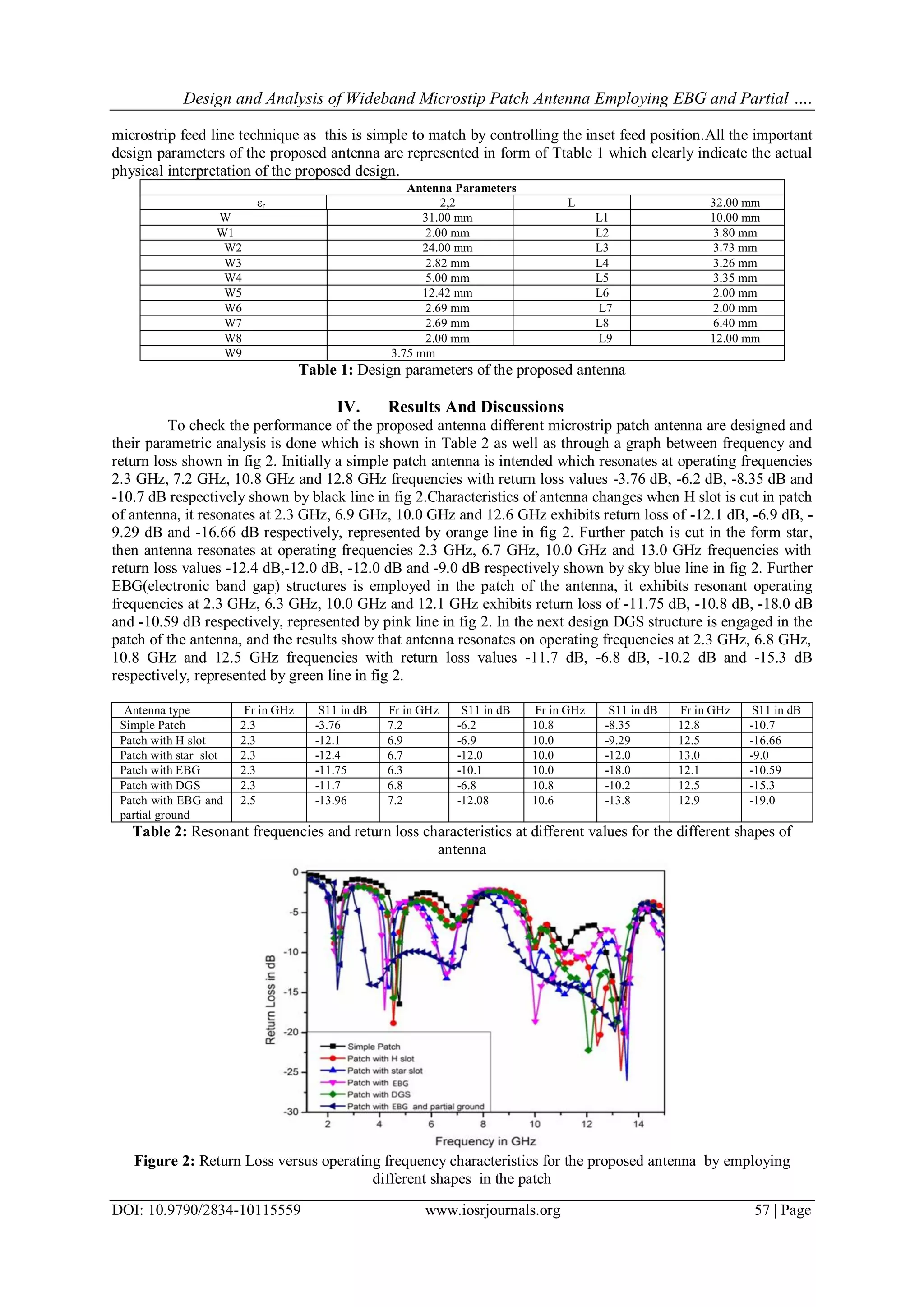
Finally we have proposed an antenna design employing EBG structures in patch and using partial
ground plane and this antenna exhibits on operating frequencies at 2.5 GHz, 7.2 GHz, 10.6 GHz and 12.9 GHz
frequencies with return loss values -13.96 dB,-12.08 dB, -13.8 dB and -19.0 dB respectively. This is represented
by dark blue curve plot of fig 2.Lastly, from the above parametric observations, we have choose the antenna
design using EBG structures in patch and using partial ground plane. The analysis of antenna is generally based
upon two broad categories, one is input parameters and another is output parameters. Return loss characteristics
as shown in fig 2 representing the input characteristics and gain of the antenna comes under the output
characteristics. Therefore, it is important to analyze the gain response of the proposed antenna to confirm the
antenna as a good radiator. From the above analysis, it can be seen that for the proposed antenna design that is
microstrip using EBG structures and partial ground plane resonates absolutely at specific values of return loss as
shown in Table 2.
Figure 3: 3D gain plot of the proposed antenna design
Moreover, it can be seen in the fig 2 that the proposed antenna employing EBG structures and partial
ground plane which is represented by blue line resonates below -10 dB for almost all frequencies between 2
GHz and 13 GHz which makes this proposed antenna to be used for the wideband wireless applications. Fig 3 is
representing the 3D gain plot of the proposed antenna that it radiates almost equally in all directions normal to
the patch means it exhibits Omni directional characteristics. The gain of 6.33 dBi is obtained from the antenna
which is very sufficient for the small distance wireless applications.
V. Conclusion
In this paper antenna with different shapes are designed and their parametric analysis has be done.
Finally the proposed antenna employing EBG structures in patch and using partial ground plane is analyzed to
know the characteristics of antenna. It has observed that the proposed antenna is multiband in nature and
resonant exhibits on operating frequencies at 2.5 GHz, 7.2 GHz, 10.6 GHz and 12.9 GHz frequencies with
return loss values -13.96 dB,-12.08 dB, -13.8 dB and -19.0 dB respectively. It is found that proposed antenna
has good value of gain of 6.33 dBi and can be used for various wideband applications such as WLAN, Radio
astronomy, Passive sensors, Wi-MAX band, Wireless local loop and Point to Point defence system wireless
applications.
References
[1]. Jiejun Zhang, Junhong Wang, Meie Chen, and Zhan Zhang “RCS Reduction of Patch Array Antenna by Electromagnetic Band-Gap
Structure” IEEE Antennas and Wireless Propagation Letters, VOL. 11, 2012.
[2]. Mst. Nargis Aktar, Muhammad Shahin Uddin, "Enhanced Gain And Bandwidth Of Patch Antenna Using EBG Substrates,”
International Journal of Wireless & Mobile Networks (IJWMN), Vol. 3, No. 1, February 2011.
[3]. Jatinderpal Singh, Amandeep Singh and Nancy Gupta, “Design Analysis of a Hexaband Slot Loaded Microstrip Patch Antenna
using ANN,” International Journal of Computer Applications, vol. 101, No. 14, pp. 7-12, 2014
[4]. Jose Felipe Almeida, Carlos Leonidas da S. S. Sobrinho and Ronaldo Oliveira dos Santos,“Study of a Microstrip Antenna with PBG
Considering the Substrate Thickness Variation” Depto. of Elect. and Comp. Eng., Federal University of Pará (UFPA), PO Box
8619, Zip Code: 66073-900,Belém, PA, Brazil.
[5]. Zhenghua Li, Yan Ling Xue, Tinggen Shen “Investigation of Patch Antenna Based on Photonic Band-gap Substrate with
Heterostructures” 973 Key Program from the Ministry of Science and Technology of China (No. 2006CB921100).
[6]. Jatinderpal Singh, Amandeep Singh and Nancy Gupta, “Design Analysis of a Circular Polarized Slot Loaded Microstrip Patch
Antenna for Multiband Applications,” International Journal of Information & Communication Technology, vol. 2, pp. 35-40, 2014.
[7]. R. N. Tiwari, P. Kumar, and Nitasha Bisht “Rectangular Microstrip Patch Antenna with Photonic Band Gap Crystal for 60 GHz
Communications” PIERS Proceedings, Suzhou, China, September 12-16, 2011.
5. Design and Analysis of Wideband Microstip Patch Antenna Employing EBG and Partial ….
DOI: 10.9790/2834-10115559 www.iosrjournals.org 59 | Page
[8]. Rachmansyah, Antonius Irianto, and A. Benny Mutiara “Designing and Manufacturing Microstrip Antenna for Wireless
Communication at 2.4 GHz” International Journal of Computer and Electrical Engineering, Vol. 3, No. 5, October 2011.
[9]. Sahar naserzadeh, Faroukh Hojat kashani,Manochehr Kamyab hesari, Mohammad javad Asghari “Mushroom-like EBG structure
for Enhancement of Circular Polarization Array Antenna Performances” Life Science Journal 2013;10(1)
[10]. Amandeep Singh and Surinder Singh “Miniaturized Wideband Aperture Coupled Microstrip Patch Antenna by Using Inverted U-
Slot” Hindawi Publishing Corporation International Journal of Antennas and Propagation Volume 2014, Article ID 306942.
[11]. Jagdish. M. Rathod“Comparative Study of Microstrip Patch Antennafor Wireless Communication Application” International
Journal of Innovation, Management and Technology, Vol. 1, No. 2, June 2010 ISSN: 2010-0248
[12]. M.S. Alam, M.T. Islam, N. Misran,"Design analysis of an electromagnetic band gap microstrip antenna", Am.J. Applied Sci., 2011.
[13]. Arpit Nagar, Aditya Singh Mandloi, Vishnu Narayan Saxena “Electro-Magnetic Bandgap of Microstrip antenna” HCTL Open
IJTIR, Volume 3, May 2013.
[14]. Y. J. Sung and Y.-S. Kim, “An Improved Design of Microstrip Patch Antennas Using Photonic Bandgap Structure,” IEEE
Transactions on Antennas and Propagation, Vol. 53, No. 5, pp. 1799-1804, 2004.