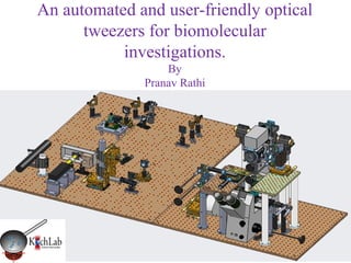
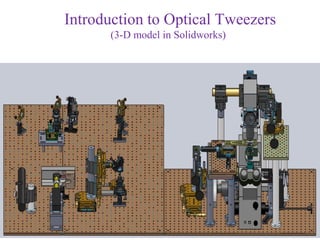
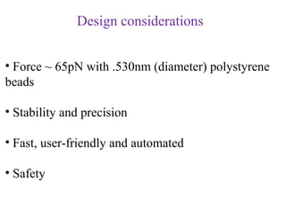
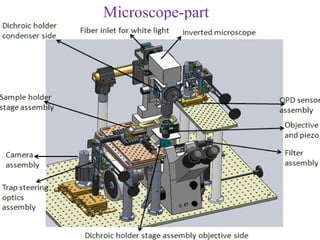
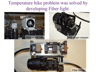
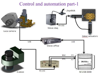
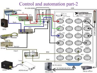
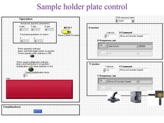
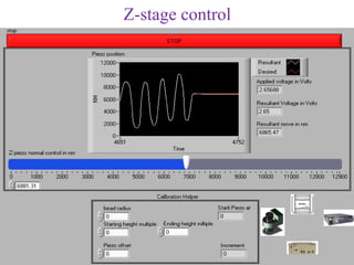
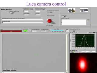
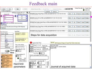
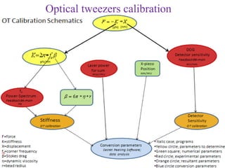
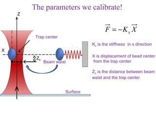
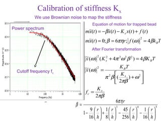
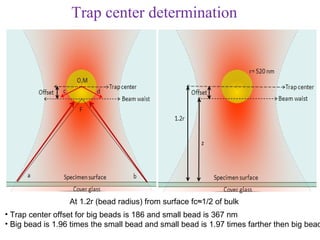
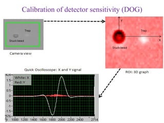
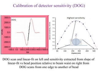
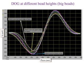
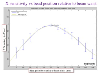
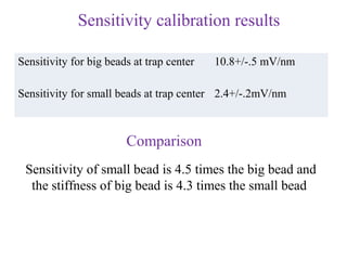
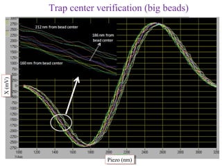
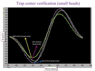
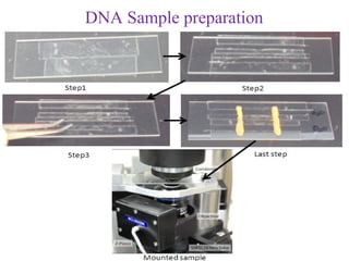
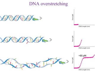
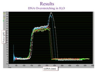
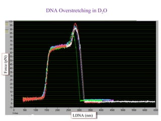
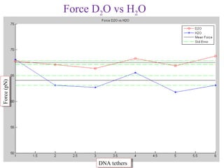
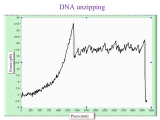
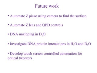
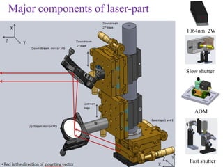
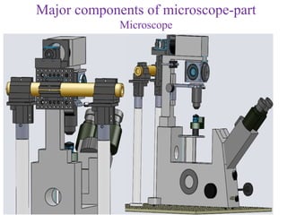
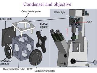
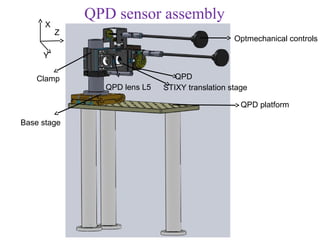
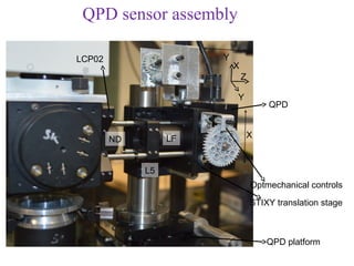
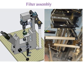
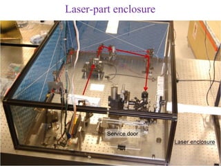
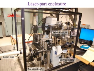
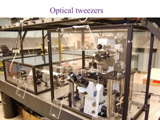
An automated and user-friendly optical
      tweezers for biomolecular
           investigations.
                  By
              Pranav Rathi
Acknowledgments


               Dr. Larry Herskowitz                         Dr. Andy Maloney


               Dr. Anthony Salvagno
                                                              Dr. Steven Koch


 Collaborations

 Susan Atlas—Lead of the DTRA project
 UNM Physics / Cancer Center / Director of CARC

 Haiqing Liu (G. Mantano lab)—Microdevice applications of kinesin
 LANL & Center for Integrated Nanotechnology (CINT)


Funding    DTRA—DTRA CB Basic Research Program under Grant No. HDTRA1-09-1-008
Outline


• Introduction to optical tweezers
• Design and construction
• Automation and control
• Optical tweezers calibration
• DNA sample preparation
• Results
Introduction to Optical Tweezers
      (3-D model in Solidworks)
Optical Tweezers are used to apply forces over nanometer scale on the
                        order of piconewtons


                     F= ∆p
                                 ∆t


                            P
                     F = Qn
                            c


                    F= F +F s
                             2
                                      g
                                       2
Model to explain optical trap


                                 λ≈d


Electric dipole model   Electromagnetic field model   Ray optics model
Design considerations


• Force ~ 65pN with .530nm (diameter) polystyrene
beads

• Stability and precision

• Fast, user-friendly and automated

• Safety
Optical path
Design
Laser-part
Microscope-part
Some problems with the design!


• Accessibility to optomechanical controls of Z lens,
 QPD and microscope

• Temperature hike inside enclosure

• Mechanical vibration nose
Accessibility problem was solved by extending
           optomechanical controls


        Z-lens controls                       QPD controls


                            Microscope focus control
Temperature (C)
Temperature (C)
                  Temperature hike problem


                            Seconds (S)
                             Seconds (S)
Temperature hike problem was solved by
        developing Fiber light


        Microscope inlet    Fiber plugin adapter


                                Fiber feeder
Mechanical vibration noise


Mechanical noise               Airborne noise
Control and automation part-1
Control and automation part-2
Sample holder plate control
Z-stage control
Luca camera control
Video section


  Live-feed section
Feedback main


             Steps for data acquisition


Hard limit
parameters                       Journal of acquired data
Optical tweezers calibration
The parameters we calibrate!
    Z


                                        F = −Kx X
         Trap center
                                 Kx is the stiffness in x direction
X
         Zb                      X is displacement of bead center
              Beam waist         from the trap center

                                 Zb is the distance between beam
                                 waist and the trap center.


                       Surface
Calibration of stiffness Kx
           We use Brownian noise to map the stiffness
                                         Equation of motion for trapped bead
Power spectrum
                                   m(t ) = − β x(t ) − K x x(t ) + f (t )
                                    x            
                                                                        2
                                   m(t ) = 0; β = 6πηr ; f (ω ) = 4 β k BT
                                    x
                                         After Fourier transformation
                                    ~ (ω) 2 ( K 2 + 4π 2ω 2 β 2 ) = 4 βK T
                                    x           x                       B

                                    ~ (ω) 2 =           K BT
  Cutoff frequency fc               x
                                                       K          
                                                π 2 β ( x ) + ω 2 
                                                       2πβ        
                                          Kx
                                    fc =
                                         2πβ
                                                      6πη r
                              β=                      3             4         5
                                         9  r  1  r  45  r  1  r 
                                   1−       +   −          −  
                                        16  h  8  h  256  h  16  h 
Trap center determination


                  At 1.2r (bead radius) from surface fc≈1/2 of bulk
• Trap center offset for big beads is 186 and small bead is 367 nm
• Big bead is 1.96 times the small bead and small bead is 1.97 times farther then big bead
Corner frequency vs bead center height from surface (H2O)
Corner frequency (Hz)


                        Bead center height (multiples of r=520 nm from surface)
                        Bead center height (multiples of r=520 nm from surface)
Corner frequency vs bead center height from surface
                                           H2O vs D2O
Corner frequency (Hz)


                             Bead center height (multiples of r=265 nm from surface)
                             Bead center height (multiples of r=265 nm from surface)
Stiffness vs bead center height from surface
                                                 H2O vs D2O
Perceived stiffness (pN/nm/W)


                                   Bead center height (multiples of r=520 nm from surface)
                                   Bead center height (multiples of r=520 nm from surface)
                                Stiffness does not depend on height but corner frequency does
Stiffness calibration results
         Big beads (1.04µm; diameter)
Estimated stiffness (H2O)   .038(7) pN/nm
Average variance (H2O)      12300+/-800 mV2

Estimated stiffness (D2O)   .04(2) pN/nm
Average variance (D2O)      12500+/800 mV2

       Small beads (.530µm; diameter)
Estimated stiffness (H2O)   .011(5) pN/nm
Average variance (H2O)      2100+/-200 mV2

Estimated stiffness (D2O)   .012(5) pN/nm
Average variance (D2O)      2000+/-300 mV2
Calibration of detector sensitivity (DOG)


DOG scan and linear-fit on left and sensitivity extracted from slope of
  linear-fit vs bead position relative to beam waist on right from
            DOG scans from one edge to another of bead
X (mV)
X (mV)   DOG at different bead heights (big beads)


                            Piezo (nm)
                             Piezo (nm)
X sensitivity vs bead position relative to beam waist
X Sensitivity (mV/nm)


                                                                         Big beads

                             Bead position relative to beam waist (nm)
                             Bead position relative to beam waist (nm)
Sensitivity calibration results

Sensitivity for big beads at trap center   10.8+/-.5 mV/nm

Sensitivity for small beads at trap center 2.4+/-.2mV/nm


                        Comparison
 Sensitivity of small bead is 4.5 times the big bead and
  the stiffness of big bead is 4.3 times the small bead
X (mV)
X (mV)   Trap center verification (big beads)


                        Piezo (nm)
                         Piezo (nm)
X (mV)
X (mV)   Trap center verification (small beads)


                          Piezo (nm)
                           Piezo (nm)
DNA Sample preparation
DNA overstretching


                     ~65 pN
Results
             DNA Overstretching in H2O
Force (pN)
Force (pN)


                       LDNA (nm)
                        LDNA (nm)
DNA Overstretching in D2O
Force (pN)
Force (pN)


                       LDNA (nm)
                        LDNA (nm)
Force (pN)
Force (pN)
             Force D2O vs H2O


                   DNA tethers
                   DNA tethers
Force (pN)
             DNA unzipping
Force (pN)


                Piezo (nm)
                 Piezo (nm)
Future work
• Automate Z piezo using camera to find the surface

• Automate Z lens and QPD controls

• DNA unzipping in D2O

• Investigate DNA protein interactions in H2O and D2O

• Develop touch screen controlled automation for
optical tweezers
Thank You
Appendix: A
Major components of laser-part
                                 1064nm 2W


                                 Slow shutter


                                    AOM


                                  Fast shutter
Major components of microscope-part
             Microscope
Luca Camera
                       X
                           Z

                           Y


460A-XY stage


    Base stage 1 & 2
Trap steering optics and dichroic holder stage assembly

                                             Dichroic holder stage


Trap steering lens
Dichroic holder stage assembly
         Mirror holder
Lens tube
holder


          L4                                             Top view
                      Holder stage
          Clip

                    Dichroic holder stage
 X        Z         platform
                                            Z
      Y
Before reflection                     X         Y
                                      After reflection
Different parts of dichroic holder stage assembly


                                       Slot


                  Clamp
                                      Clip

                            Slot
Sample holder stage assembly
                      Sample holder plate


              X-piezo stage

              Adapter plate
              X-Y translation stage


              6x4 inches bread board

            Sample holder stage platform
Sample holder plate


Rubber cushion


                 Lower side


                              Sample side

                 Upper side
Condenser and objective


                  Condenser


                   Objective


Z-Piezo
                 SM1L10 lens tube
Condenser and objective
                 Cube holder plate             White light

LB6C plate
                                                             QPD
                                  LCP02
                                  adapter


SM2D25D
aperture

  Dichroic holder cube LC6W
                              LB4C mirror holder
QPD sensor assembly
      X
          Z
                                                 Optmechanical controls

     Y

    Clamp                        QPD
                QPD lens L5   STIXY translation stage

                                                   QPD platform

Base stage
QPD sensor assembly

LCP02                  Y
                           X
                               Z

                           Y
                                       QPD


                  LF               X
        ND


             L5
                                   Optmechanical controls
                                   STIXY translation stage


                                       QPD platform
Filter assembly
Laser-part enclosure


         Service door
Laser-part enclosure


                            Service door1


Beam pipe
                                  Service door2


            Service door3
Optical tweezers

An automated and user-friendly optical tweezers for biomolecular investigations (PhD Defense)

  • 1.
    An automated anduser-friendly optical tweezers for biomolecular investigations. By Pranav Rathi
  • 2.
    Acknowledgments Dr. Larry Herskowitz Dr. Andy Maloney Dr. Anthony Salvagno Dr. Steven Koch Collaborations Susan Atlas—Lead of the DTRA project UNM Physics / Cancer Center / Director of CARC Haiqing Liu (G. Mantano lab)—Microdevice applications of kinesin LANL & Center for Integrated Nanotechnology (CINT) Funding DTRA—DTRA CB Basic Research Program under Grant No. HDTRA1-09-1-008
  • 3.
    Outline • Introduction tooptical tweezers • Design and construction • Automation and control • Optical tweezers calibration • DNA sample preparation • Results
  • 4.
    Introduction to OpticalTweezers (3-D model in Solidworks)
  • 5.
    Optical Tweezers areused to apply forces over nanometer scale on the order of piconewtons F= ∆p ∆t P F = Qn c F= F +F s 2 g 2
  • 6.
    Model to explainoptical trap λ≈d Electric dipole model Electromagnetic field model Ray optics model
  • 7.
    Design considerations • Force~ 65pN with .530nm (diameter) polystyrene beads • Stability and precision • Fast, user-friendly and automated • Safety
  • 8.
  • 9.
  • 10.
  • 11.
  • 12.
    Some problems withthe design! • Accessibility to optomechanical controls of Z lens, QPD and microscope • Temperature hike inside enclosure • Mechanical vibration nose
  • 13.
    Accessibility problem wassolved by extending optomechanical controls Z-lens controls QPD controls Microscope focus control
  • 14.
    Temperature (C) Temperature (C) Temperature hike problem Seconds (S) Seconds (S)
  • 15.
    Temperature hike problemwas solved by developing Fiber light Microscope inlet Fiber plugin adapter Fiber feeder
  • 16.
  • 17.
  • 18.
  • 19.
  • 20.
  • 21.
    Luca camera control Videosection Live-feed section
  • 22.
    Feedback main Steps for data acquisition Hard limit parameters Journal of acquired data
  • 23.
  • 24.
    The parameters wecalibrate! Z F = −Kx X Trap center Kx is the stiffness in x direction X Zb X is displacement of bead center Beam waist from the trap center Zb is the distance between beam waist and the trap center. Surface
  • 25.
    Calibration of stiffnessKx We use Brownian noise to map the stiffness Equation of motion for trapped bead Power spectrum m(t ) = − β x(t ) − K x x(t ) + f (t ) x  2 m(t ) = 0; β = 6πηr ; f (ω ) = 4 β k BT x After Fourier transformation ~ (ω) 2 ( K 2 + 4π 2ω 2 β 2 ) = 4 βK T x x B ~ (ω) 2 = K BT Cutoff frequency fc x  K  π 2 β ( x ) + ω 2   2πβ  Kx fc = 2πβ 6πη r β= 3 4 5 9  r  1  r  45  r  1  r  1−  +   −   −   16  h  8  h  256  h  16  h 
  • 26.
    Trap center determination At 1.2r (bead radius) from surface fc≈1/2 of bulk • Trap center offset for big beads is 186 and small bead is 367 nm • Big bead is 1.96 times the small bead and small bead is 1.97 times farther then big bead
  • 27.
    Corner frequency vsbead center height from surface (H2O) Corner frequency (Hz) Corner frequency (Hz) Bead center height (multiples of r=520 nm from surface) Bead center height (multiples of r=520 nm from surface)
  • 28.
    Corner frequency vsbead center height from surface H2O vs D2O Corner frequency (Hz) Corner frequency (Hz) Bead center height (multiples of r=265 nm from surface) Bead center height (multiples of r=265 nm from surface)
  • 29.
    Stiffness vs beadcenter height from surface H2O vs D2O Perceived stiffness (pN/nm/W) Perceived stiffness (pN/nm/W) Bead center height (multiples of r=520 nm from surface) Bead center height (multiples of r=520 nm from surface) Stiffness does not depend on height but corner frequency does
  • 30.
    Stiffness calibration results Big beads (1.04µm; diameter) Estimated stiffness (H2O) .038(7) pN/nm Average variance (H2O) 12300+/-800 mV2 Estimated stiffness (D2O) .04(2) pN/nm Average variance (D2O) 12500+/800 mV2 Small beads (.530µm; diameter) Estimated stiffness (H2O) .011(5) pN/nm Average variance (H2O) 2100+/-200 mV2 Estimated stiffness (D2O) .012(5) pN/nm Average variance (D2O) 2000+/-300 mV2
  • 31.
    Calibration of detectorsensitivity (DOG)
  • 32.
    Calibration of detectorsensitivity (DOG) DOG scan and linear-fit on left and sensitivity extracted from slope of linear-fit vs bead position relative to beam waist on right from DOG scans from one edge to another of bead
  • 33.
    X (mV) X (mV) DOG at different bead heights (big beads) Piezo (nm) Piezo (nm)
  • 34.
    X sensitivity vsbead position relative to beam waist X Sensitivity (mV/nm) X Sensitivity (mV/nm) Big beads Bead position relative to beam waist (nm) Bead position relative to beam waist (nm)
  • 35.
    Sensitivity calibration results Sensitivityfor big beads at trap center 10.8+/-.5 mV/nm Sensitivity for small beads at trap center 2.4+/-.2mV/nm Comparison Sensitivity of small bead is 4.5 times the big bead and the stiffness of big bead is 4.3 times the small bead
  • 36.
    X (mV) X (mV) Trap center verification (big beads) Piezo (nm) Piezo (nm)
  • 37.
    X (mV) X (mV) Trap center verification (small beads) Piezo (nm) Piezo (nm)
  • 38.
  • 39.
  • 40.
    Results DNA Overstretching in H2O Force (pN) Force (pN) LDNA (nm) LDNA (nm)
  • 41.
    DNA Overstretching inD2O Force (pN) Force (pN) LDNA (nm) LDNA (nm)
  • 42.
    Force (pN) Force (pN) Force D2O vs H2O DNA tethers DNA tethers
  • 43.
    Force (pN) DNA unzipping Force (pN) Piezo (nm) Piezo (nm)
  • 44.
    Future work • AutomateZ piezo using camera to find the surface • Automate Z lens and QPD controls • DNA unzipping in D2O • Investigate DNA protein interactions in H2O and D2O • Develop touch screen controlled automation for optical tweezers
  • 45.
  • 46.
  • 48.
    Major components oflaser-part 1064nm 2W Slow shutter AOM Fast shutter
  • 49.
    Major components ofmicroscope-part Microscope
  • 50.
    Luca Camera X Z Y 460A-XY stage Base stage 1 & 2
  • 51.
    Trap steering opticsand dichroic holder stage assembly Dichroic holder stage Trap steering lens
  • 52.
    Dichroic holder stageassembly Mirror holder Lens tube holder L4 Top view Holder stage Clip Dichroic holder stage X Z platform Z Y Before reflection X Y After reflection
  • 53.
    Different parts ofdichroic holder stage assembly Slot Clamp Clip Slot
  • 54.
    Sample holder stageassembly Sample holder plate X-piezo stage Adapter plate X-Y translation stage 6x4 inches bread board Sample holder stage platform
  • 55.
    Sample holder plate Rubbercushion Lower side Sample side Upper side
  • 56.
    Condenser and objective Condenser Objective Z-Piezo SM1L10 lens tube
  • 57.
    Condenser and objective Cube holder plate White light LB6C plate QPD LCP02 adapter SM2D25D aperture Dichroic holder cube LC6W LB4C mirror holder
  • 58.
    QPD sensor assembly X Z Optmechanical controls Y Clamp QPD QPD lens L5 STIXY translation stage QPD platform Base stage
  • 59.
    QPD sensor assembly LCP02 Y X Z Y QPD LF X ND L5 Optmechanical controls STIXY translation stage QPD platform
  • 60.
  • 61.
  • 62.
    Laser-part enclosure Service door1 Beam pipe Service door2 Service door3
  • 63.