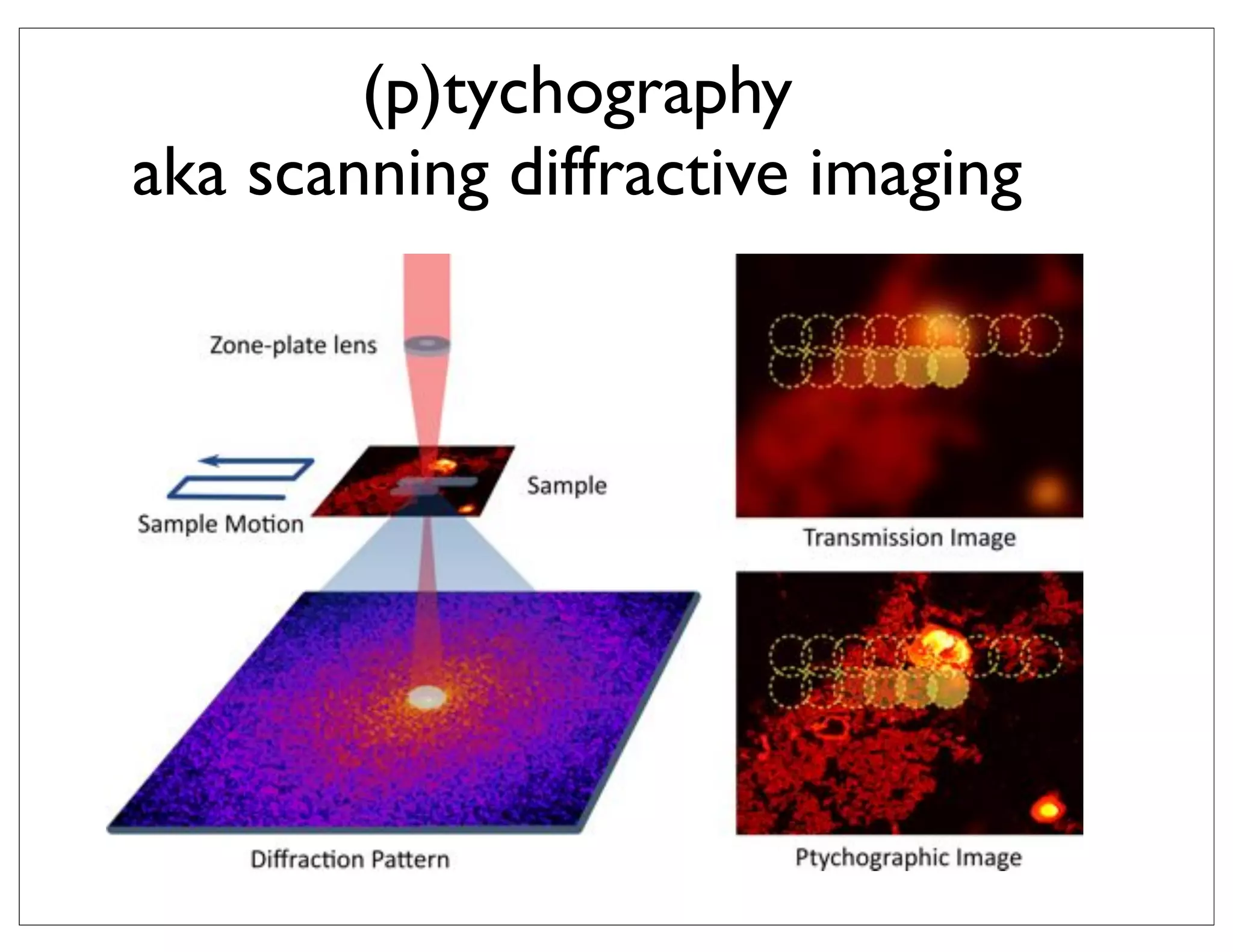
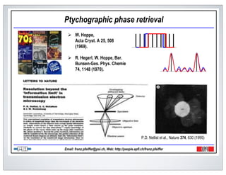
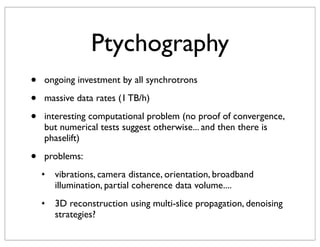
Ptychography is a technique for scanning diffractive imaging that allows reconstruction of the phase and amplitude of an object from multiple diffraction patterns collected at different positions. It uses an iterative algorithm to recover the object by alternating between updating an estimated object and simulated diffraction patterns. This document discusses using ptychography at scanning transmission x-ray microscopes to achieve resolutions below 10 nm, as well as its applications in 3D imaging of biological samples with resolutions of 100nm or better and quantitative chemical analysis.

![. m n
. = i
|ai | 2 i x2
z1 d
ptychography (5.3.2.1 STXM-ALS)
r2 x1
m×m r2
m n
r q1 1 r1
R. Celestre, A D. Kilcoyne, Tolek T, A. Schirotzek, T. Warwick(ALS),
microscopy ptychography SEM
70 nm probe
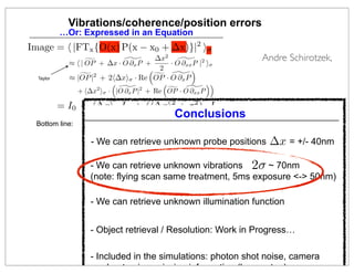
Figure 1: Forward ptychographic problem: diffraction data ai is related to the unkown object
ˆ
to reconstruct ψ by a = |FQψ|. The intermediate variable zi describing individual frames is
used in many iterative methods [?].
In the following, we concatenate indices q and i of ai (q) and express
a1 Q1 F z1
ˆ
. . .
a = . , Q = . , F =
. .
..
. , z = . , k = κ
ˆ .
2
(3)
ak Qk F zk
ˆ
and rewrite (Eq. 1) as
|F z| = a,
ˆ (4)
ˆ ˆ
z = Qψ, (5)
referred to as a Fourier magnitude problem and an overlapping illumination problem. The
ptychographic reconstruction problem Maia GPU/MPI knowing a, Q. Many iterative
F. consists in finding ψ ˆ 5.3.2.1
1 micron reconstruction
methods introduce an intermediate variable z, and attempt to solve the two problems in Eqs.
(??) using projection algorithms, iterative transform methods, or alternating direction methods
E=1keV
[?].
15 nm resolution
In the following section we will describe the standard operators commonly used in the
literature. In section 3 we will introduce an intermediate variable ci , replacing Eq. (5) with
700 ms exposure
ci zi = Qi ψ, i = (1, . . . , k). This intermediate variable allows us to fix perturbations in the
incident flux and increase rate of convergence for large scale problems.
longer exposure
2
should give 7 nm res](https://image.slidesharecdn.com/ucb-math4small-120228152420-phpapp02/85/UCB-2012-02-28-2-320.jpg)
![men PHASE-RETRIEVAL X-RAY MICROSCOPY BY WIGNER-DISTRIBUTION
with complex transmission ψ(r) is situated in the focal plane and
in that plane. At DECONVOLUTION:scan the sample is displaced
a given point in the SIGNAL PROCESSING
e optical axis by a vector −x.Microscopy Stony 1997 (Pages 67-80) sample
Scanning (On the Vol. 11, Brook STXM the
ly scanned in the negative directions, International, ChicagoWignermotion IL 60666 USA
Scanning Microscopy soN. Chapman apparent O’Hare), of x-ray microscopy
that the
pixel sample is in the positive directions.) The x-ray deconvolution
be across the translation
Henry (AMF
wavefield
Fourier transform
ately behind the specimen will then SUNY at Stony a(r)ψ(r + x), and the
Department of Physics, be given by Brook, Stony Brook, NY
illuminationPHASE-RETRIEVAL X-RAY MICROSCOPY BY WIGNER-
y at the far-field microdiffraction object be written as [1]
plane can
intensity
DECONVOLUTION: SIGNAL PROCESSIN
2
m(r , x) Abstract
= A(r
− x )Ψ(x ) exp(2πix
· x) dx . (1)
Introduction
Henry N. Chapman
Phase and amplitude images have been Wigner-deconvolution phase-retrieval microscop
structed from data collected in a scanning Department of Physics, retrievingStony Brook, Stony Brook
is a new technique for SUNY at the phase and amplitude o
mission x-ray microscope by applying the method of referred to in microscope images (Rodenburg and Bates
ensity m(r , x) for constant x (further transmission this paper as
lane of m)deconvolution. This required collecting pattern, recordedRodenburg, 1989). This technique can b
r-distribution is a single microdiffraction 1992; Bates and as a single
ent microdiffraction patterns (1) shows thattwo- microdiffraction microscope of either the scanning o
f the CCD. Equation at each point of a the employed in a wavefield is
Abstract In
rier transform object and then deconvolving the of conventional geometry and allows the formation o
sional scan of an of the complex transmission the specimen, multiplied
imensional Wigner-distribution function of the lens superresolved images (Rodenburg and Bates, 1992; Nellis
asedata set. and processconvolvedanalyses the pupil function. This1994). The phase-retrieval an
the
ramp, The then essentially with the
Phase and amplitude images have equation
and Rodenburg, been Wigner-deconvo
much about the imaging processplane anddata collected in a characteristics ofis a new technique for re
rence which occurs in the microdiffraction and the role of the microdiffraction the technique have bee
reconstructed from superresolution scanning
the object transmission transmission grating, which has of transmission microscopes tha
scanned. x-ray microscopedemonstratedthe method a dis- transmission microscop
Consider aasspecimen,issuch as a The image-
modulates by applying in scanning
ssing steps required to deconvolve experimental deconvolution. This required collecting
Wigner-distribution 1992; Bates and Rodenb
ourier transform consisting of severaldata patterns atorders. light a incident employed in a micros
diffraction each point of (McCallum and Rodenburg, 1992)
utilise visible The
coherent microdiffraction
scribed. These steps result in the reconstructions of two-
electrons (Rodenburg et al., 1993; Nellist et al., 1995), an
ent beam is diffracted by the object so object and then deconvolving the of conventional geometr
dimensional scan of an that soft x-rays (Chapman, order In a scanning microscope th
each diffraction
tion-limited phased images, to a spatial-frequency cut-
1996).
cimen -1. The estimated accuracy)] yields Wigner-distribution function ofcollecting a two-dimensional micro
1/45 nm [each non-zero four-dimensional a pupil function A(r ) in the mi- superresolved images (R
Ψ(x of the images is method requires the lens
action plane, centred fromData data set. The = x and multiplied by convergent beam diffractio
ad in phase and 10% in amplitude. the frequency r process essentially analyses the the and Rodenburg, 199
at the were collected diffraction pattern (a coherent
-ray wavelength of 3.1 nm. interference which occurs in the microdiffraction plane a two-dimensional scan. The abilit
pattern) at each point in and superresolution characte](https://image.slidesharecdn.com/ucb-math4small-120228152420-phpapp02/85/UCB-2012-02-28-7-320.jpg)
![= F (r )F (r − x ) exp(2πir · r ) dr . (5)
F (rwith (r − x ) transmission ψ(r)
)F ∗ complex exp(2πir · r ) MICROSCOPY the focal plane and
men PHASE-RETRIEVAL X-RAYdr . is situated inBY WIGNER-DISTRIBUTION (5)
r inx) is plane. At DECONVOLUTION:scan the sample is displaced of the
, that actually a given point in the SIGNAL PROCESSING WDF
a four-dimensional convolution of the
bution withby a vector −x.Microscopy Stony 1997 (Pages 67-80)the sample object.
eactuallyaxis the WDF of(On the Vol. 11, Brook STXMthe of the
optical a four-dimensional convolution of the WDF of
Scanning the complex transmission
with of thisthe negative directions, International, ChicagoWignermotion IL 60666 USA
ly scanned in of the complex transmissionthe apparent O’Hare), of x-ray microscopy
Scanning Microscopy soN. Chapman deconvolution.
namethe WDFmethod, Wigner-distributionthe object. that of
pixel sample is in the positivedeconvolution. x-ray deconvolution
f this method, translation
Henry
be across the Wigner-distribution directions.) The
(AMF
wavefield
illumination object Fourier transform decon-
ately behind the specimen will then SUNY at Stony a(r)ψ(r + x), and the
Department of Physics, be given by Brook, Stony Brook, NY
WDF, Wa , contains zerosPHASE-RETRIEVAL X-RAY MICROSCOPY BY WIGNER-
y a , contains zeros and regionsand regions of low decon-
W plane intensity, the intensity, the
at the far-field microdiffractionof low can be written as [1]
best performed usingfilter. That is, an estimate, Wan of intensity˜ψ , of
That is, ˜ψ , estimate, W
rformed using a Wiener a Wiener filter. DECONVOLUTION: SIGNAL PROCESSIN
2
f them(r specimen is − x )Ψ(x ) exp(2πix · x) dx .
given by given by
pecimen is, x) Abstract
= A(r
(1)
Introduction
Henry N. Chapman
Phase and amplitude images a (r, −x ) W ∗ (r, −x )
W ∗ have been
W a linear problem
˜ψ (r, x )˜= M(r, x )
illumination
Wigner-deconvolution phase-retrieval microscop
, is a new technique(6)SUNY at the phase and amplitude o
collected in a scanning a Department of Physics, retrievingStony Brook, Stony Brook
structed Wψ (r, x ) = M(r, x ) 2
referred 2 in , (6)
from data
)| + φ for
|Wa (r, −x
ensityx-ray microscope by applying the method (r, −x )|to+ φthis paper as (Rodenburg and Bates
m(r , x) for constant x (further a transmission microscope images
mission −1 −1
|Wof
a a
a = microdiffraction m(r , x)] = and Rodenburg,1989). (r, x )
lane of m)deconvolution.F required collecting pattern, recordeda (r,a single ψThis technique can b
isx) single This
M(r,An estimate →r the specimen transmission can −x )W 1992; Bates W as
r of Fx→x
r-distribution
ent constant. Equation (1) shows thattwo- microdiffraction microscope of either the scanning o
ll the CCD.
f amicrodiffraction patterns atAn estimate of the specimen transmission can
small constant. then deconvolving theAbstract
each point of a employed in a wavefield is
rier transform object and FT FT Data
by first Fourier transforming transmission of conventional geometry and allows the formation In
sional scan of an of the complex the WDF to give specimen, multiplied
the the
unknown
o
tained byand then convolved with the pupilsuperresolved Thisgive
ramp, first Fourier Phase and amplitude images have 1994). The phase-retrieval an
transforming the WDF imagesequation and Bates, 1992; Nellis
imensional Wigner-distribution function of the lens
asedata set. The process essentially analyses the function. to been
(Rodenburg
˜ψ ˜ ˜
the, x ) = F {W (r, x )} = Ψ(r )Ψ∗ (r − x and Rodenburg, Wigner-deconvo
r r ), of the in a scanning
(7)
rence which occurs in the microdiffraction and the role
reconstructed from
Consider aas,the object Frscanned. a The )} =
W
modulates x ) = {W ˜ superresolution scanning
˜∗
by Ψ (r in x ),
x-ray microscopedemonstrated −method a dis- Wigner
much about the imaging processplane anddata collected microdiffraction is a new technique for re
˜ψ (r specimen,issuch ˜ψ (r, ximage- Ψ(r )applying thecharacteristics oftransmission microscop
the technique have bee
(7)
transmission transmission grating, which has of transmission microscopes tha
as
WDF to give the specimen’s transform as utilise visible follows:
ssing steps required to deconvolve experimental deconvolution. This required collecting
Wigner-distribution distribution
1992; Bates and Rodenb
ourier transform consisting of severaldata patterns atorders. light a incident employed in a micros
diffraction each point of (McCallum and Rodenburg, 1992)
coherent microdiffraction
The two-
ing beamWDF ∗to give the˜specimen’s electrons (Rodenburgfollows:conventional 1995), an
ent the is diffracted by the object so object transform as etthe 1993; Nellist et al., geometr
scribed. These steps result in the reconstructions of
that and then deconvolving al., of
each diffraction order function
1/45 nm
˜
Ψ(x ) = Wψ dimensional scan of an
tion-limited phased ˜ (0, −xspatial-frequency cut-
images, to a )/ Wψ (0, 0). solution (8)
soft x-rays (Chapman, 1996). In a scanning microscope th
cimen -1. The estimated accuracy)] yields Wigner-distribution function ofcollecting a two-dimensional micro
[each non-zero four-dimensional a pupil function A(r ) in the mi- superresolved images (R
Ψ(x of the images is method requires the lens
action plane, centred fromData data set. The =˜x and multiplied by convergent beam diffractio
ad in phase and 10% in amplitude. the∗ frequency r process essentially analyses the the and Rodenburg, 199
the
at ˜ were collected
˜ found by inverse Fourier thediffraction patternplane and
Ψ(x ) interference which occurs Wψmicrodiffraction (a in
-ray wavelength of 3.1 (0, 0).each point coherent superresolution characte
ct, ψ(x), is then nm. = Wψ (0, −x )/ in transformation of a two-dimensional scan. The abilit
˜
pattern) at
(8)](https://image.slidesharecdn.com/ucb-math4small-120228152420-phpapp02/85/UCB-2012-02-28-8-320.jpg)
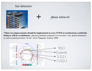
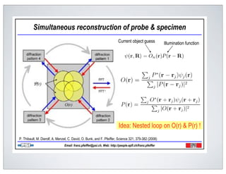
![WIGNER DISTRIBUTION FUNCTION
ψ(r) wavefield
Wigner distribution function
Wψ (r, dr) = ψ(r + dr/2)ψ(r − dr/2)
phase space
Wψ (r, q) = [Fdr→q ] ψ(r + dr/2)ψ(r − dr/2) quasi probability distribution
lifting cyclic permutation
note: ψ ψ rank 1 ψ(r + dr/2)ψ(r − dr/2)](https://image.slidesharecdn.com/ucb-math4small-120228152420-phpapp02/85/UCB-2012-02-28-9-320.jpg)
![WIGNER DISTRIBUTION FUNCTION
ψ(r) wavefield
Wψ (r, dr) = ψ(r + dr/2)ψ(r − dr/2)
phase space
Wψ (r, q) = [Fdr→q ] ψ(r + dr/2)ψ(r − dr/2) quasi probability distribution
lifting cyclic permutation
note: ψ ψ rank 1 ψ(r + dr/2)ψ(r − dr/2)
phase space description of light
light source phase space 2π
q= λ θ
r propagation
q
ψ(r)
r
θ direction](https://image.slidesharecdn.com/ucb-math4small-120228152420-phpapp02/85/UCB-2012-02-28-10-320.jpg)
![on m×m illuminates an unknown object of interest ψ(r+x). For simplicity we conside
ill summarizeusedptychographic problem following the notation of Yang et al.
the in many iterative methods [?].
hography experiment, a two dimensional small beam with distribution w(r)also be considered. One collect
matrices, generalization to non-square matrices can of
ˆ
PROJECTION ALGORITHMS
nce of k diffraction images a2 (q) of dimension m × m
×m illuminates an unknown object of interest ψ(r+x). For simplicity we consideras the position x of the objec
to non-square matricesx
es, generalization In the following, we introduce be sequences of various matrices as follows
can also k considered. One collects
red. Eachimages ax a of dimension m the the position xof the discrete two dimensional Fourie
k diffraction frame 2 (q)x represents× m asmagnitude of the object
m Fˆ of w(r)ψ(r ˆ the magnitude
ach frame ax represents + x): a1 of the discrete1 two dimensional Fourier
Q z1
ˆ F
illumination
f w(r)ψ(r + x): unknown
. . . ..
a = . , Q = . , z = . , F =
. . ˆ . . (2)
ˆ z = 2π(1)
ax (q) =axFw(r)ψ(r + x)Fw(r)rm, q + 2π m , Qkr = rm, qˆk
(q) ˆ= , r =aψ(r = x) r m (1
k r
F
Ff =
diffraction edata
eiq·r f (r), m = as a = |F Qψ|,(0 . .using 1), intermediate variable z as:
and rewrite (Eq. iq·r(µ, ν) , µ, ν ˆ or . m − the
Ff = f (r), 1) =
feasibility problem ˆ
m = (µ, ν) , µ, ν = (0 . . . m − 1),
r
probe translate
gthscale, and the sum over r is given on all the indices m × m = r. z|,
r a of |F ˆ Fourier magnitude (3)
stered around, r + x spans a grid of dimension n × n, n m. We denote Qx
ˆ
“illumination matrix” that frames ˆ
s a lengthscale, andextracts a frame containinggiven = Qψ, thean
z Split into frames
the sum over r is m × m on all of indices m × m of r.
pixels out
(4)
ining rastered andto as Fourier magnitude grid of dimension n × illumination We denote
x is n × n pixels, around,a r + x spans a illuminationand an overlapping n, n m.problem respec- Q
referred multiplies the frame by the problem function w(r):
ˆ + x) Qx (r)ψ matrix” (r) = extracts
ˆ ˆ a F ˆ Q
m2 × w(r)ψ(rtively.= The ptychographic xreconstruction. problem consists in findingm × m pixels out of a
n2 “illumination = zx (r), Q that w(r)eix∂r a frame containing ψ knowing a,ψQ. Many
( )( )( )( )
ˆ
ψ containing n × methodsindividual multiplies thevariable z, and attempt to solve thefunction w(r)
iterative n pixels, introduce an intermediate
intermediate variable describing w and frames that we a1 frame convi-
introduce for by the illumination
two problems
ψˆ
in Eqs. (??) using projection algorithms, iterative transform methods, or w Q
alternating direction
w
a2
F wQ
1
methods [?].
w(r)ψ(r F
ˆ + x) = Qx (r)ψ = zx (r), Qx (r) = w(r)eix∂r .
zi ˆ ˆ
2 ψ
Inw the F
the following section we will describe = standard operators commonly used in the
xi 1 m F
literature. In section 3 we will introduce an intermediate variable ci , replacing Eq. (4) with
is an intermediate ivariable, k). The linear projection operator Fthat we introduce for conv
ci zi = Qi ψ, = (1, . . . n
describing individual framescorresponding to the augmented
F
z
problem is computationally more intensive than for (Eq. 8), and speed may not always improve.
zk
.
.
.
=
However the benefits of introducing this augmented problem are the following:
|ai |2
• Intensity fluctuation introduced1 instabilities F the storage ring, optics etc, are given
z1 by in Q
by the coefficients cmand their effect can be removed (see Fig. 4).
m×i
• Accelerated convergence per iteration (Fig.2). A heuristic interpretation is that long
range phase fluctuations are poorly constrained by standard projection operators, result-
ing in degraded convergence rate for large scale problems. See also (Fig. 3) where the](https://image.slidesharecdn.com/ucb-math4small-120228152420-phpapp02/85/UCB-2012-02-28-12-320.jpg)
![arg min zi − zi , subject to |F z| = a,
¯ ψ ¯ (6)
¯
z
Q1 z1
ˆ F
mes. and zset .overlap=projection operator PQSimultaneous reconstruction of probe specimen
. norm. The . illuminations . .
ian of
. , ˆ = . , F
respectively. The (2) to enforce
running estimate
is used
PROJECTION ALGORITHMS
.
nsQQ:
btained by solving the least squares problem in Eq. (7):
zk
ˆ F
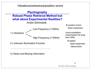
k Current object guess Illumination function
ψmin , using the (Q∗ Q)−1 Q∗ z. z − as: 2 ,
ψ|, or ψ where intermediate min
ˆ = ψmin = arg variable z Qψ
ˆ (7) (8)
min ψ
a = of |, Fourier magnitude
multiplies |F ˆilluminations respectively. The and merges all
ames and setby zthe conjugate of the probe w running estimate the
(3)
is the operator which splitsReduce frames Eq. and
ˆ
z = Qψ, ˆ (4)
obtained by solving the least squares problem frames (7): multiplies
an image into in
−1 is a normalization factor. The linear projection operator P
de problem and an overlapping illumination problem respec- Q Q*
()
∗ −1 ∗
ψproblem consists and solving (Eq. 13)Many (8) Q
min = (Q Q) in finding ψ knowing a, Q. is required when merging
Q z.
( )
olve independently, ˆ
)(
struction
W
ntermediate variable z, and−1 ∗ to solve the two problems
∗ attempt
at multiplies bytransform methods, or alternatingw and merges all the (9) Nested loop on O(r) P(r) !
Piterative the Q) Q , of the probe direction
orithms, Q = Q(Q conjugate Idea:
Q is the operator which splits an image intoP.frames and multipliesPfeiffer, Science 321, 379-382 (2008)
Thibault, M. Dierolf, A. Menzel, C. David, O. Bunk, and F.
Q)−1describe the standard factor. The the solutions the (7) and (6) are
lgorithm, approximation to linear of
split normalize merge
Email: franz.pfeiffer@psi.ch, Web: http://people.epfl.ch/franz.pfeiffer
will is a normalization operators commonly projection operator PQ
the used in
ction algorithms
ntroduce an intermediate variable ci , replacing Eq. (4) with
∗ −1 ∗
linear projection operator corresponding to the augmented
(+1)PQ = Q(Q Q) () , Q (9)
intensive P= for used ] and speed may not always frames
z [PQ PF z
Fourier amplitude
Alternating direction Methods for Classical and
jection thanthe (Eq. 8),to ensure the solutions of (7) satisfy measurements
algorithm, F is approximation to that the
improve. Ptychographic Phase Retrieval
this augmented problem are the following: Phase Retrieval and (6) are Wen , Chao Yang , Xin Liu , Stefano Marchesini
ing (+1) ∗ −1 ∗ (+1) ADM for
essed as: = (Q Q) Q z
ψ .
projection
1 2 3
Zaiwen
A test case: far-field phase retrieval with laser light
1 Department of Mathematics and Institute of Natural Sciences, Shanghai
Jiaotong University, Shanghai, 200240, CHINA
duced by instabilities in the storage ring, optics Algorithm given
etc, are Formula 2 Computational Research Division, Lawrence Berkeley National Laboratory,
Berkeley, CA 94720, USA
estimate =be ˆ Q ∗F ] Qψ. A number ofER
ˆ 3 Academy of Mathematics and Systems Science, Chinese Academy of Sciences,
effect [P ˆ = zz
heir z(+1)canof ψ, zP F(see Fig. 4).
removed () diffrent algorithms has Beijing 100080, CHINA
xk+1 = PS PM (xk )
serare(+1) F= = FA |F z| ∗·za. ∈ [0, 1] is is that long = (PS PM + I − PM ) (x ) (5) k
P z Tab. 1,
E-mail: zw2109@sjtu.edu.cn, cyang@lbl.gov and liuxin@lsec.cc.ac.cn
in (Q heuristic interpretation BIO
given(Fig.2). ∗ Q)−1with(+1) .
β xk+1
a relaxation parameter.
k
iteration
ψ Q HIO
Abstract. In this paper, we apply the widely used augmented Lagrangian
xk+1 = ((1 + β)PS PM + I − PS − βPM ) (x ).
alternating direction method (ADM) for solving both the classical and
Ptychographic phase retrieval problems. Although the sequence produced by
e poorly constrained by standard projection operators, result- = (1 + β)PS+ PM + I − PS+ − βPM (xk )
HPR xk+1
the hybrid input-output and hybrid projection algorithms can be generated from
these from the ADM method on the classical phase retrieval problem, they usually
perform quite differently in practice and the latter can often be much less sensitive
m ratetransform z problems. A PF is(Fig. 3) where xalgorithmsPhas βI that+ + (1 − 2β)PM (xk )
ng estimate of scale =updatingnumber of RAAR thein theS+sense − βPS
rier for large ψ, ˆ Qψ. See formula diffrent k+1 = 2βP M +
ce ˆ operator.
ˆ also a projection to the choice of the relaxation parameters. Similar behavior can also be observed
on Ptychographic phase retrieval problem. Moreover, the ADM method can
be competitive with the nonlinear conjugate gradient and Newton’s methods
z(+1) Tab. P with β ∈ PQ )(I a βPTable z() parameter.
on difficult instances in terms of both reconstruction quality and computational
les are given in = [PQ1, F + (I − [0, 1] is − relaxation list of projection algorithms for phase retrieval.
F )] 1. A
efficiency.
divide the problem inQ PF subject2β)PF z| = a, − I)]
z min zi − ¯ , + (1 − to |F ¯ and
= arg(+1) = [2βPzisubreconstruction regionsβ(PQreduce z()
+ 1. Introduction (6)
hm ¯
z updating formula Phase retrieval is a challenging inverse problem arising from a number of scientific](https://image.slidesharecdn.com/ucb-math4small-120228152420-phpapp02/85/UCB-2012-02-28-13-320.jpg)
![ROBUST RECONSTRUCTION TECHNIQUE
ptychography Diffractive imaging
0
RAAR ii=140
10
−2
10
−4
10
−6
10 |[Pf−I] x|
−8
|[Po−I] Pf x|
10
|Po x−xsol |
−10
10
0 100 200 300 400
iterations
reaches double precision](https://image.slidesharecdn.com/ucb-math4small-120228152420-phpapp02/85/UCB-2012-02-28-14-320.jpg)
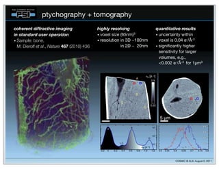
![POTENTIAL PROBLEMS
method CPU Matlab+GPU c++/cuda/mpi remarks
phase retrieval x x x x [arXiv:1105.5628]
probe retrieval x x x
beamstop no good x x regularization/high
solution yet pass filter?
recovered probe larger
detector binning x than field of view
intensity exact solution,
x x partial accelerated
fluctuations
convergence
works ok, we
position error fit/correct x know how to do
better
step size/ccd can someone compute
trial/error
distance gradient/matvec
works ok, in the fit
vibrations fit/deconvolve x partial vibrations are
averaged
incoherent only unknown
simulations
backtround offset
background numerical tests
needed
detector dynamic range is
noise more numerical
tests needed
x an issue, we can’t fix it by
x x
compressive... more numerical
tests needed numerical methods](https://image.slidesharecdn.com/ucb-math4small-120228152420-phpapp02/85/UCB-2012-02-28-15-320.jpg)


![[Download] rev chapter-5-june26th](https://cdn.slidesharecdn.com/ss_thumbnails/downloadrev-chapter-5-june26th-100803111359-phpapp01-thumbnail.jpg?width=640&height=640&fit=bounds)


![11.[23 36]quadrature radon transform for smoother tomographic reconstruction](https://cdn.slidesharecdn.com/ss_thumbnails/11-23-36quadratureradontransformforsmoothertomographicreconstruction-120512235621-phpapp01-thumbnail.jpg?width=640&height=640&fit=bounds)


