Download to read offline

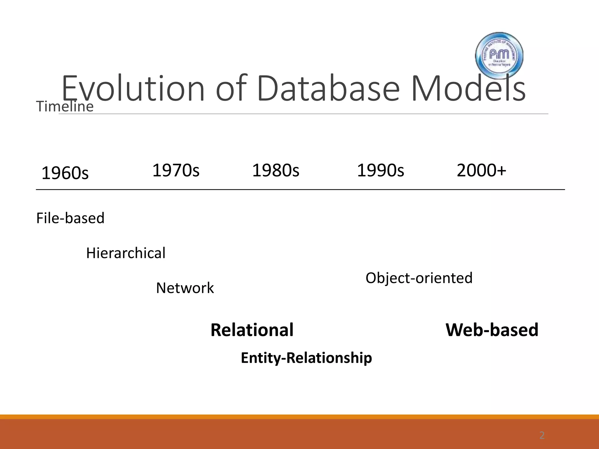
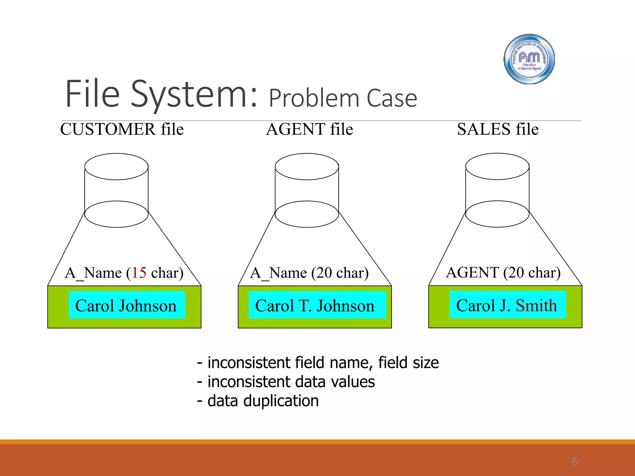
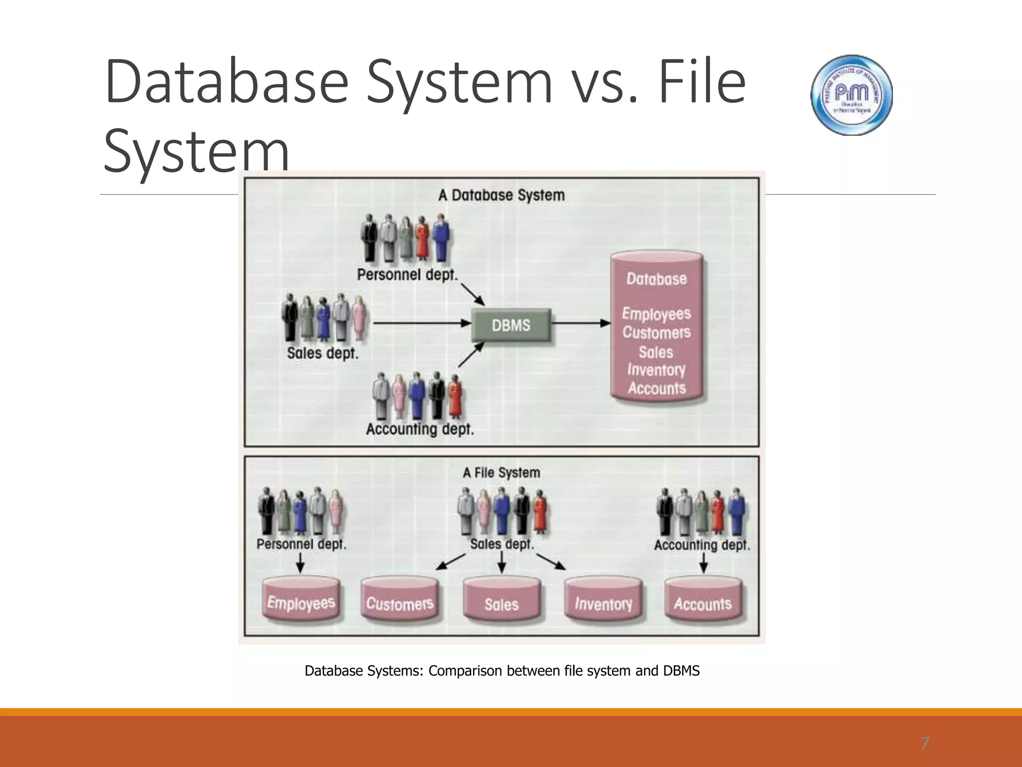
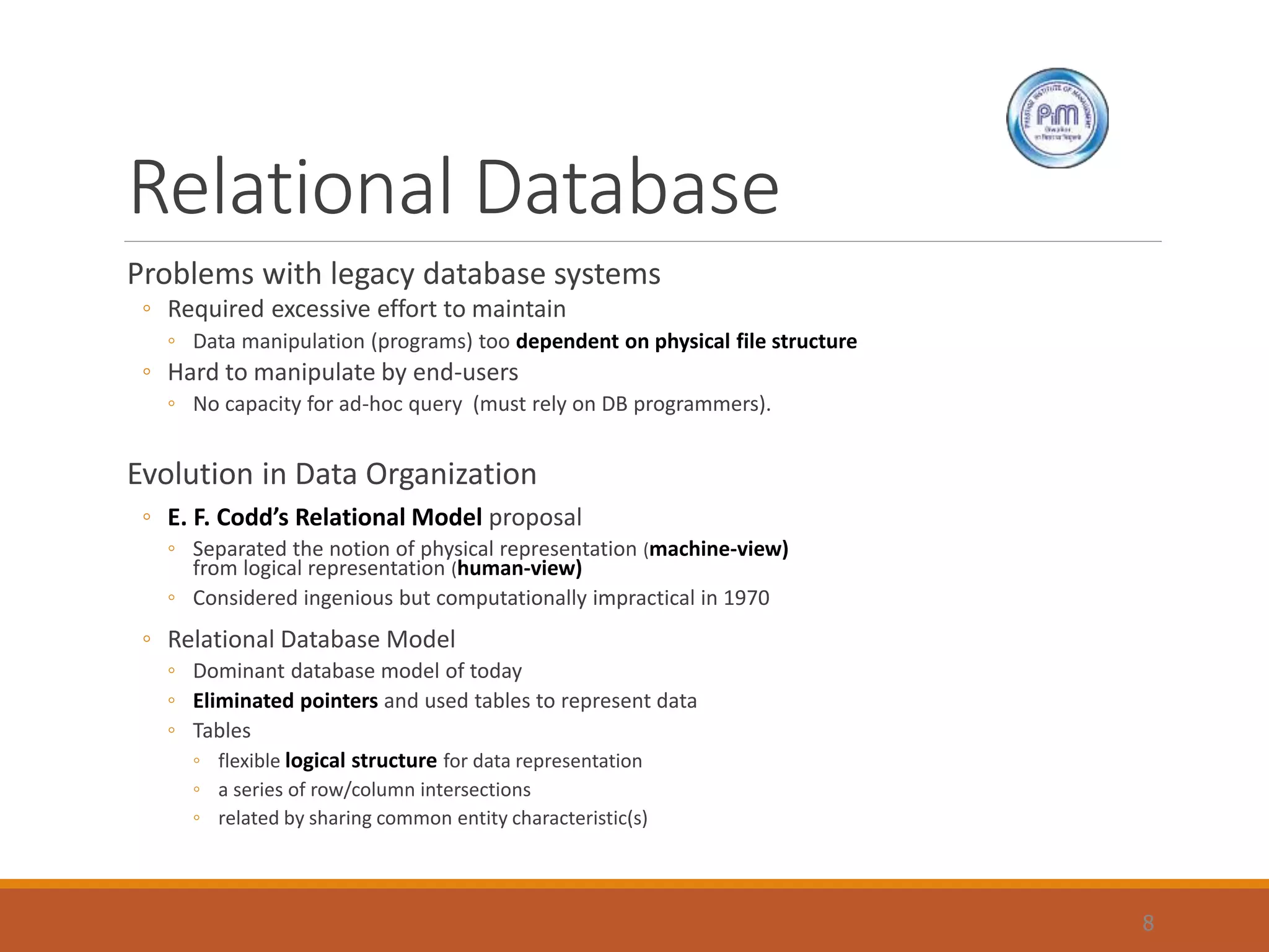
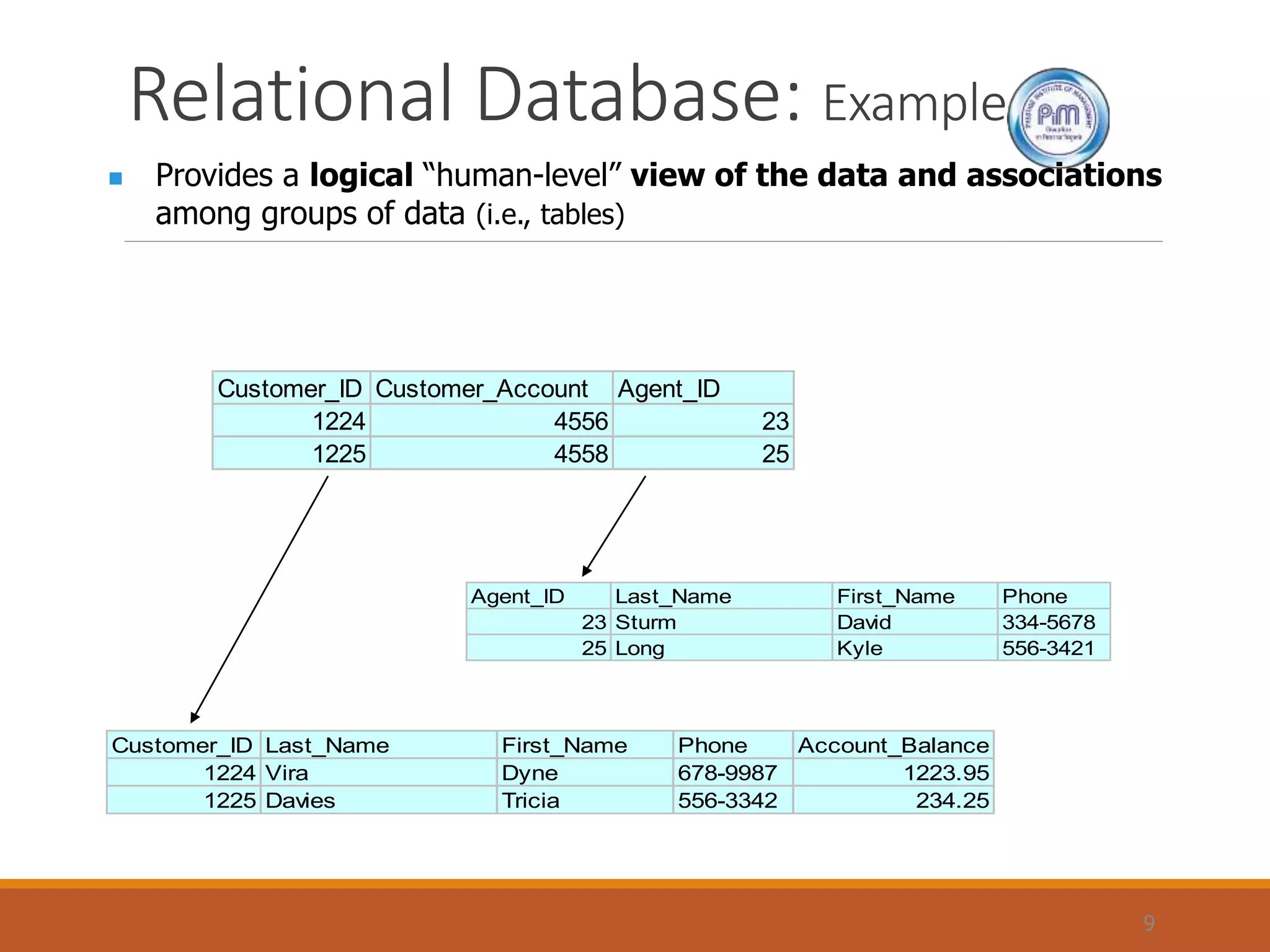
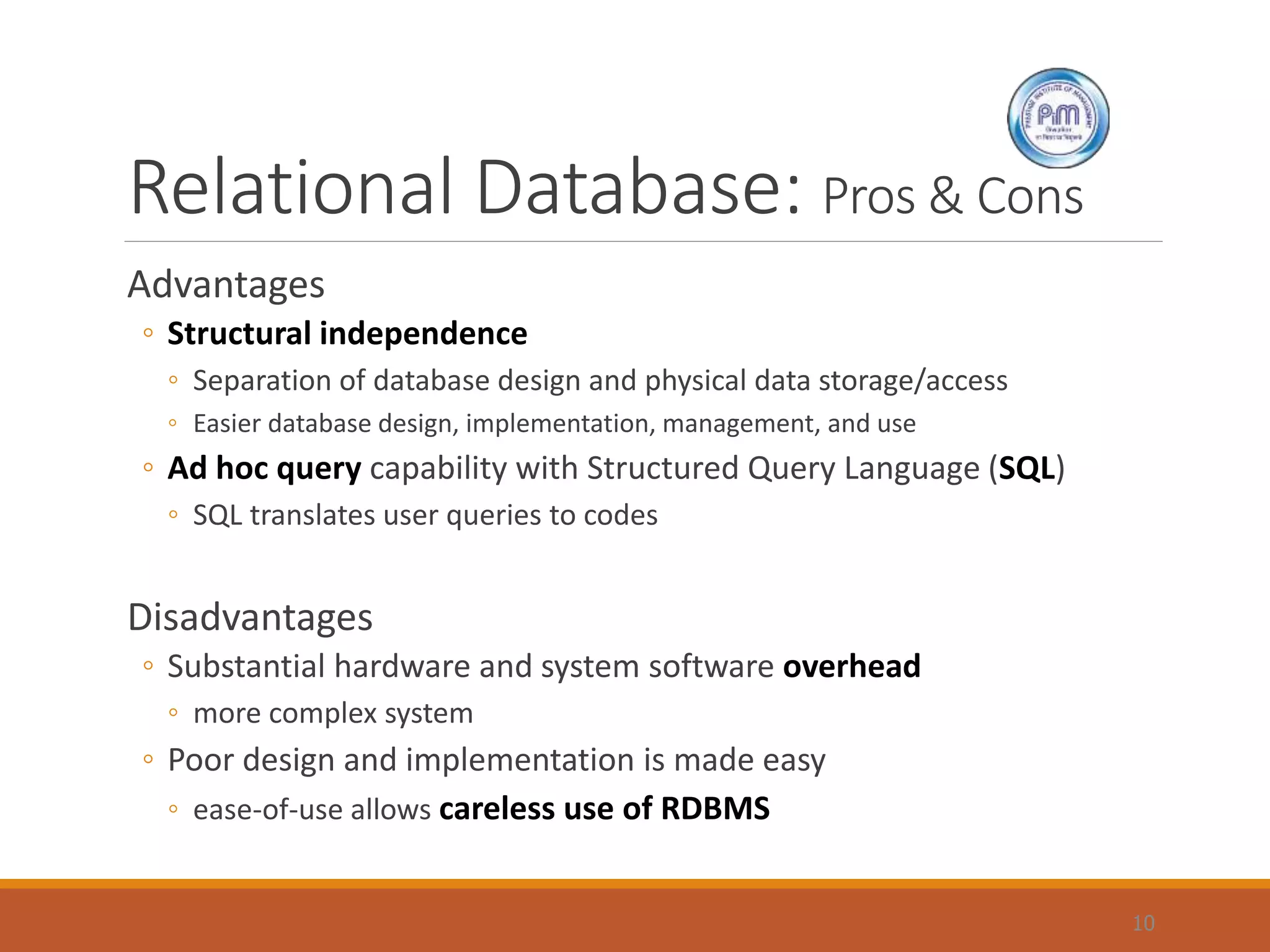
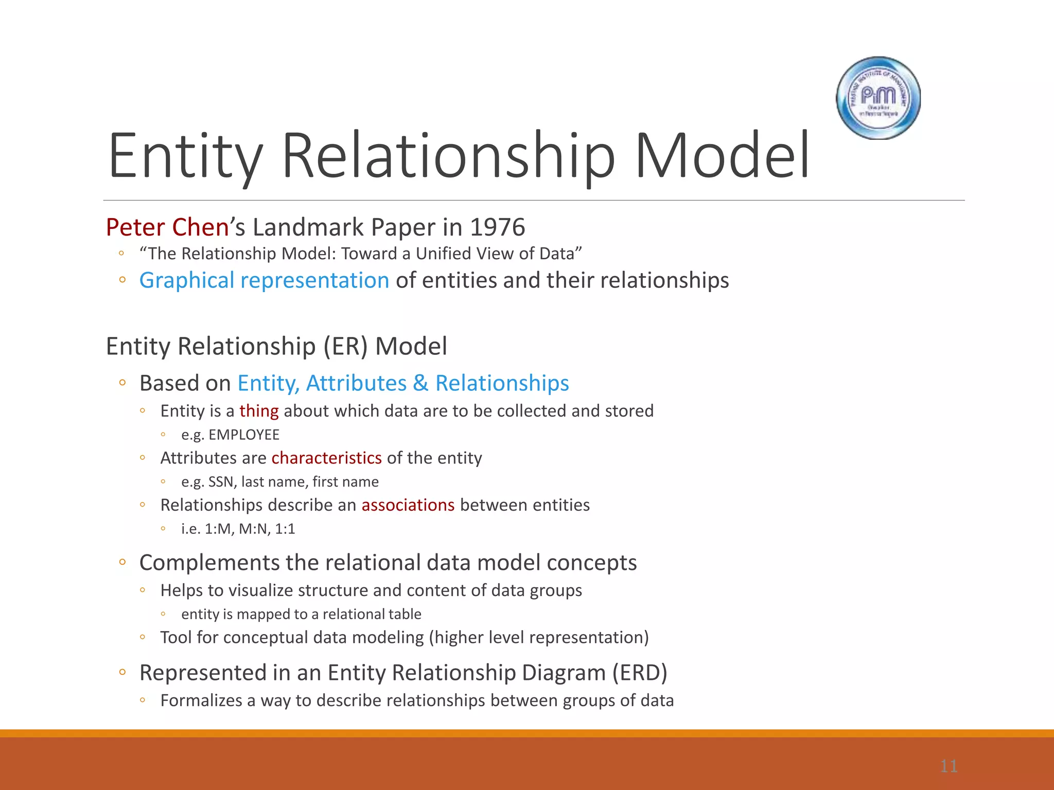
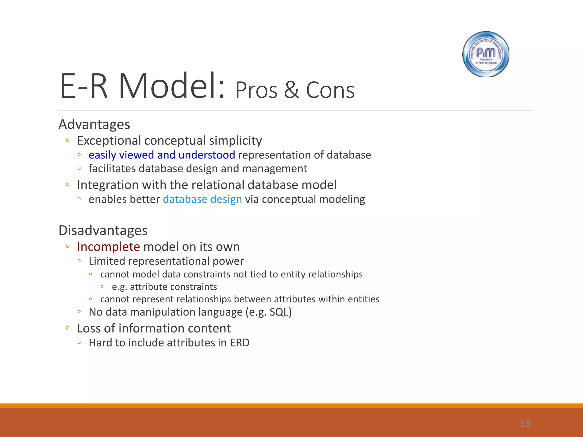

The document outlines the evolution of database models from the 1960s to the present, highlighting the transition from file-based systems to relational databases. It discusses the principles of relational databases, including their advantages such as structural independence and ad-hoc querying through SQL, as well as their disadvantages like system complexity and potential for poor design. The document also introduces the Entity-Relationship (E-R) model, emphasizing its role in visualizing data relationships and aiding in database design.