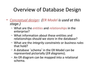
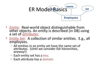
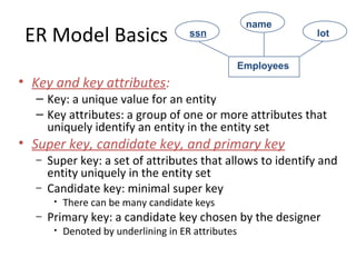
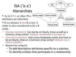
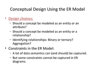
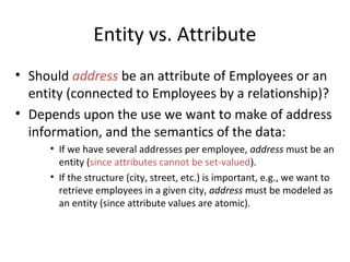
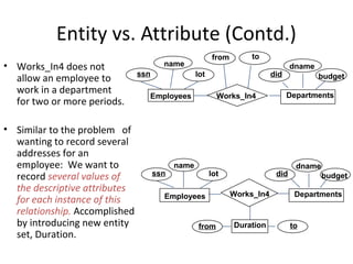
2. Database Design Process
• Requirement collection and analysis
– DB requirements and functional requirements
• Conceptual DB design using a high-level model
– Easier to understand and communicate with others
• Logical DB design (data model mapping)
– Conceptual schema is transformed from a high-level
data model into implementation data model
• Physical DB design
– Internal data structures and file organizations for DB
are specified
3. Overview of Database Design
• Conceptual design: (ER Model is used at this
stage.)
– What are the entities and relationships in the
enterprise?
– What information about these entities and
relationships should we store in the database?
– What are the integrity constraints or business rules
that hold?
– A database `schema’ in the ER Model can be
represented pictorially (ER diagrams).
– An ER diagram can be mapped into a relational
schema.
4. ER Model Basics
• Entity: Real-world object distinguishable from
other objects. An entity is described (in DB) using
a set of attributes.
• Entity Set: A collection of similar entities. E.g., all
employees.
– All entities in an entity set have the same set of
attributes. (Until we consider ISA hierarchies,
anyway!)
– Each entity set has a key.
– Each attribute has a domain.
Employees
ssn
name
lot
5. ER Model Basics
• Key and key attributes:
– Key: a unique value for an entity
– Key attributes: a group of one or more attributes that
uniquely identify an entity in the entity set
• Super key, candidate key, and primary key
– Super key: a set of attributes that allows to identify and
entity uniquely in the entity set
– Candidate key: minimal super key
• There can be many candidate keys
– Primary key: a candidate key chosen by the designer
• Denoted by underlining in ER attributes
Employees
ssn
name
lot
6. ER Model Basics (Contd.)
• Relationship: Association among two or more
entities. e.g., Jack works in Pharmacy department.
• Relationship Set: Collection of similar relationships.
– An n-ary relationship set R relates n entity sets E1 ... En;
each relationship in R involves entities e1 in E1, ..., en in En
• Same entity set could participate in different relationship sets, or in
different “roles” in same set.
lot
dname
budgetdid
since
name
Works_In DepartmentsEmployees
ssn
Reports_To
lot
name
Employees
subor-
dinate
super-
visor
ssn
7. Key Constraints
• Consider Works_In:
An employee can
work in many
departments; a dept
can have many
employees.
• In contrast, each dept
has at most one
manager, according
to the key
constraint on
Manages.
Many-to-Many1-to-1 1-to Many Many-to-1
dname
budgetdid
since
lot
name
ssn
ManagesEmployees Departments
8. Example ER
• An ER diagram represents
several assertions about the
real world. What are they?
• When attributes are added,
more assertions are made.
• How can we ensure they
are correct?
• A DB is judged correct if it
captures ER diagram
correctly.
Students
Professor teaches
Department
faculty
major
offers
Courses
enrollment
advisor
9. Exercises
• Is double major allowed?
• Can a student have more
than 1 advisor?
• Is joint appointment of
faculty possible?
• Can two profs share to
teach the same course?
• Can a professor teach more
than one course?
• Can a professor stay
without affiliated with a
department?
Students
Professor teaches
Department
faculty
major
offers
Courses
enrollment
advisor
10. Participation Constraints
• Does every department have a manager?
– If so, this is a participation constraint: the participation of
Departments in Manages is said to be total (vs. partial).
• Every Departments entity must appear in an instance of
the Manages relationship.
lot
name dname
budgetdid
since
name dname
budgetdid
since
Manages
since
DepartmentsEmployees
ssn
Works_In
11. Weak Entities
• A weak entity can be identified uniquely only by considering the
primary key of another (owner) entity.
– Owner entity set and weak entity set must participate in a one-to-
many relationship set (one owner, many weak entities).
– Weak entity set must have total participation in this identifying
relationship set.
lot
name
agepname
DependentsEmployees
ssn
Policy
cost
12. ISA (`is a’)
Hierarchies
• Overlap constraints: Can Joe be an Hourly_Emps as well as a
Contract_Emps entity? (default: disallowed; A overlaps B)
• Covering constraints: Does every Employees entity also have to
be an Hourly_Emps or a Contract_Emps entity? (default: no; A
AND B COVER C)
• Reasons for using ISA:
– To add descriptive attributes specific to a subclass.
– To identify entities that participate in a relationship.
Contract_Emps
name
ssn
Employees
lot
hourly_wages
ISA
Hourly_Emps
contractid
hours_worked As in C++, or other PLs,
attributes are inherited.
If we declare A ISA B, every A
entity is also considered to be a B
entity.
13. Aggregation
• Used when we have to
model a relationship
involving (entitity sets
and) a relationship set.
– Aggregation allows us
to treat a relationship
set as an entity set for
purposes of
participation in (other)
relationships.
Aggregation vs. ternary relationship:
Monitors is a distinct relationship,
with a descriptive attribute.
Also, can say that each sponsorship
is monitored by at most one employee.
budgetdidpid
started_on
pbudget
dname
until
DepartmentsProjects Sponsors
Employees
Monitors
lot
name
ssn
since
14. Conceptual Design Using the ER Model
• Design choices:
– Should a concept be modeled as an entity or an
attribute?
– Should a concept be modeled as an entity or a
relationship?
– Identifying relationships: Binary or ternary?
Aggregation?
• Constraints in the ER Model:
– A lot of data semantics can (and should) be captured.
– But some constraints cannot be captured in ER
diagrams.
15. Entity vs. Attribute
• Should address be an attribute of Employees or an
entity (connected to Employees by a relationship)?
• Depends upon the use we want to make of address
information, and the semantics of the data:
• If we have several addresses per employee, address must be an
entity (since attributes cannot be set-valued).
• If the structure (city, street, etc.) is important, e.g., we want to
retrieve employees in a given city, address must be modeled as
an entity (since attribute values are atomic).
16. Entity vs. Attribute (Contd.)
• Works_In4 does not
allow an employee to
work in a department
for two or more periods.
• Similar to the problem of
wanting to record several
addresses for an
employee: We want to
record several values of
the descriptive attributes
for each instance of this
relationship. Accomplished
by introducing new entity
set, Duration.
name
Employees
ssn lot
Works_In4
from to
dname
budgetdid
Departments
dname
budgetdid
name
Departments
ssn lot
Employees Works_In4
Durationfrom to
17. Entity vs. Relationship
• First ER diagram OK if a
manager gets a separate
discretionary budget for
each dept.
• What if a manager gets a
discretionary budget
that covers all
managed depts?
– Redundancy: dbudget
stored for each dept
managed by manager.
– Misleading: Suggests
dbudget associated with
department-mgr
combination.
Manages2
name dname
budgetdid
Employees Departments
ssn lot
dbudgetsince
dname
budgetdid
DepartmentsManages2
Employees
name
ssn lot
since
Managers dbudget
ISA
This fixes the
problem!
18. Binary vs. Ternary Relationships
• If each policy is
owned by just 1
employee, and
each dependent is
tied to the
covering policy,
first diagram is
inaccurate.
• What are the
additional
constraints in the
2nd diagram?
agepname
DependentsCovers
name
Employees
ssn lot
Policies
policyid cost
Beneficiary
agepname
Dependents
policyid cost
Policies
Purchaser
name
Employees
ssn lot
Bad design
Better design
19. Binary vs. Ternary Relationships (Contd.)
• Previous example illustrated a case when two
binary relationships were better than one ternary
relationship.
• An example in the other direction: a ternary
relation Contracts relates entity sets Parts,
Departments and Suppliers, and has descriptive
attribute qty. No combination of binary
relationships is an adequate substitute:
– S “can-supply” P, D “needs” P, and D “deals-with” S
does not imply that D has agreed to buy P from S.
– How do we record qty?
20. Summary of Conceptual Design
• Conceptual design follows requirements analysis,
– Yields a high-level description of data to be stored
• ER model popular for conceptual design
– Constructs are expressive, close to the way people
think about their applications.
• Basic constructs: entities, relationships, and
attributes (of entities and relationships).
• Some additional constructs: weak entities, ISA
hierarchies, and aggregation.
• Note: There are many variations on ER model.
21. Summary of ER (Contd.)
• Several kinds of integrity constraints can be
expressed in the ER model: key constraints,
participation constraints, and overlap/covering
constraints for ISA hierarchies. Some foreign key
constraints are also implicit in the definition of a
relationship set.
– Some constraints (notably, functional dependencies)
cannot be expressed in the ER model.
– Constraints play an important role in determining the
best database design for an enterprise.
22. Summary of ER (Contd.)
• ER design is subjective. There are often many
ways to model a given scenario! Analyzing
alternatives can be tricky, especially for a large
enterprise. Common choices include:
– Entity vs. attribute, entity vs. relationship, binary or
n-ary relationship, whether or not to use ISA
hierarchies, and whether or not to use aggregation.
• Ensuring good database design: resulting
relational schema should be analyzed and
refined further. FD information and
normalization techniques are especially useful.
23. Exercise
• What can you
say about
policy of the
bank from the
ER diagram?
• What can you
say about the
policy of the
company?
balanceacct#
AccountCustAcct
name
Customer
ssn addr
deptid budget
Dept
Manages
name
Employees
ssn lot
24. Design Exercise
• Design a DB using ER, and sketch the resulting diagram. State any
important assumptions you made in reaching the design. Show
explicitly whether relationships are 1-1, 1-M, or N-M.
– UMW registrar’s office: It maintains data about each
class, including the instructor, students, enrollment,
time and place of the class meetings. For each student-
class pair, a grade is recorded.
– Hospital: It maintains all patients visited, including age
and address. It also keeps track of the information about
billing, visits, data, reason for visit, and treatment.
Editor's Notes
The important issue of how to map from ER diagrams to relational tables is deferred until the relational model and the integrity constraints it supports have been introduced. ER to relational mapping, together with a discussion of the related SQL commands, is discussed in Chapter 3.
The slides for this text are organized into several modules. Each lecture contains about enough material for a 1.25 hour class period. (The time estimate is very approximate--it will vary with the instructor, and lectures also differ in length; so use this as a rough guideline.) This covers Lectures 1 and 2 (of 6) in Module (5).
Module (1): Introduction (DBMS, Relational Model)
Module (2): Storage and File Organizations (Disks, Buffering, Indexes)
Module (3): Database Concepts (Relational Queries, DDL/ICs, Views and Security)
Module (4): Relational Implementation (Query Evaluation, Optimization)
Module (5): Database Design (ER Model, Normalization, Physical Design, Tuning)
Module (6): Transaction Processing (Concurrency Control, Recovery)
Module (7): Advanced Topics