Download to read offline
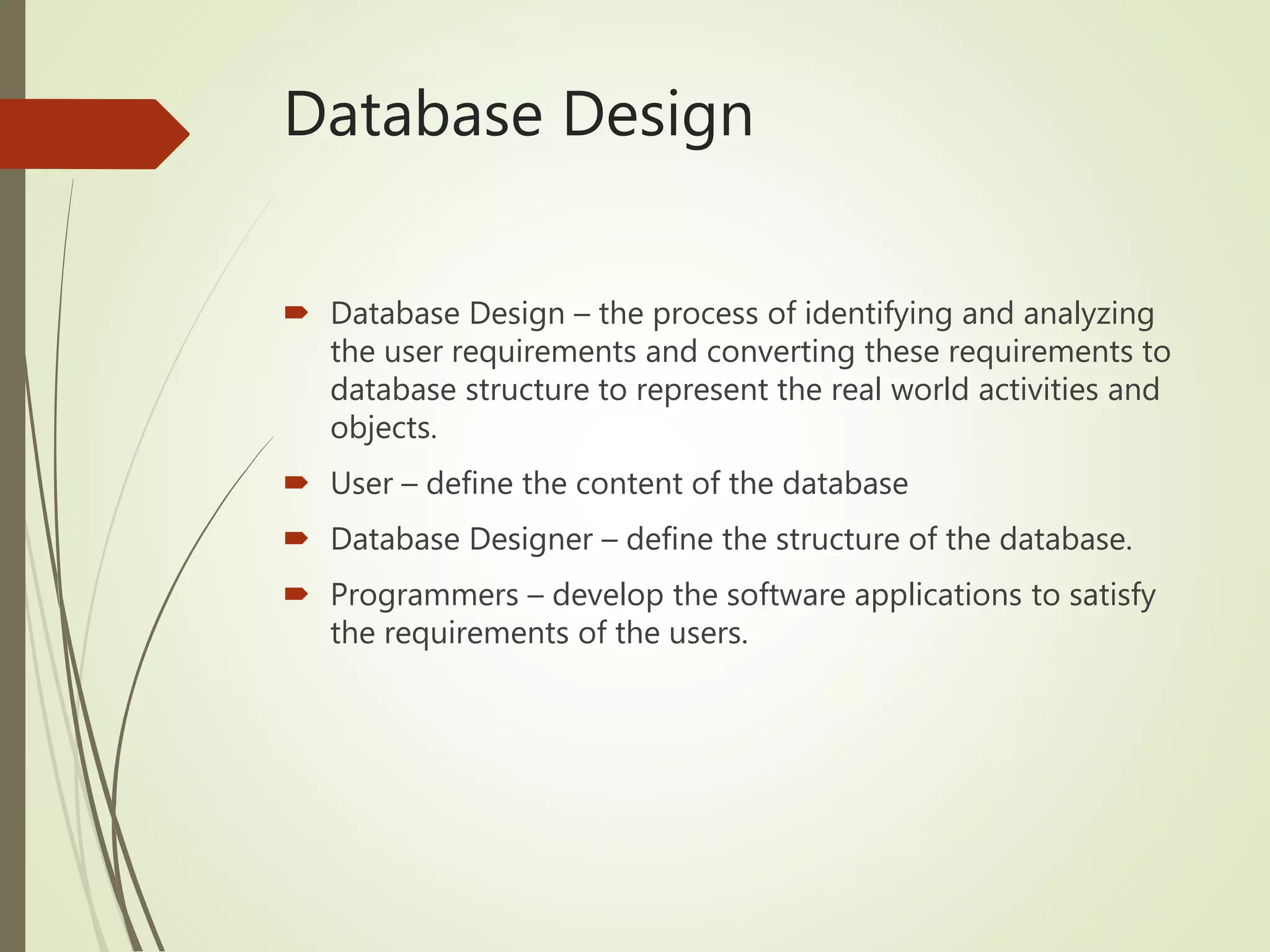
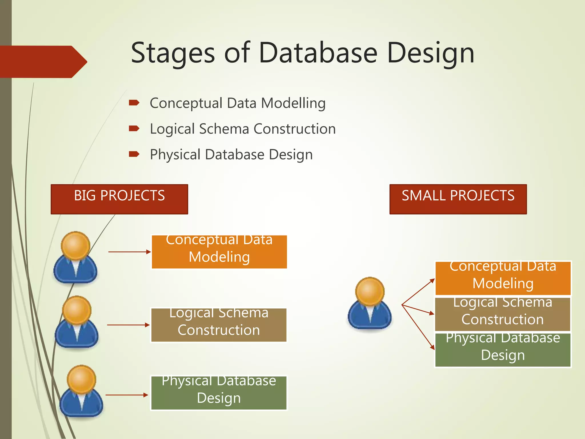
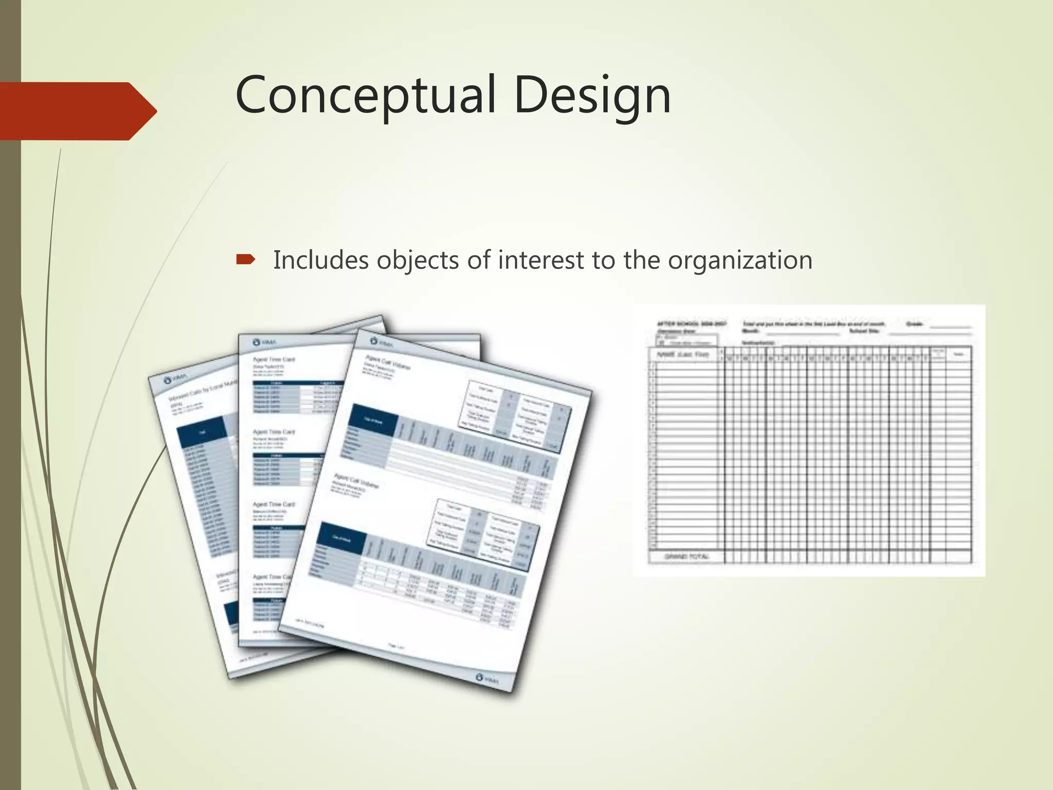
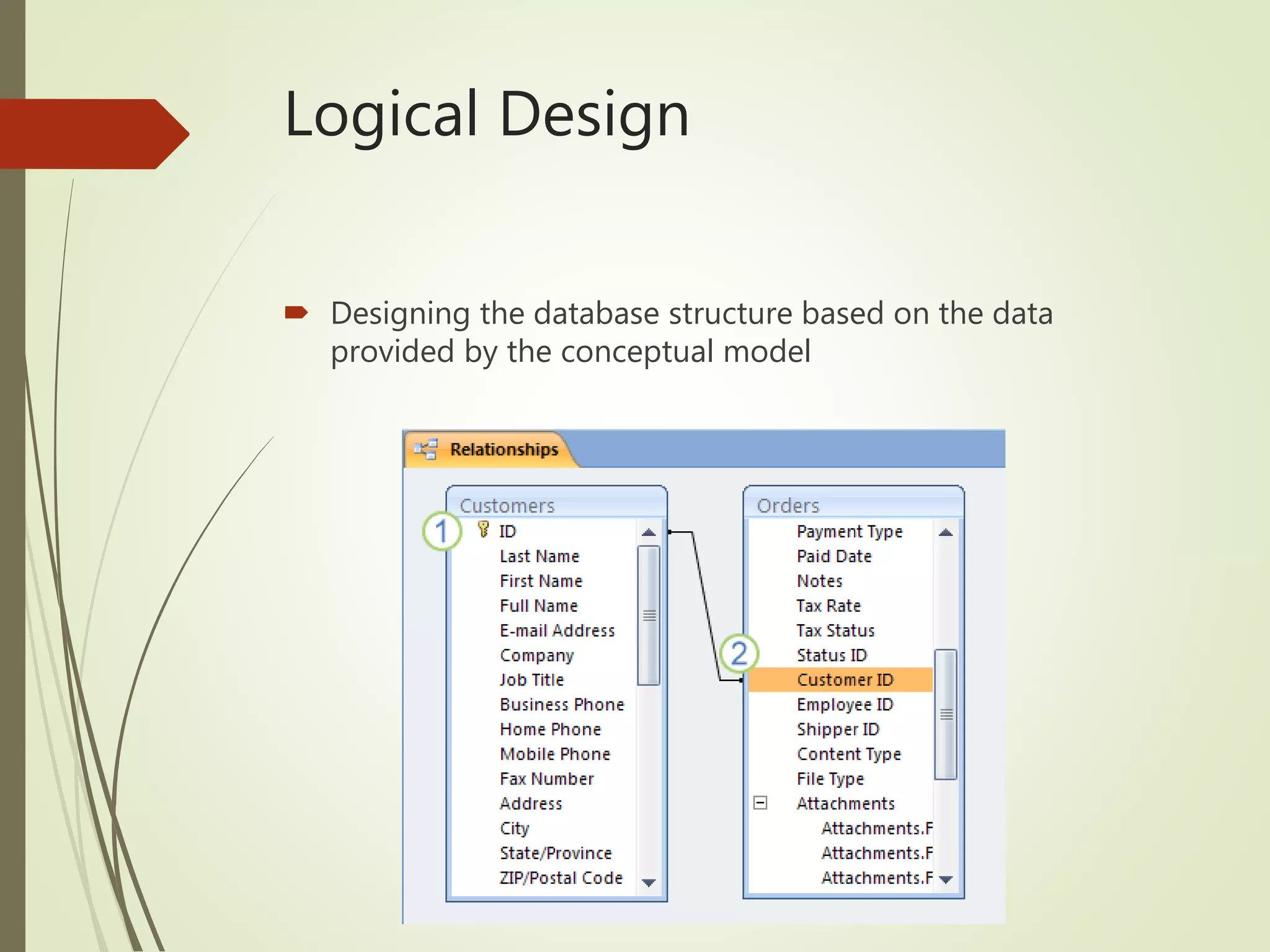
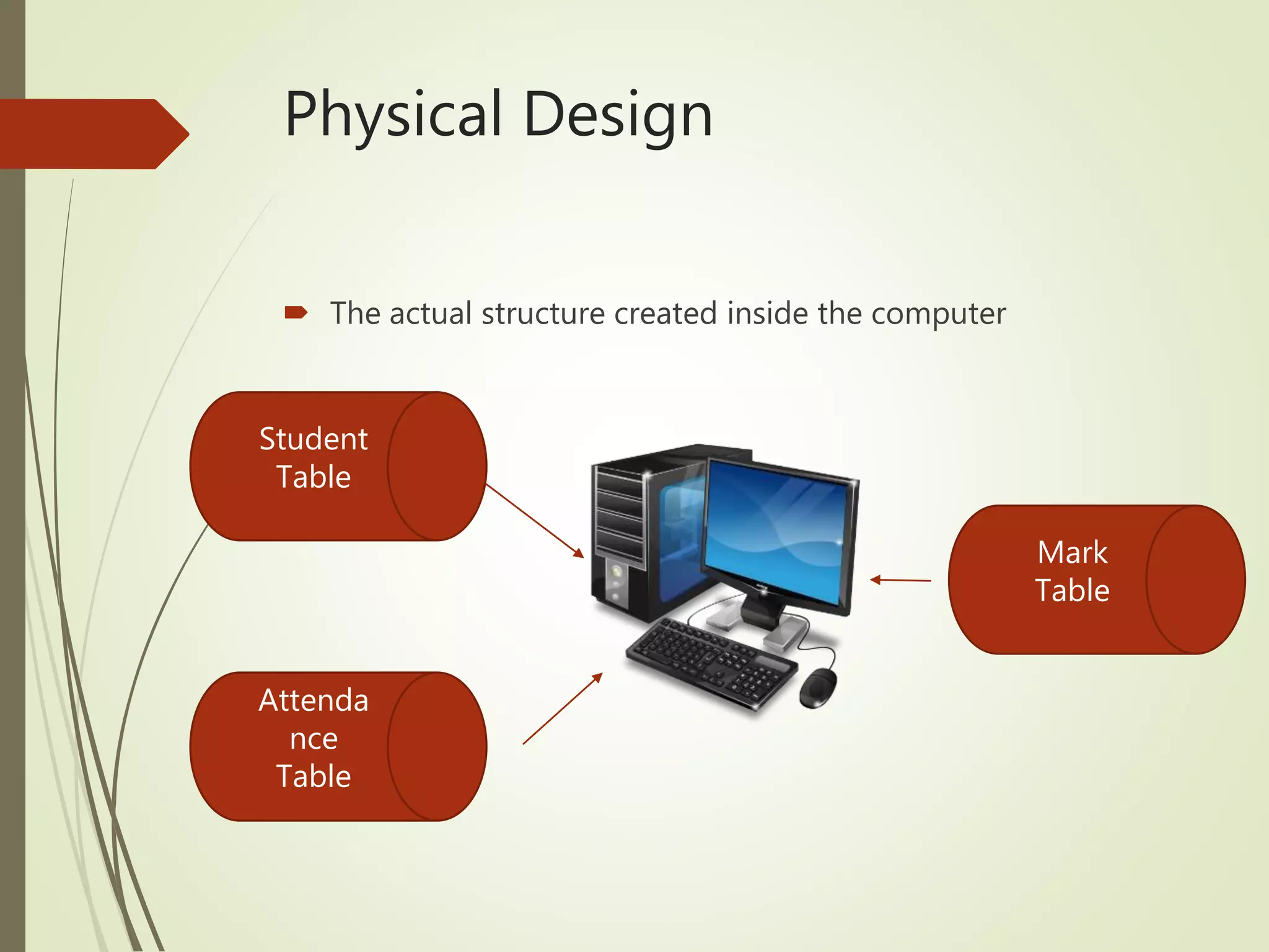
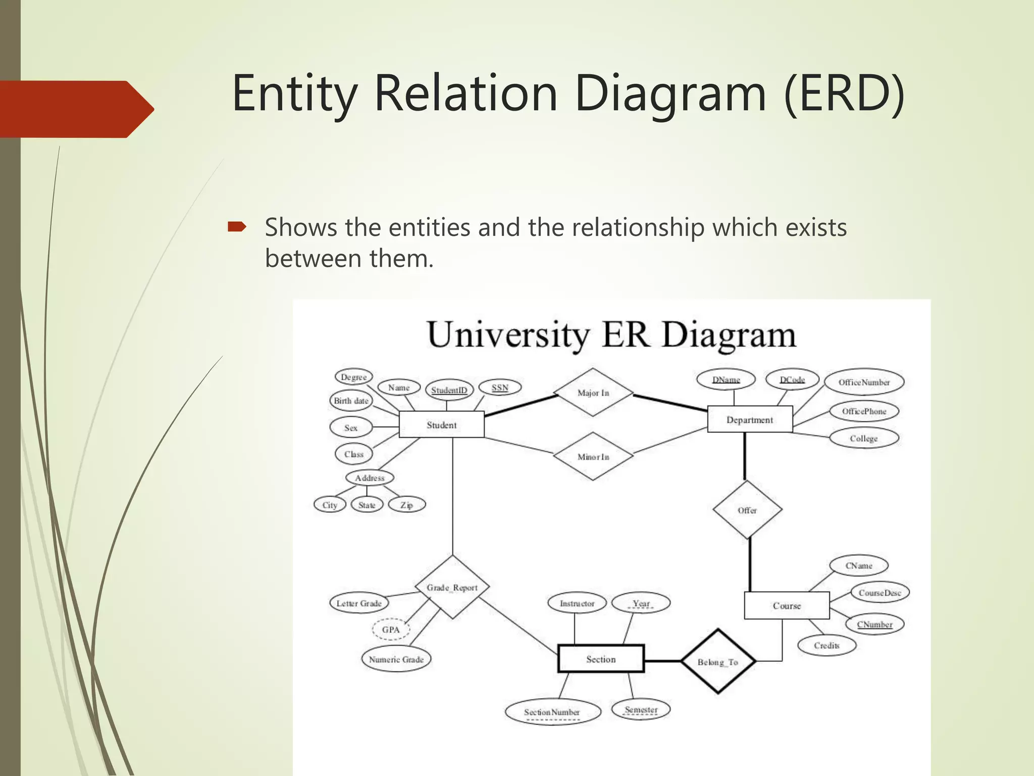
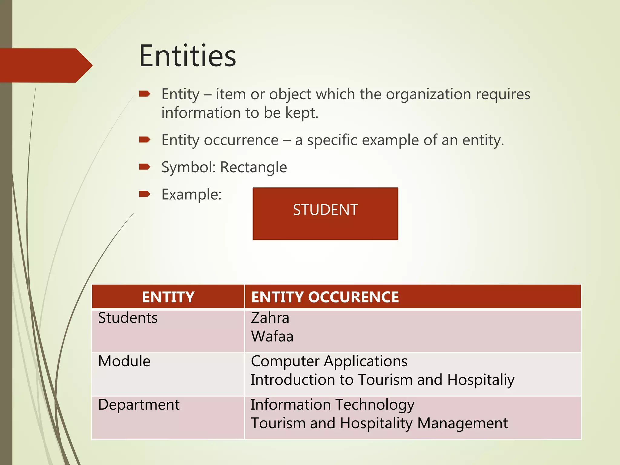
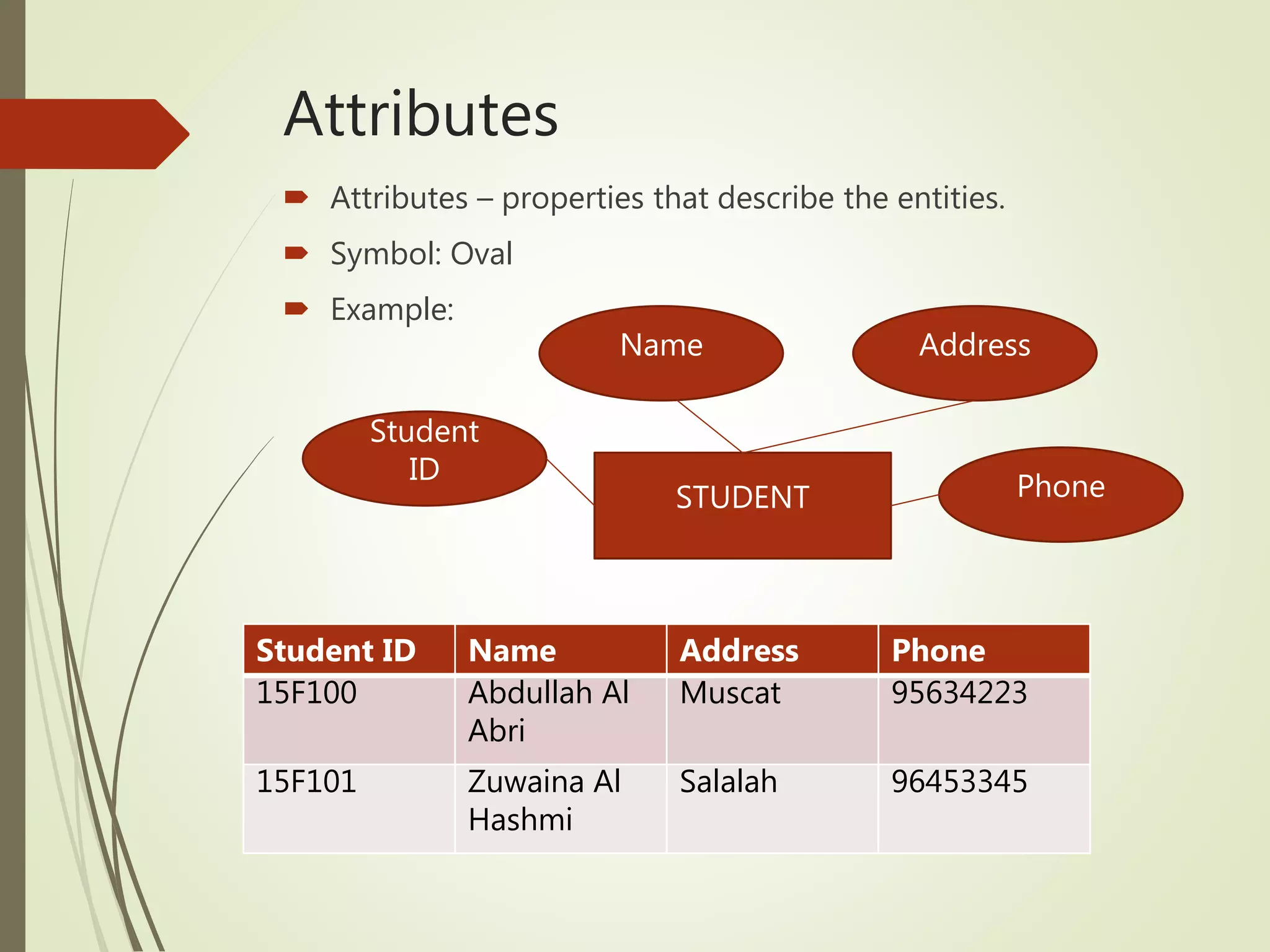
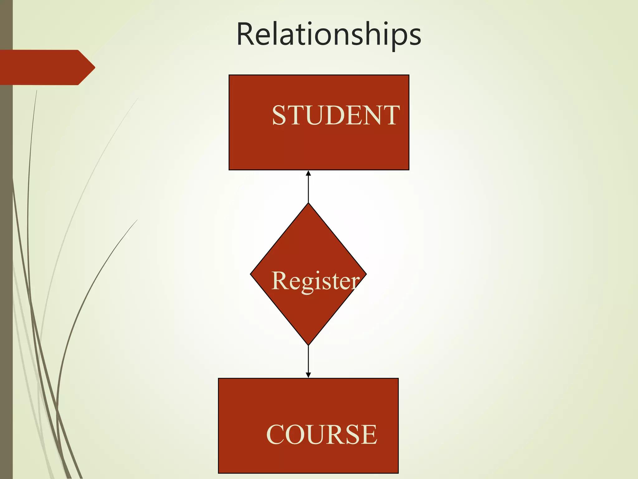
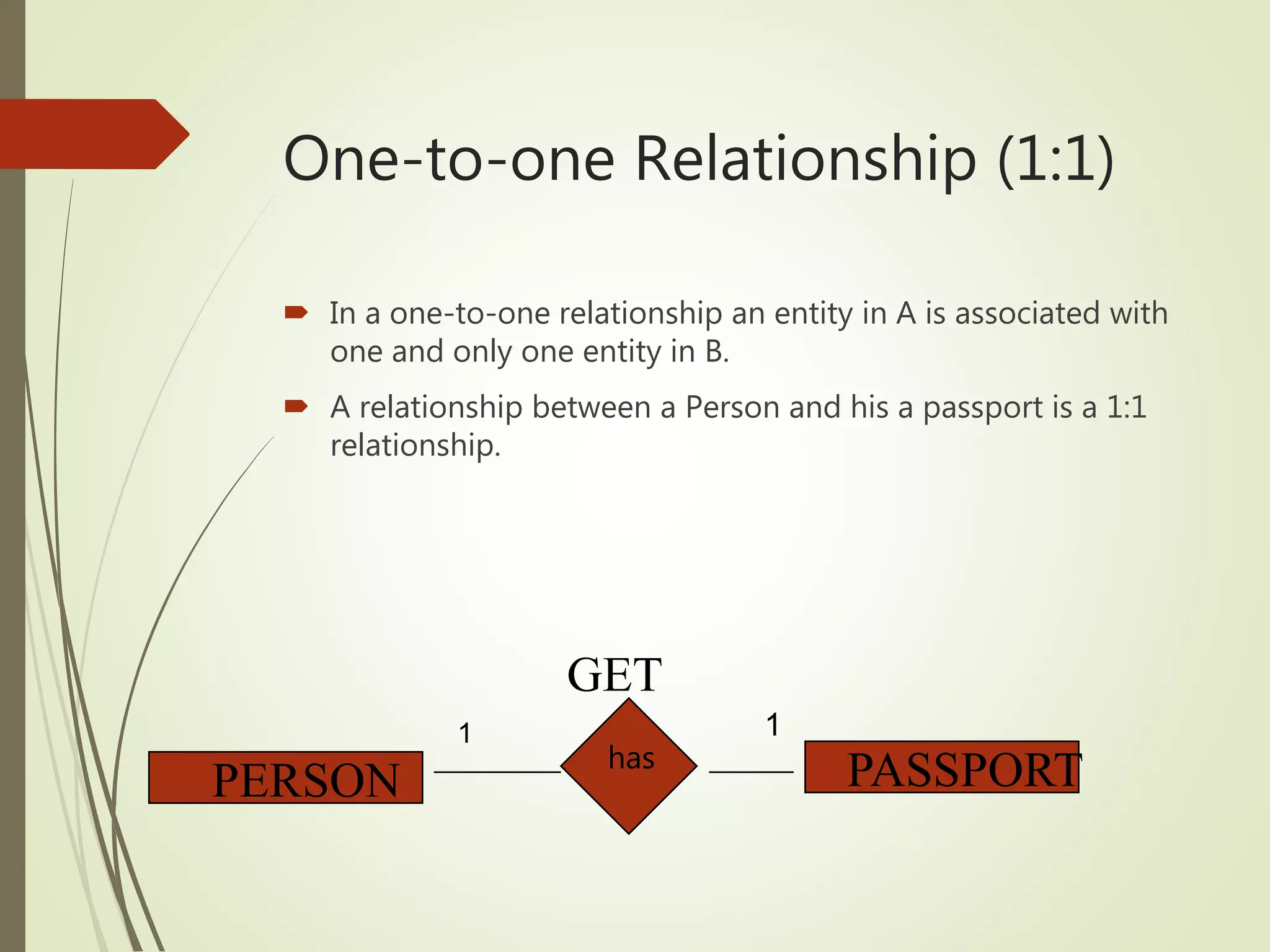
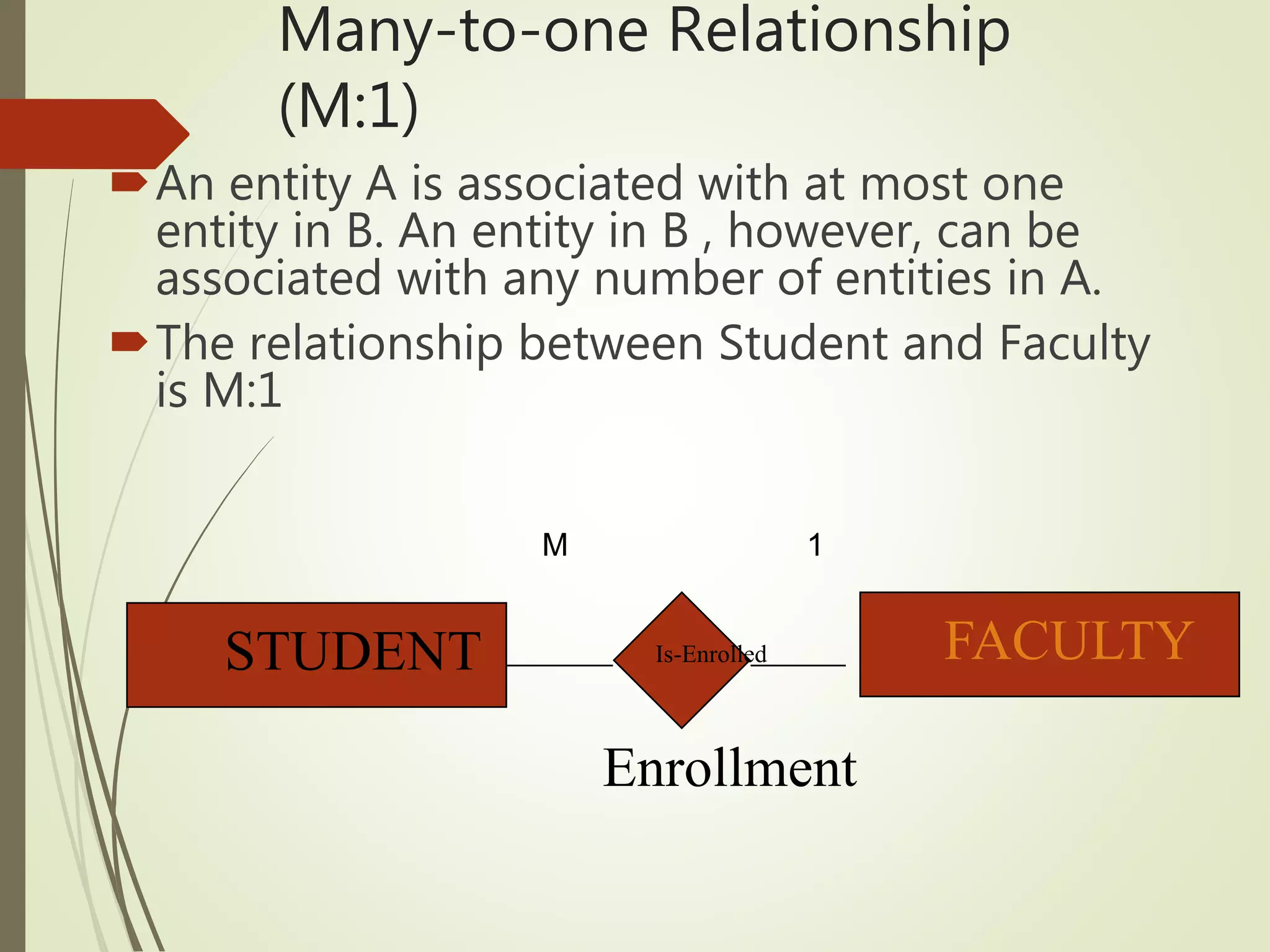
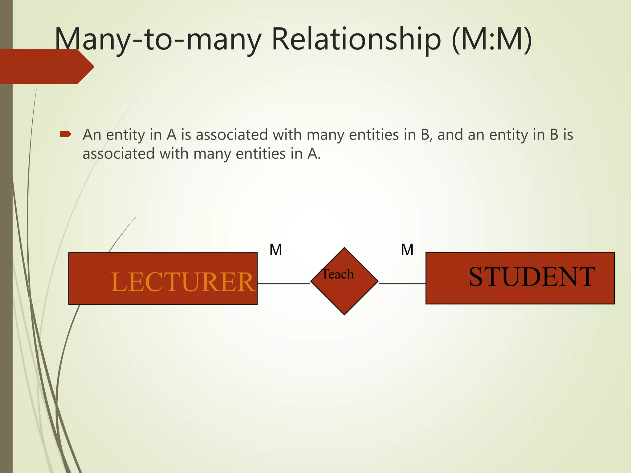


This document discusses data models and database design. It defines the key stages of database design as conceptual data modeling, logical schema construction, and physical database design. The document describes conceptual modeling techniques like entity relationship diagrams and normalization. It defines entities, attributes, and relationships. Different relationship types like one-to-one, one-to-many, and many-to-many are described. The document provides examples of entities, attributes, and relationships in an entity relationship diagram.