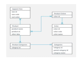
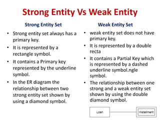
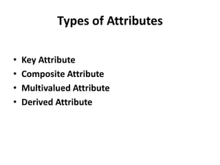
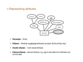
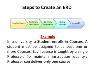
E-R Model
&
E-R Diagram
What is the ER Model?
ENTITY RELATIONAL (ER) MODEL is a high-
level conceptual data model diagram. ER
modeling helps you to analyze data
requirements systematically to produce a
well-designed database. The Entity-Relation
model represents real-world entities and
the relationship between them. It is
considered a best practice to complete ER
modeling before implementing your
database.
What is ER Diagrams?
ENTITY-RELATIONSHIPDIAGRAM
(ERD) displays the relationships of entity set
stored in a database. In other words, we can
say that ER diagrams help you to explain the
logical structure of databases. At first look, an
ER diagram looks very similar to the
flowchart. However, ER Diagram includes
many specialized symbols, and its meanings
make this model unique. The purpose of ER
Diagram is to represent the entity framework
infrastructure.
Why use ER Diagrams?
• Helps you to define terms related to entity
relationship modeling
• Provide a preview of how all your tables should
connect, what fields are going to be on each
table
• Helps to describe entities, attributes,
relationships
• ER diagrams are relational tables which allows
you to build databases quickly
• ER diagrams can be used as a blueprint
• ERD is allowed you to communicate with the
logical structure of the database to users
Components of the ER Diagram
This model is based on three basic concepts:
• Entities
• Attributes
• Relationships
• For example, in a University database, we
might have entities for Students, Courses, and
Lecturers. Students entity can have attributes
like Rollno, Name, and DeptID. They might
have relationships with Courses and Lecturers.
WHAT IS ENTITY?
A real-world thing either living or non-living
that is easily recognizable and non
recognizable. It may be a physical thing or
simply a fact about the enterprise or an event
that happens in the real world.
An entity can be place, person, object, event
or a concept, which stores data in the
database. The characteristics of entities are
must have an attribute, and a unique key.
Examples of entities:
Person: Employee, Student, Patient
Place: Store, Building
Object: Machine, product, and Car
Event: Sale, Registration, Renewal
Concept: Account, Course
Entity set:
An entity set is a group of similar kind of entities. It
may contain entities with attribute sharing similar
values. Entities are represented by their
properties, which also called attributes. All
attributes have their separate values. For example,
a student entity may have a name, age, class, as
attributes.
Relationship
Relationship is nothing but an association
among two or more entities. E.g., Tom works in
the Chemistry department.
For example:
• You are attending this lecture
• I am giving the lecture
• we can classify relationships according to relationship-types:
• A student attends a lecture
• A lecturer is giving a lecture.
Weak Entities
A weak entity is a type of entity which doesn't have its
key attribute. It can be identified uniquely by
considering the primary key of another entity. For that,
weak entity sets need to have participation.
Strong Entity Vs Weak Entity
Strong Entity Set
• Strong entity set always has a
primary key.
• It is represented by a
rectangle symbol.
• It contains a Primary key
represented by the underline
symbol.
• In the ER diagram the
relationship between two
strong entity set shown by
using a diamond symbol.
Weak Entity Set
• weak entity set does not have
primary key.
• It is represented by a double
recta
• It contains a Partial Key which
is represented by a dashed
underline symbol.ngle
symbol.
• The relationship between one
strong and a weak entity set
shown by using the double
diamond symbol.
Attributes
The attribute is used to describe the property of an
entity. An attribute is represented by an Ellipse.
For example, a student might have attributes: id, name,
age, phone_no, etc.
Types of Attributes
• Key Attribute
• Composite Attribute
• Multivalued Attribute
• Derived Attribute
Key Attribute
The key attribute is used to represent the main
characteristics of an entity. It represents a primary
key. The key attribute is represented by an ellipse
with the text underlined.
Composite Attribute
An attribute that composed of many other attributes is
known as a composite attribute. The composite attribute
is represented by an ellipse, and those ellipses are
connected with an ellipse.
Multivalued Attribute
An attribute can have more than one value. These
attributes are known as a multivalued attribute. The
double oval is used to represent multivalued attribute.
For example, a student can have more than one phone
number.
Derived Attribute
An attribute that can be derived from other attribute is
known as a derived attribute. It can be represented by a
dashed ellipse.
For example, A person's age changes over time and can
be derived from another attribute like Date of birth.
Relationship
a. One-to-One Relationship
When only one instance of an entity is associated with
the relationship, then it is known as one to one
relationship.
For example, A female can marry to one male, and a
male can marry to one female.
b. One-to-many relationship
When only one instance of the entity on the left, and
more than one instance of an entity on the right
associates with the relationship then this is known as a
one-to-many relationship.
For example, Scientist can invent many inventions, but
the invention is done by the only specific scientist.
c. Many-to-one relationship
When more than one instance of the entity on the
left, and only one instance of an entity on the right
associates with the relationship then it is known as a
many-to-one relationship.
For example, Student enrolls for only one course, but
a course can have many students.
d. Many-to-many relationship
When more than one instance of the entity on the
left, and more than one instance of an entity on the
right associates with the relationship then it is known
as a many-to-many relationship.
For example, Employee can assign by many projects
and project can have many employees.
ER- Diagram Notations
• Rectangles: This symbol represent entity types
• Ellipses : Symbol represent attributes
• Diamonds: This symbol represents relationship
types
• Lines: It links attributes to entity types and entity
types with other relationship types
• Primary key: attributes are underlined
• Double Ellipses: Represent multi-valued
attributes
ER- Diagram Symbols
Steps to Create an ERD
Example
In a university, a Student enrolls in Courses. A
student must be assigned to at least one or
more Courses. Each course is taught by a single
Professor. To maintain instruction quality,a
Professor can deliver only one course
Step 1) Entity Identification
We have three entities
• Student
• Course
• Professor
Step 2) Relationship Identification
We have the following two relationships
• The student is assigned a course
• Professor delivers a course
Step 3) Cardinality Identification
For them problem statement we know that,
• A student can be assigned multiple courses
• A Professor can deliver only one course
Step 4) Identify Attributes
Entity Primary Key Attribute
Student Student_ID StudentName
Professor Employee_ID ProfessorName
Course Course_ID CourseName
Step 5) Create the ERD
A more modern representation of ERD Diagram
Draw E-R diagram for Hospital management System.
Identifying the Attributes & relationships
a. Hospital has a set of patients.
Therefore the relations is 1……..N.
b. Hospital has a set of doctors.
Therefore the relations is 1……..N.
c. Doctor are associated with each patient.
Therefore the relations is N……..1.
d. Each patient has record of various test and
examination conducted.
Therefore the relations is 1……..N.
E-R diagram for Hospital management System.
Example: E-R diagram
Example: E-R Diagram
Generalization
• Generalization is like a bottom-up approach in which
two or more entities of lower level combine to form a
higher level entity if they have some attributes in
common.
• In generalization, an entity of a higher level can also
combine with the entities of the lower level to form a
further higher level entity.
• Generalization is more like subclass and superclass
system, but the only difference is the approach.
Generalization uses the bottom-up approach.
• In generalization, entities are combined to form a more
generalized entity, i.e., subclasses are combined to make
a superclass.
For example, Faculty and Student entities can be generalized
and create a higher level entity Person.
Specialization
• Specialization is a top-down approach, and it is
opposite to Generalization. In specialization, one
higher level entity can be broken down into two
lower level entities.
• Specialization is used to identify the subset of an
entity set that shares some distinguishing
characteristics.
• Normally, the superclass is defined first, the
subclass and its related attributes are defined
next, and relationship set are then added.
For example: In an Employee management system, EMPLOYEE
entity can be specialized as TESTER or DEVELOPER based on
what role they play in the company.
Aggregation
In aggregation, the relation between two
entities is treated as a single entity. In
aggregation, relationship with its corresponding
entities is aggregated into a higher level entity.
For example: Center entity offers the Course entity act
as a single entity in the relationship which is in a
relationship with another entity visitor. In the real world,
if a visitor visits a coaching center then he will never
enquiry about the Course only or just about the Center
instead he will ask the enquiry about both.
Reduction of E-R Diagram into Table
Codd's Rule for Relational DBMS
Rule 1: Information rule
All information(including metadata) is to be represented as stored
data in cells of tables. The rows and columns have to be strictly
unordered.
Rule 2: Guaranted Access
Each unique piece of data(atomic value) should be accesible by :
Table Name + Primary Key(Row) + Attribute(column).
NOTE: Ability to directly access via POINTER is a violation of this rule.
Rule 3: Systematic treatment of NULL
Null has several meanings, it can mean missing data, not applicable
or no value. It should be handled consistently. Also, Primary key must
not be null, ever. Expression on NULL must give null.
Rule 4: Active Online Catalog
Database dictionary(catalog) is the structure description of the
complete Database and it must be stored online. The Catalog must
be governed by same rules as rest of the database. The same query
language should be used on catalog as used to query database.
Rule 5: Powerful and Well-Structured Language
One well structured language must be there to provide all manners
of access to the data stored in the database. Example: SQL, etc. If
the database allows access to the data without the use of this
language, then that is a violation.
Rule 6: View Updation Rule
All the view that are theoretically updatable should be updatable by
the system as well.
Rule 8: Physical Data Independence
The physical storage of data should not matter to the system. If say,
some file supporting table is renamed or moved from one disk to
another, it should not effect the application.
Rule 9: Logical Data Independence
If there is change in the logical structure(table structures) of the
database the user view of data should not change. Say, if a table is
split into two tables, a new view should give result as the join of the
two tables. This rule is most difficult to satisfy.
Rule 7: Relational Level Operation
There must be Insert, Delete, Update operations at each level of
relations. Set operation like Union, Intersection and minus should
also be supported.
Rule 10: Integrity Independence
The database should be able to enforce its own integrity rather
than using other programs. Key and Check constraints, trigger etc,
should be stored in Data Dictionary. This also make RDBMS
independent of front-end.
Rule 11: Distribution Independence
A database should work properly regardless of its distribution
across a network. Even if a database is geographically distributed,
with data stored in pieces, the end user should get an impression
that it is stored at the same place. This lays the foundation of
distributed database.
Rule 12: Nonsubversion Rule
If low level access is allowed to a system it should not be able to
subvert or bypass integrity rules to change the data. This can be
achieved by some sort of looking or encryption.

E_R-Diagram (2).pptx

  • 1.
  • 2.
    What is theER Model? ENTITY RELATIONAL (ER) MODEL is a high- level conceptual data model diagram. ER modeling helps you to analyze data requirements systematically to produce a well-designed database. The Entity-Relation model represents real-world entities and the relationship between them. It is considered a best practice to complete ER modeling before implementing your database.
  • 3.
    What is ERDiagrams? ENTITY-RELATIONSHIPDIAGRAM (ERD) displays the relationships of entity set stored in a database. In other words, we can say that ER diagrams help you to explain the logical structure of databases. At first look, an ER diagram looks very similar to the flowchart. However, ER Diagram includes many specialized symbols, and its meanings make this model unique. The purpose of ER Diagram is to represent the entity framework infrastructure.
  • 5.
    Why use ERDiagrams? • Helps you to define terms related to entity relationship modeling • Provide a preview of how all your tables should connect, what fields are going to be on each table • Helps to describe entities, attributes, relationships • ER diagrams are relational tables which allows you to build databases quickly • ER diagrams can be used as a blueprint • ERD is allowed you to communicate with the logical structure of the database to users
  • 6.
    Components of theER Diagram This model is based on three basic concepts: • Entities • Attributes • Relationships • For example, in a University database, we might have entities for Students, Courses, and Lecturers. Students entity can have attributes like Rollno, Name, and DeptID. They might have relationships with Courses and Lecturers.
  • 8.
    WHAT IS ENTITY? Areal-world thing either living or non-living that is easily recognizable and non recognizable. It may be a physical thing or simply a fact about the enterprise or an event that happens in the real world. An entity can be place, person, object, event or a concept, which stores data in the database. The characteristics of entities are must have an attribute, and a unique key.
  • 9.
    Examples of entities: Person:Employee, Student, Patient Place: Store, Building Object: Machine, product, and Car Event: Sale, Registration, Renewal Concept: Account, Course
  • 10.
    Entity set: An entityset is a group of similar kind of entities. It may contain entities with attribute sharing similar values. Entities are represented by their properties, which also called attributes. All attributes have their separate values. For example, a student entity may have a name, age, class, as attributes.
  • 11.
    Relationship Relationship is nothingbut an association among two or more entities. E.g., Tom works in the Chemistry department. For example: • You are attending this lecture • I am giving the lecture • we can classify relationships according to relationship-types: • A student attends a lecture • A lecturer is giving a lecture.
  • 12.
    Weak Entities A weakentity is a type of entity which doesn't have its key attribute. It can be identified uniquely by considering the primary key of another entity. For that, weak entity sets need to have participation.
  • 13.
    Strong Entity VsWeak Entity Strong Entity Set • Strong entity set always has a primary key. • It is represented by a rectangle symbol. • It contains a Primary key represented by the underline symbol. • In the ER diagram the relationship between two strong entity set shown by using a diamond symbol. Weak Entity Set • weak entity set does not have primary key. • It is represented by a double recta • It contains a Partial Key which is represented by a dashed underline symbol.ngle symbol. • The relationship between one strong and a weak entity set shown by using the double diamond symbol.
  • 14.
    Attributes The attribute isused to describe the property of an entity. An attribute is represented by an Ellipse. For example, a student might have attributes: id, name, age, phone_no, etc.
  • 15.
    Types of Attributes •Key Attribute • Composite Attribute • Multivalued Attribute • Derived Attribute
  • 16.
    Key Attribute The keyattribute is used to represent the main characteristics of an entity. It represents a primary key. The key attribute is represented by an ellipse with the text underlined.
  • 17.
    Composite Attribute An attributethat composed of many other attributes is known as a composite attribute. The composite attribute is represented by an ellipse, and those ellipses are connected with an ellipse.
  • 18.
    Multivalued Attribute An attributecan have more than one value. These attributes are known as a multivalued attribute. The double oval is used to represent multivalued attribute. For example, a student can have more than one phone number.
  • 19.
    Derived Attribute An attributethat can be derived from other attribute is known as a derived attribute. It can be represented by a dashed ellipse. For example, A person's age changes over time and can be derived from another attribute like Date of birth.
  • 21.
    Relationship a. One-to-One Relationship Whenonly one instance of an entity is associated with the relationship, then it is known as one to one relationship. For example, A female can marry to one male, and a male can marry to one female.
  • 22.
    b. One-to-many relationship Whenonly one instance of the entity on the left, and more than one instance of an entity on the right associates with the relationship then this is known as a one-to-many relationship. For example, Scientist can invent many inventions, but the invention is done by the only specific scientist.
  • 23.
    c. Many-to-one relationship Whenmore than one instance of the entity on the left, and only one instance of an entity on the right associates with the relationship then it is known as a many-to-one relationship. For example, Student enrolls for only one course, but a course can have many students.
  • 24.
    d. Many-to-many relationship Whenmore than one instance of the entity on the left, and more than one instance of an entity on the right associates with the relationship then it is known as a many-to-many relationship. For example, Employee can assign by many projects and project can have many employees.
  • 25.
    ER- Diagram Notations •Rectangles: This symbol represent entity types • Ellipses : Symbol represent attributes • Diamonds: This symbol represents relationship types • Lines: It links attributes to entity types and entity types with other relationship types • Primary key: attributes are underlined • Double Ellipses: Represent multi-valued attributes
  • 26.
  • 29.
    Steps to Createan ERD Example In a university, a Student enrolls in Courses. A student must be assigned to at least one or more Courses. Each course is taught by a single Professor. To maintain instruction quality,a Professor can deliver only one course
  • 30.
    Step 1) EntityIdentification We have three entities • Student • Course • Professor
  • 31.
    Step 2) RelationshipIdentification We have the following two relationships • The student is assigned a course • Professor delivers a course
  • 32.
    Step 3) CardinalityIdentification For them problem statement we know that, • A student can be assigned multiple courses • A Professor can deliver only one course
  • 33.
    Step 4) IdentifyAttributes Entity Primary Key Attribute Student Student_ID StudentName Professor Employee_ID ProfessorName Course Course_ID CourseName
  • 34.
    Step 5) Createthe ERD A more modern representation of ERD Diagram
  • 35.
    Draw E-R diagramfor Hospital management System. Identifying the Attributes & relationships a. Hospital has a set of patients. Therefore the relations is 1……..N. b. Hospital has a set of doctors. Therefore the relations is 1……..N. c. Doctor are associated with each patient. Therefore the relations is N……..1. d. Each patient has record of various test and examination conducted. Therefore the relations is 1……..N.
  • 36.
    E-R diagram forHospital management System.
  • 37.
  • 43.
  • 47.
    Generalization • Generalization islike a bottom-up approach in which two or more entities of lower level combine to form a higher level entity if they have some attributes in common. • In generalization, an entity of a higher level can also combine with the entities of the lower level to form a further higher level entity. • Generalization is more like subclass and superclass system, but the only difference is the approach. Generalization uses the bottom-up approach. • In generalization, entities are combined to form a more generalized entity, i.e., subclasses are combined to make a superclass.
  • 48.
    For example, Facultyand Student entities can be generalized and create a higher level entity Person.
  • 49.
    Specialization • Specialization isa top-down approach, and it is opposite to Generalization. In specialization, one higher level entity can be broken down into two lower level entities. • Specialization is used to identify the subset of an entity set that shares some distinguishing characteristics. • Normally, the superclass is defined first, the subclass and its related attributes are defined next, and relationship set are then added.
  • 50.
    For example: Inan Employee management system, EMPLOYEE entity can be specialized as TESTER or DEVELOPER based on what role they play in the company.
  • 53.
    Aggregation In aggregation, therelation between two entities is treated as a single entity. In aggregation, relationship with its corresponding entities is aggregated into a higher level entity.
  • 54.
    For example: Centerentity offers the Course entity act as a single entity in the relationship which is in a relationship with another entity visitor. In the real world, if a visitor visits a coaching center then he will never enquiry about the Course only or just about the Center instead he will ask the enquiry about both.
  • 55.
    Reduction of E-RDiagram into Table
  • 57.
    Codd's Rule forRelational DBMS Rule 1: Information rule All information(including metadata) is to be represented as stored data in cells of tables. The rows and columns have to be strictly unordered. Rule 2: Guaranted Access Each unique piece of data(atomic value) should be accesible by : Table Name + Primary Key(Row) + Attribute(column). NOTE: Ability to directly access via POINTER is a violation of this rule. Rule 3: Systematic treatment of NULL Null has several meanings, it can mean missing data, not applicable or no value. It should be handled consistently. Also, Primary key must not be null, ever. Expression on NULL must give null.
  • 58.
    Rule 4: ActiveOnline Catalog Database dictionary(catalog) is the structure description of the complete Database and it must be stored online. The Catalog must be governed by same rules as rest of the database. The same query language should be used on catalog as used to query database. Rule 5: Powerful and Well-Structured Language One well structured language must be there to provide all manners of access to the data stored in the database. Example: SQL, etc. If the database allows access to the data without the use of this language, then that is a violation. Rule 6: View Updation Rule All the view that are theoretically updatable should be updatable by the system as well.
  • 59.
    Rule 8: PhysicalData Independence The physical storage of data should not matter to the system. If say, some file supporting table is renamed or moved from one disk to another, it should not effect the application. Rule 9: Logical Data Independence If there is change in the logical structure(table structures) of the database the user view of data should not change. Say, if a table is split into two tables, a new view should give result as the join of the two tables. This rule is most difficult to satisfy. Rule 7: Relational Level Operation There must be Insert, Delete, Update operations at each level of relations. Set operation like Union, Intersection and minus should also be supported.
  • 60.
    Rule 10: IntegrityIndependence The database should be able to enforce its own integrity rather than using other programs. Key and Check constraints, trigger etc, should be stored in Data Dictionary. This also make RDBMS independent of front-end. Rule 11: Distribution Independence A database should work properly regardless of its distribution across a network. Even if a database is geographically distributed, with data stored in pieces, the end user should get an impression that it is stored at the same place. This lays the foundation of distributed database. Rule 12: Nonsubversion Rule If low level access is allowed to a system it should not be able to subvert or bypass integrity rules to change the data. This can be achieved by some sort of looking or encryption.