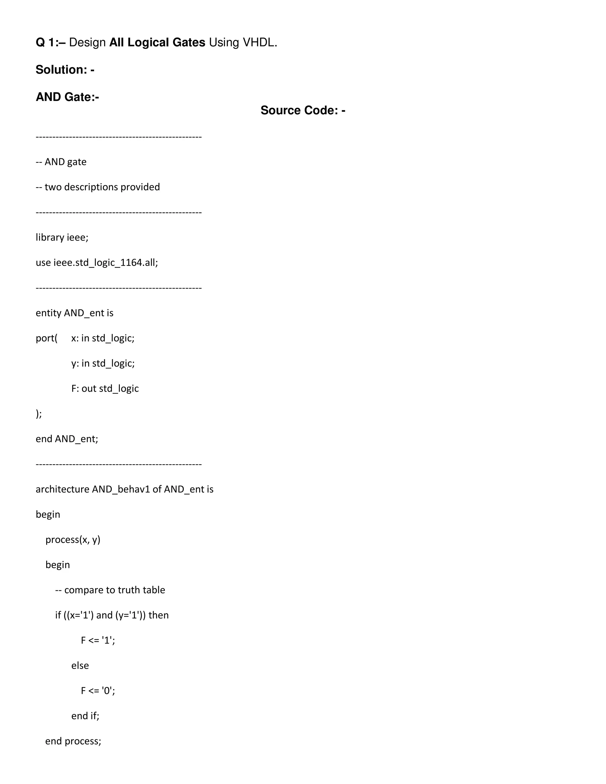
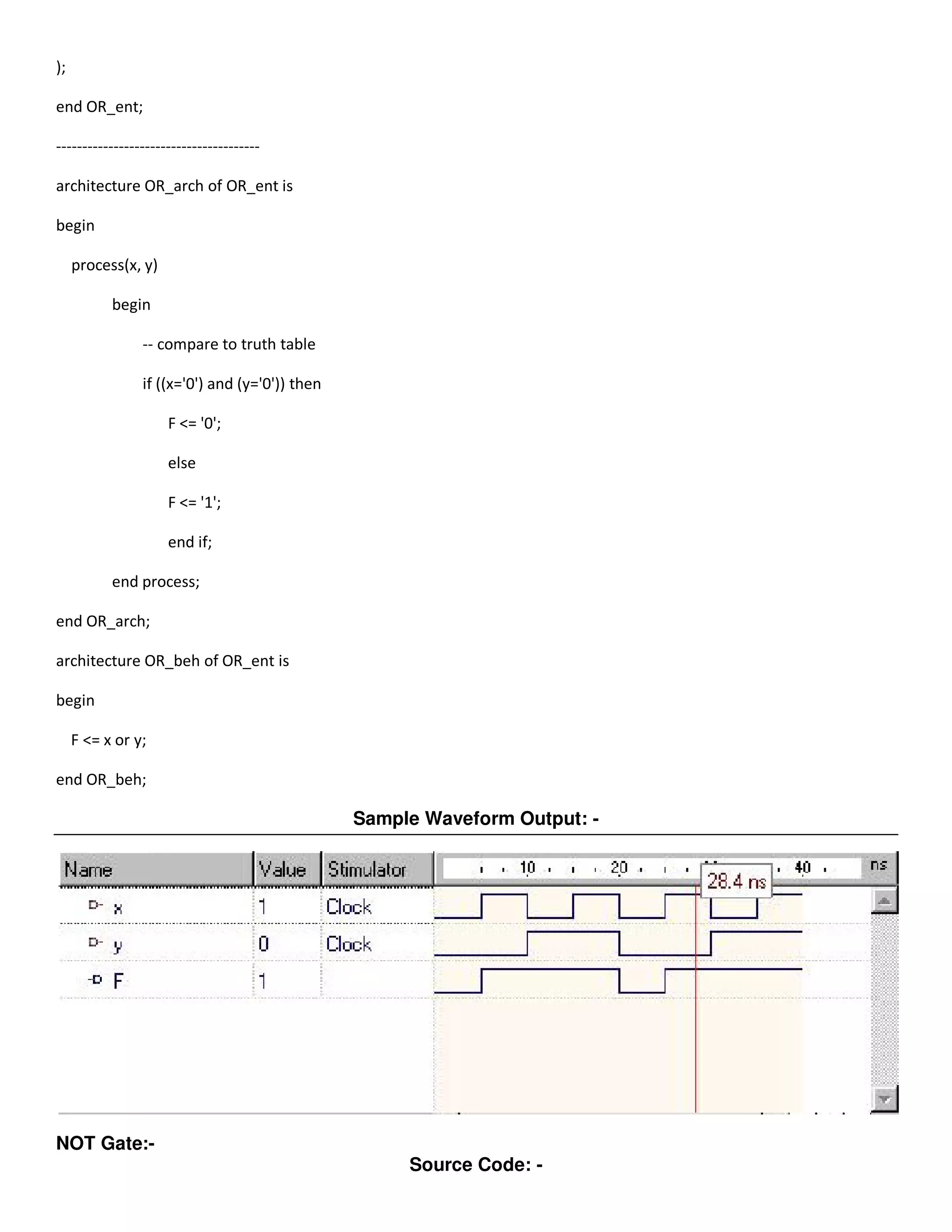
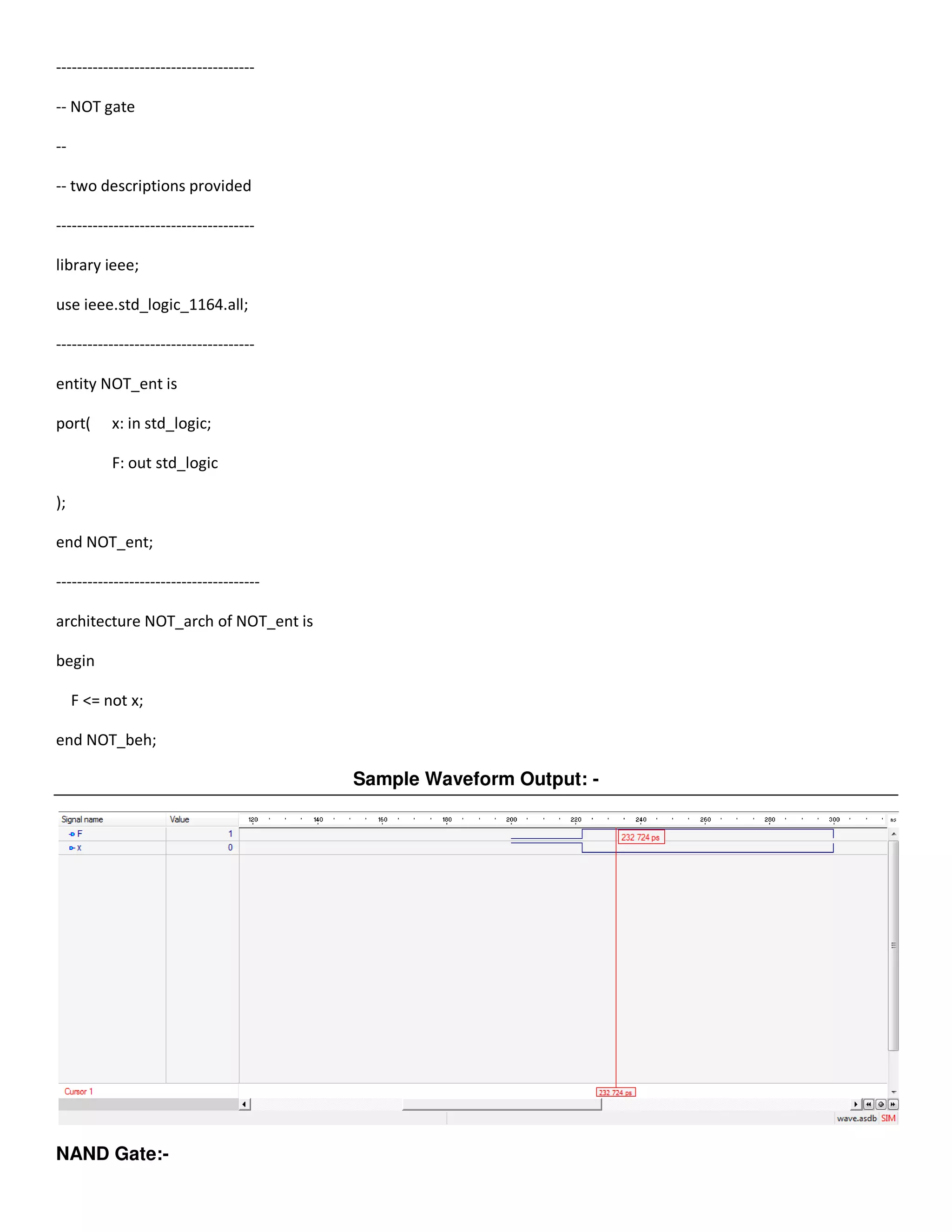
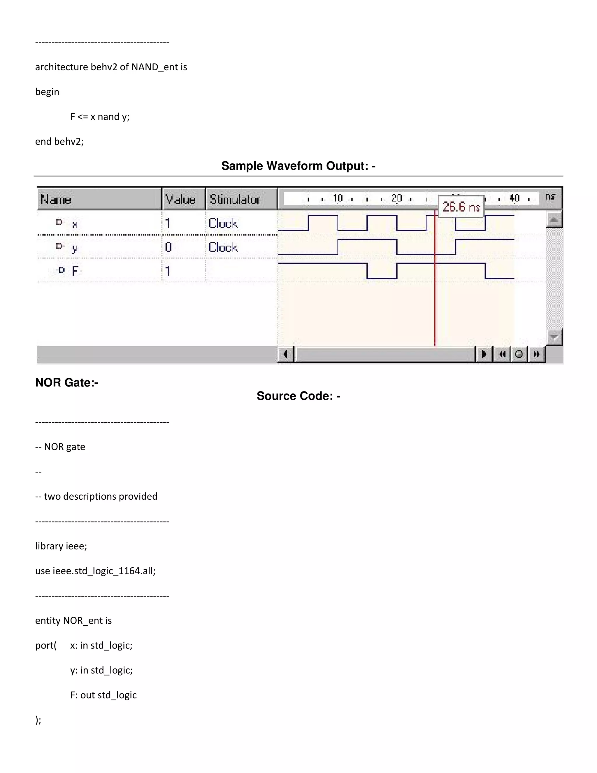
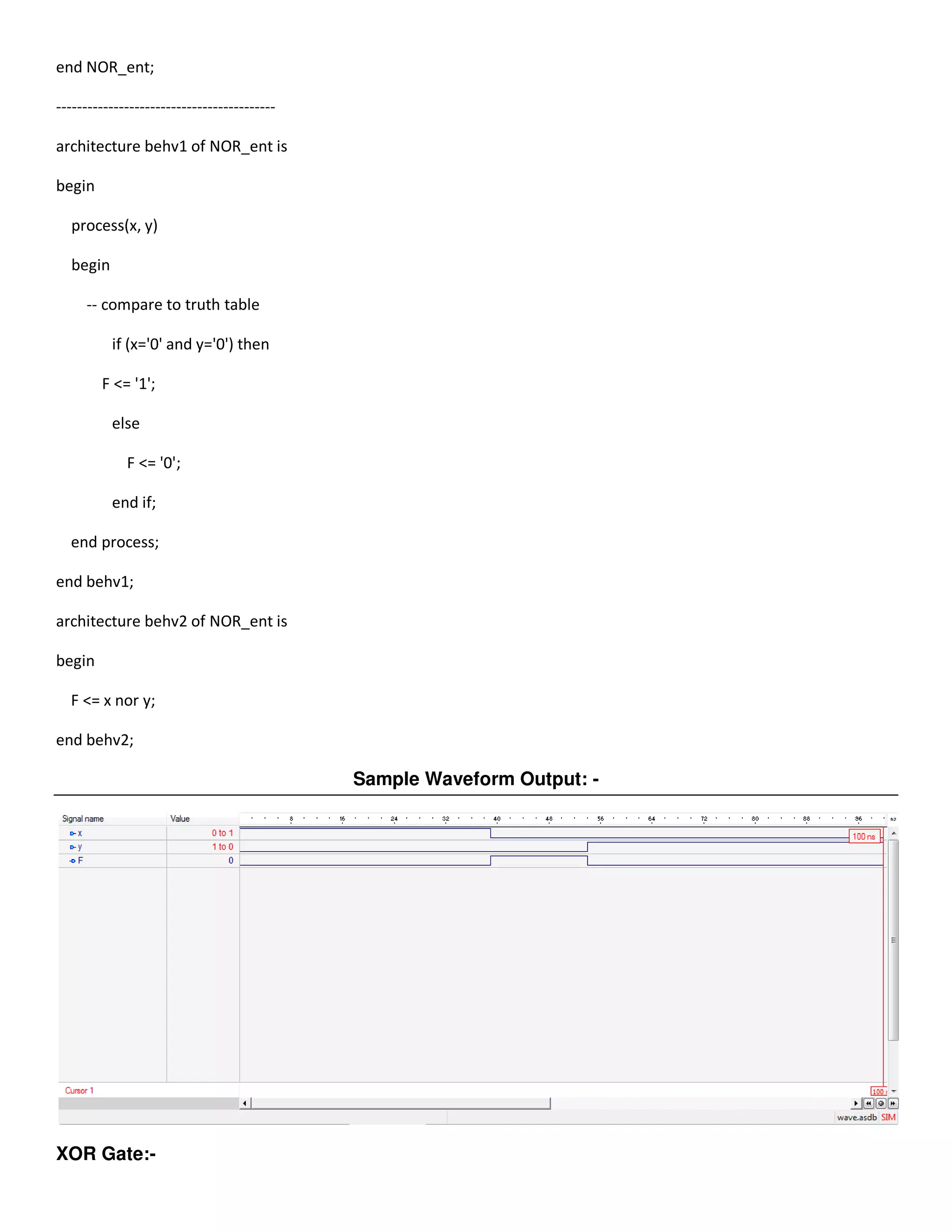
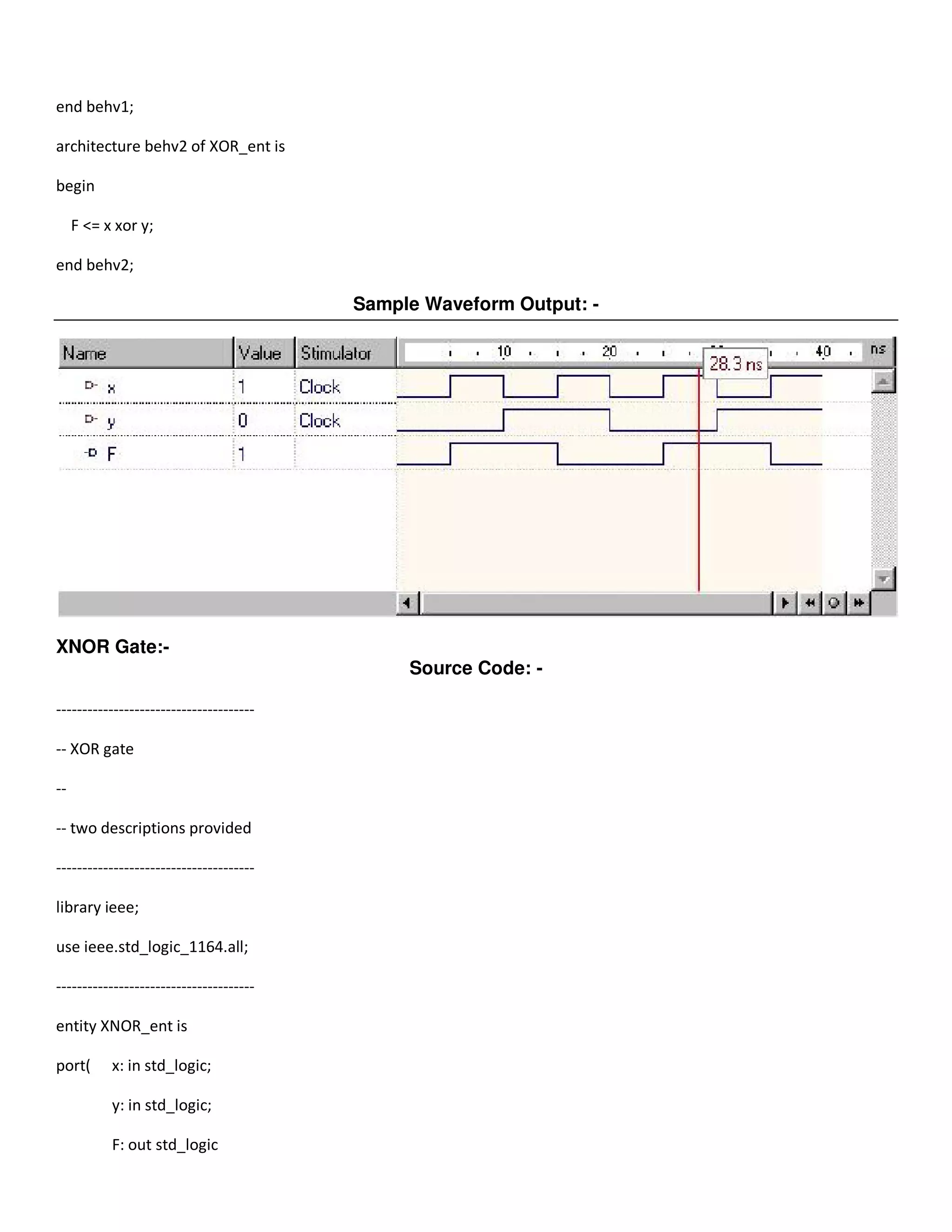
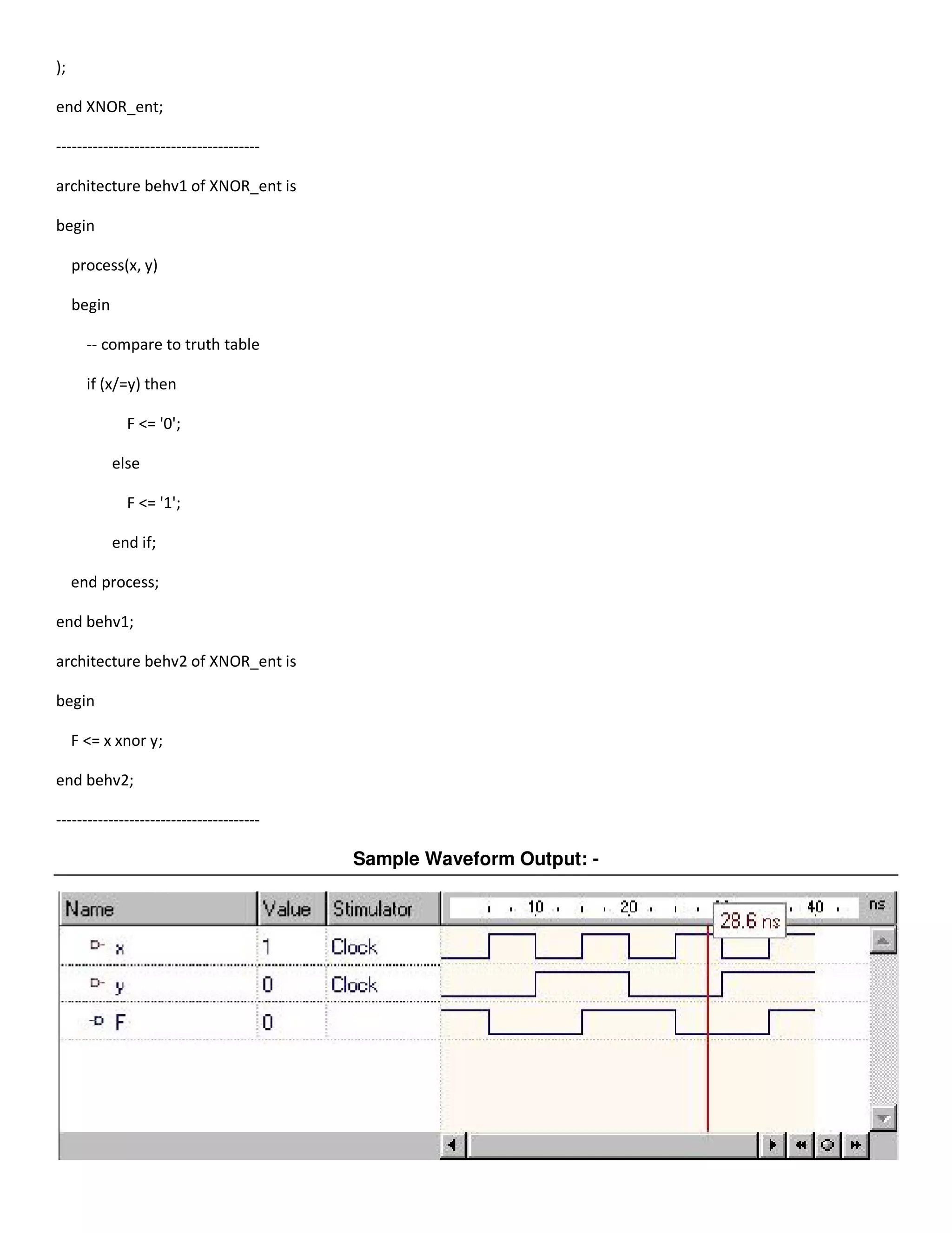
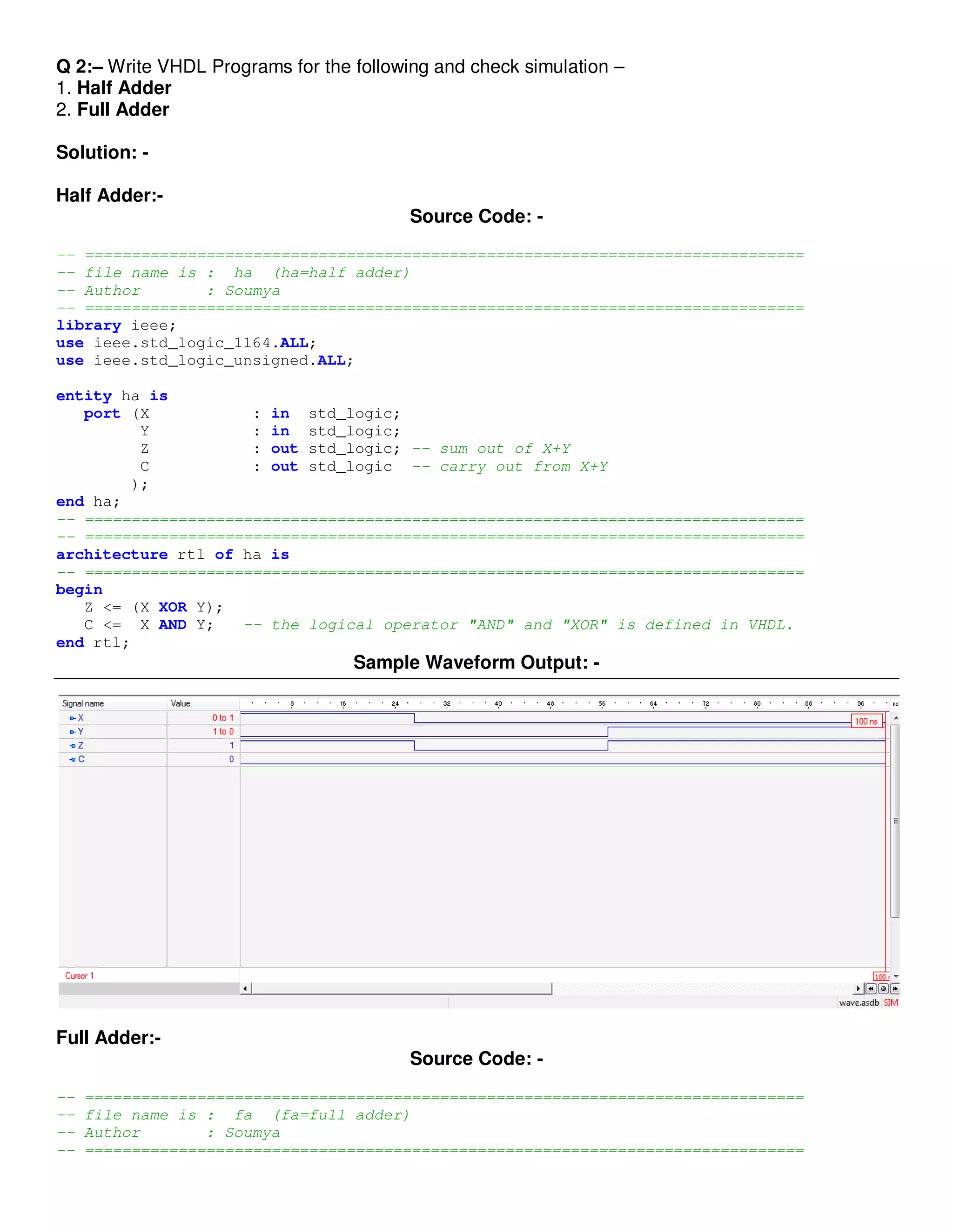
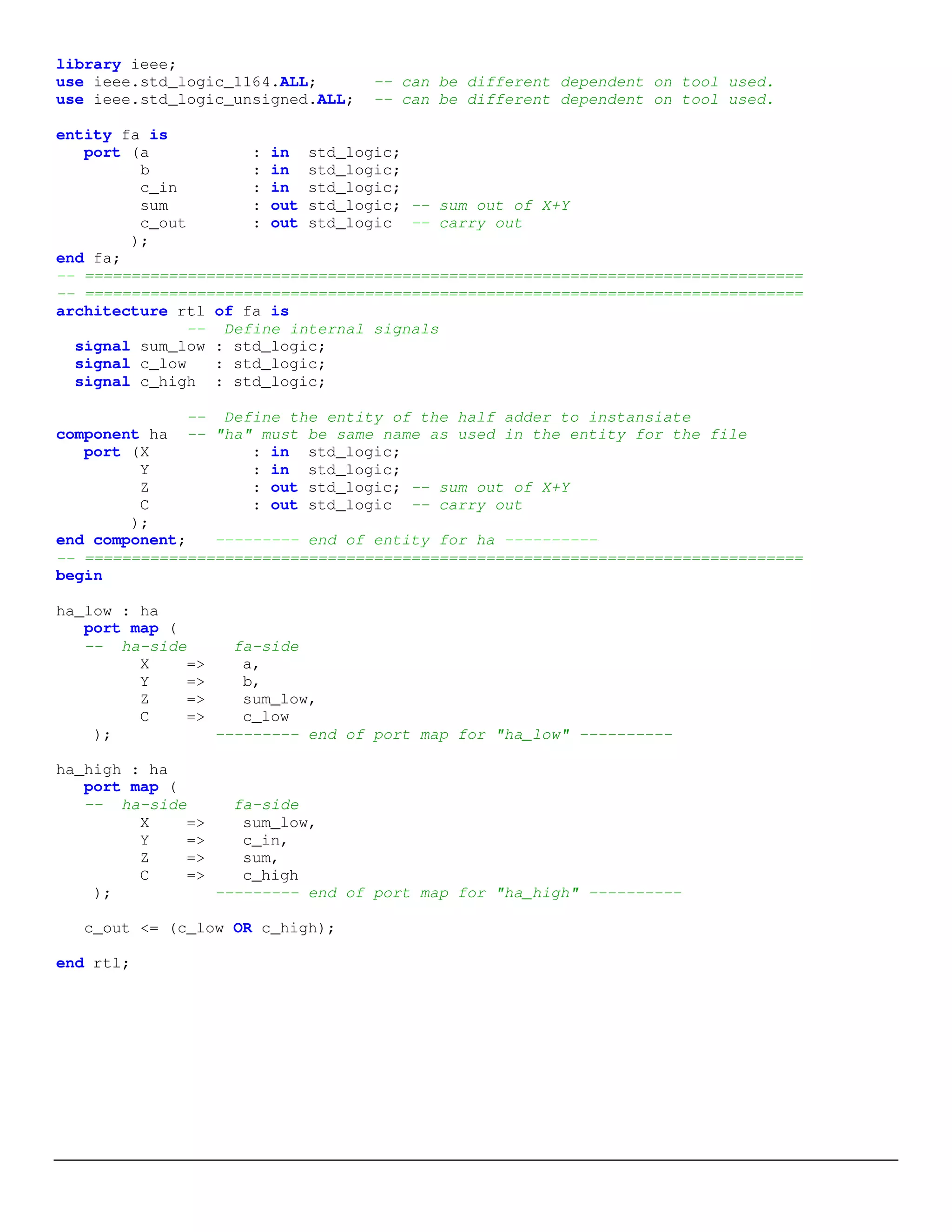
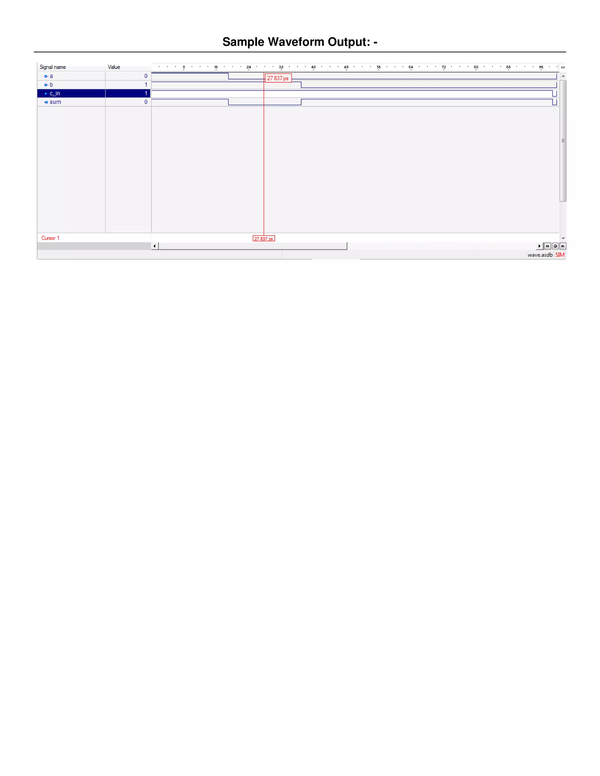
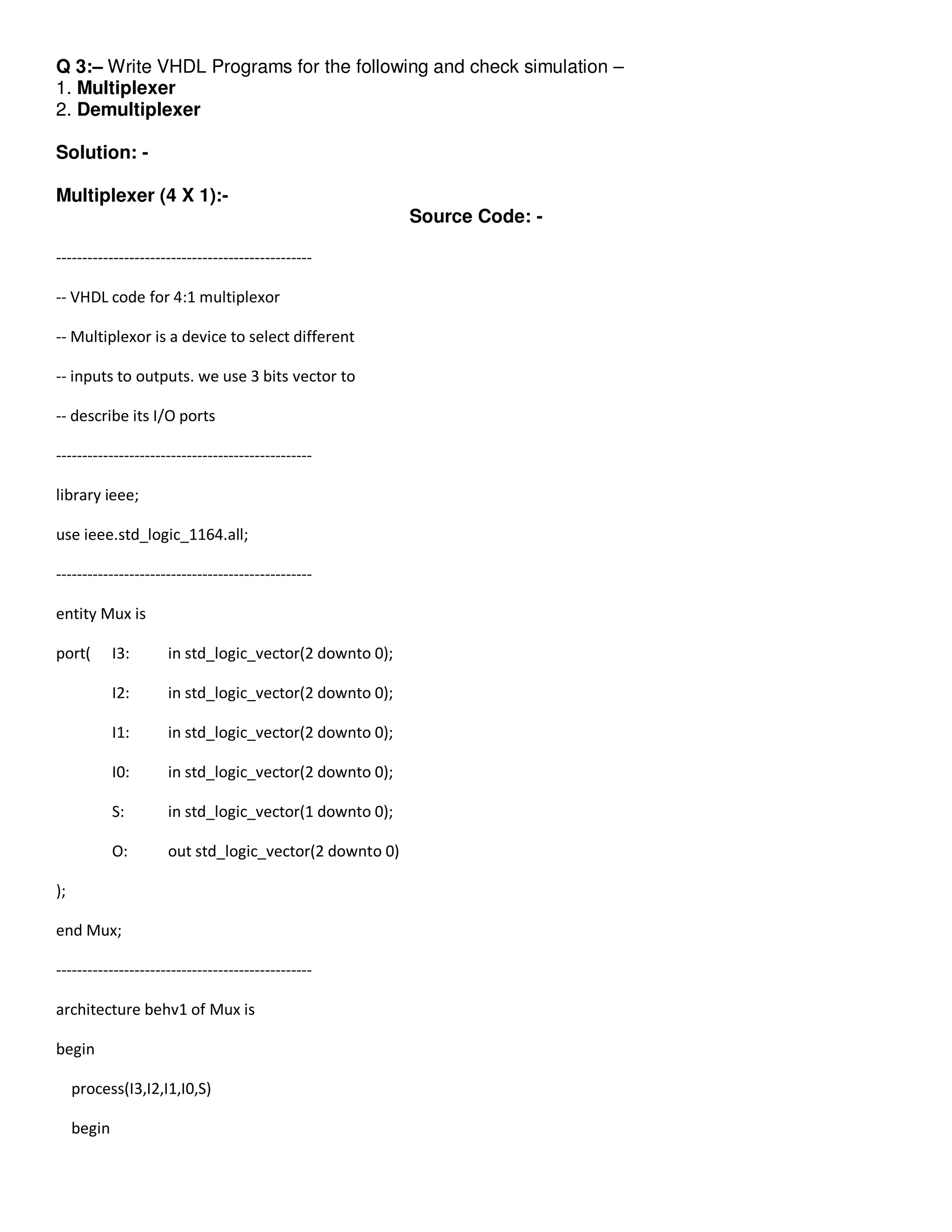
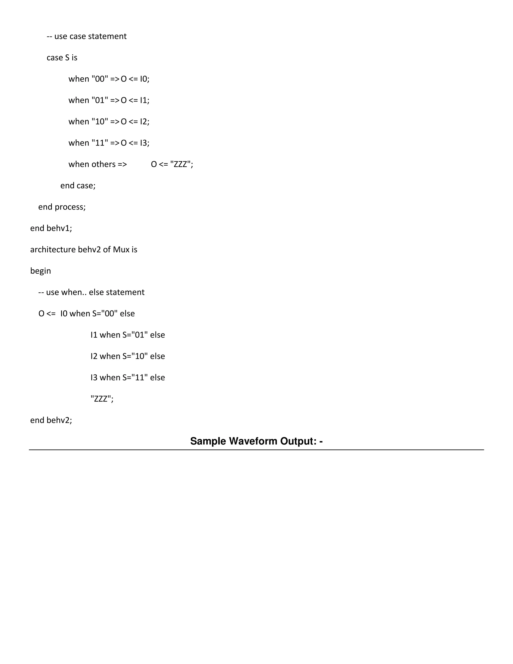
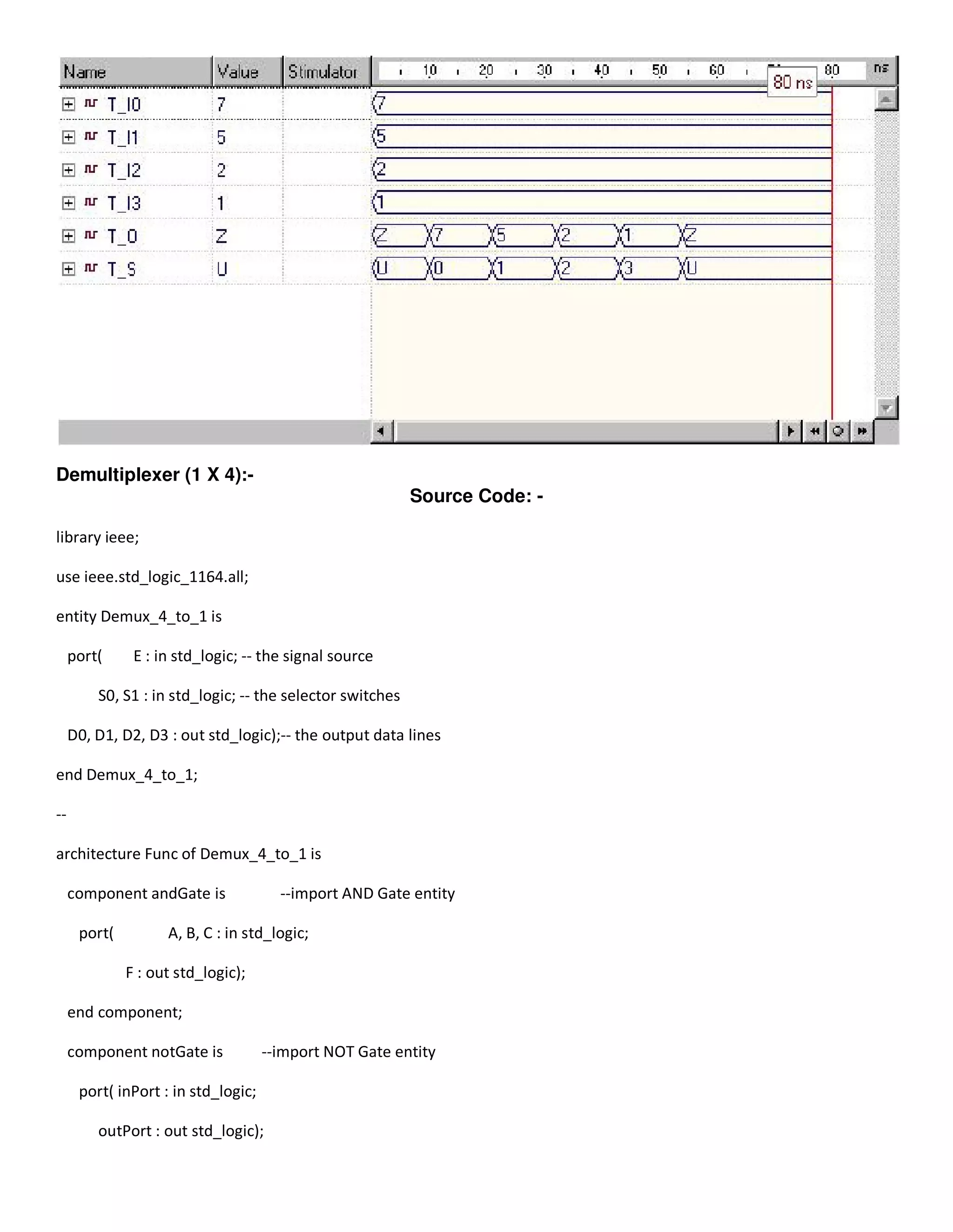
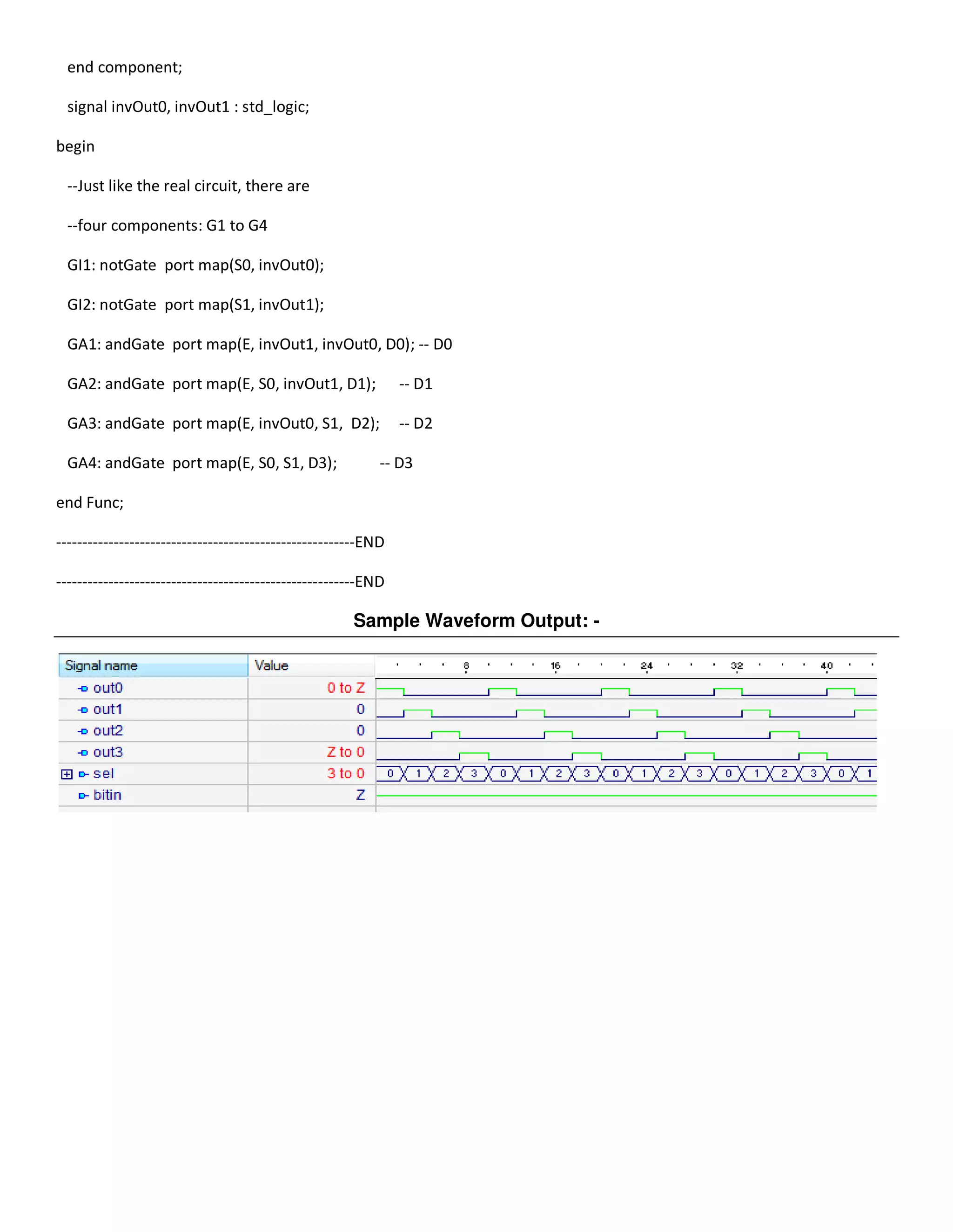
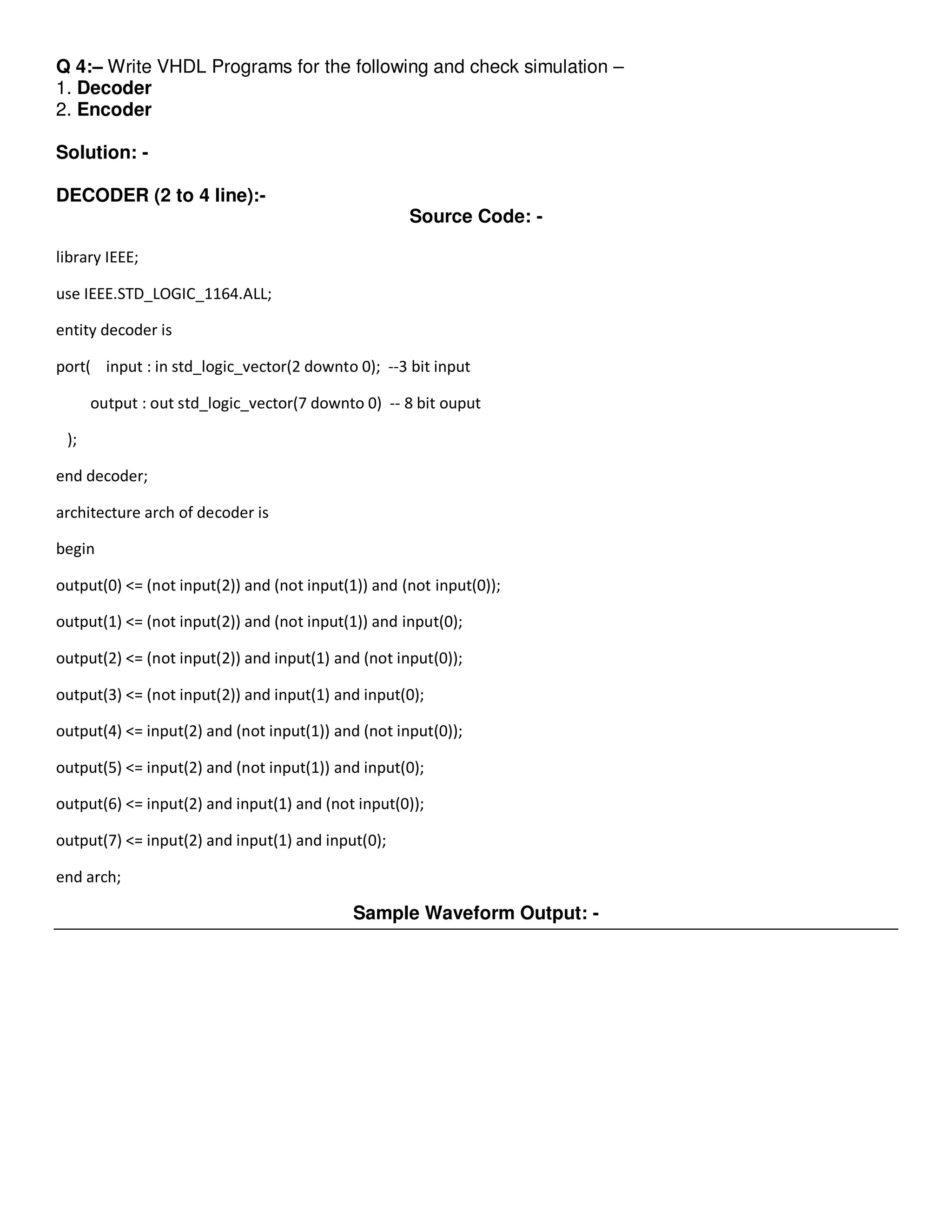
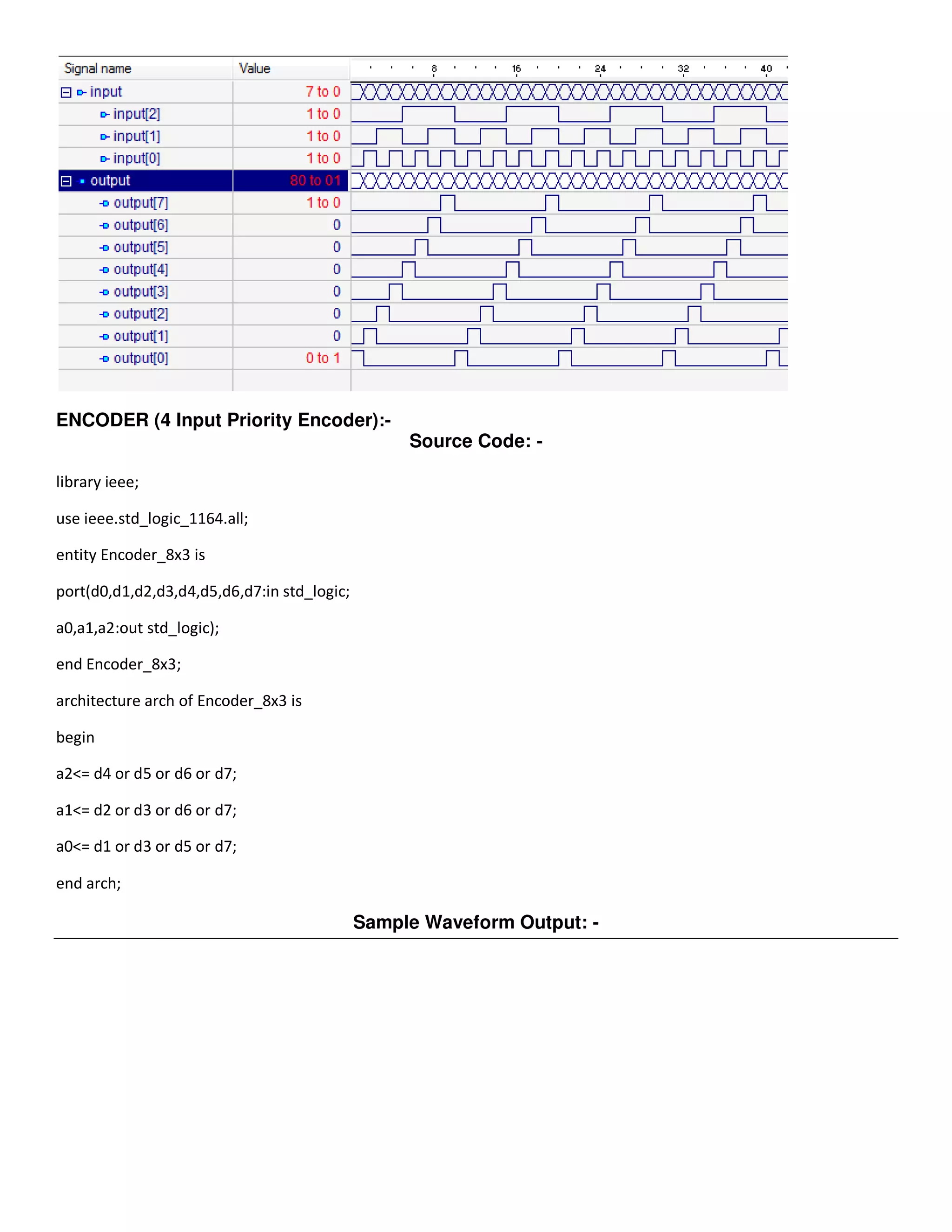
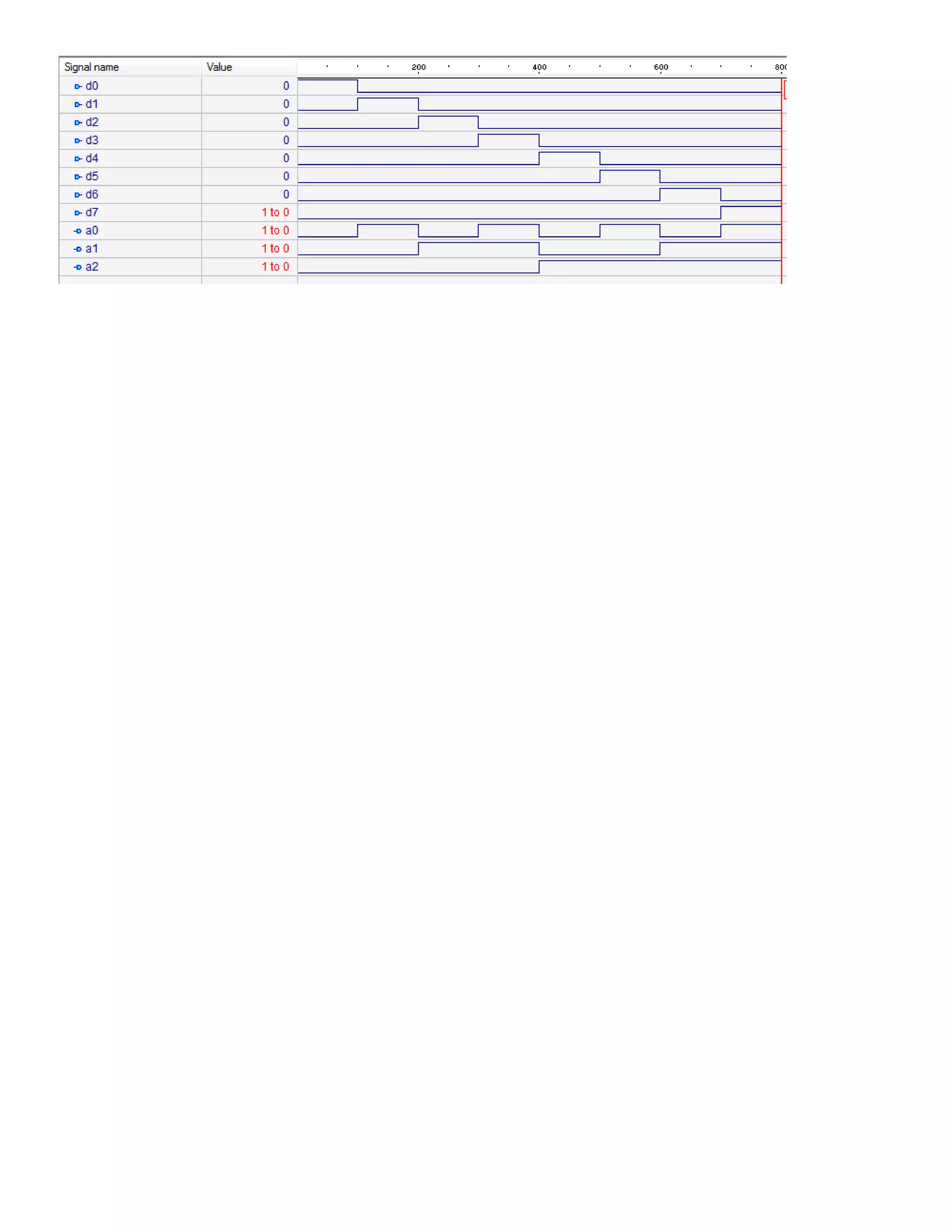
Q 1:– Design All Logical Gates Using VHDL. 
Solution: - 
AND Gate:- 
Source Code: - 
-------------------------------------------------- 
-- AND gate 
-- two descriptions provided 
-------------------------------------------------- 
library ieee; 
use ieee.std_logic_1164.all; 
-------------------------------------------------- 
entity AND_ent is 
port( x: in std_logic; 
y: in std_logic; 
F: out std_logic 
); 
end AND_ent; 
-------------------------------------------------- 
architecture AND_behav1 of AND_ent is 
begin 
process(x, y) 
begin 
-- compare to truth table 
if ((x='1') and (y='1')) then 
F <= '1'; 
else 
F <= '0'; 
end if; 
end process;
end behav1; 
architecture AND_behav2 of AND_ent is 
begin 
F <= x and y; 
end behav2; 
Sample Waveform Output: - 
OR Gate:- 
Source Code: - 
-------------------------------------- 
-- OR gate 
-- 
-- two descriptions provided 
-------------------------------------- 
library ieee; 
use ieee.std_logic_1164.all; 
-------------------------------------- 
entity OR_ent is 
port( x: in std_logic; 
y: in std_logic; 
F: out std_logic
); 
end OR_ent; 
--------------------------------------- 
architecture OR_arch of OR_ent is 
begin 
process(x, y) 
begin 
-- compare to truth table 
if ((x='0') and (y='0')) then 
F <= '0'; 
else 
F <= '1'; 
end if; 
end process; 
end OR_arch; 
architecture OR_beh of OR_ent is 
begin 
F <= x or y; 
end OR_beh; 
Sample Waveform Output: - 
NOT Gate:- 
Source Code: -
-------------------------------------- 
-- NOT gate 
-- 
-- two descriptions provided 
-------------------------------------- 
library ieee; 
use ieee.std_logic_1164.all; 
-------------------------------------- 
entity NOT_ent is 
port( x: in std_logic; 
F: out std_logic 
); 
end NOT_ent; 
--------------------------------------- 
architecture NOT_arch of NOT_ent is 
begin 
F <= not x; 
end NOT_beh; 
Sample Waveform Output: - 
NAND Gate:-
Source Code: - 
----------------------------------------- 
-- NAND gate 
-- 
-- two descriptions provided 
----------------------------------------- 
library ieee; 
use ieee.std_logic_1164.all; 
------------------------------------------ 
entity NAND_ent is 
port( x: in std_logic; 
y: in std_logic; 
F: out std_logic 
); 
end NAND_ent; 
------------------------------------------ 
architecture behv1 of NAND_ent is 
begin 
process(x, y) 
begin 
-- compare to truth table 
if (x='1' and y='1') then 
F <= '0'; 
else 
F <= '1'; 
end if; 
end process; 
end behv1;
----------------------------------------- 
architecture behv2 of NAND_ent is 
begin 
F <= x nand y; 
end behv2; 
Sample Waveform Output: - 
NOR Gate:- 
Source Code: - 
----------------------------------------- 
-- NOR gate 
-- 
-- two descriptions provided 
----------------------------------------- 
library ieee; 
use ieee.std_logic_1164.all; 
----------------------------------------- 
entity NOR_ent is 
port( x: in std_logic; 
y: in std_logic; 
F: out std_logic 
);
end NOR_ent; 
------------------------------------------ 
architecture behv1 of NOR_ent is 
begin 
process(x, y) 
begin 
-- compare to truth table 
if (x='0' and y='0') then 
F <= '1'; 
else 
F <= '0'; 
end if; 
end process; 
end behv1; 
architecture behv2 of NOR_ent is 
begin 
F <= x nor y; 
end behv2; 
Sample Waveform Output: - 
XOR Gate:-
Source Code: - 
-------------------------------------- 
-- XOR gate 
-- 
-- two descriptions provided 
-------------------------------------- 
library ieee; 
use ieee.std_logic_1164.all; 
-------------------------------------- 
entity XOR_ent is 
port( x: in std_logic; 
y: in std_logic; 
F: out std_logic 
); 
end XOR_ent; 
-------------------------------------- 
architecture behv1 of XOR_ent is 
begin 
process(x, y) 
begin 
-- compare to truth table 
if (x/=y) then 
F <= '1'; 
else 
F <= '0'; 
end if; 
end process;
end behv1; 
architecture behv2 of XOR_ent is 
begin 
F <= x xor y; 
end behv2; 
Sample Waveform Output: - 
XNOR Gate:- 
Source Code: - 
-------------------------------------- 
-- XOR gate 
-- 
-- two descriptions provided 
-------------------------------------- 
library ieee; 
use ieee.std_logic_1164.all; 
-------------------------------------- 
entity XNOR_ent is 
port( x: in std_logic; 
y: in std_logic; 
F: out std_logic
); 
end XNOR_ent; 
--------------------------------------- 
architecture behv1 of XNOR_ent is 
begin 
process(x, y) 
begin 
-- compare to truth table 
if (x/=y) then 
F <= '0'; 
else 
F <= '1'; 
end if; 
end process; 
end behv1; 
architecture behv2 of XNOR_ent is 
begin 
F <= x xnor y; 
end behv2; 
--------------------------------------- 
Sample Waveform Output: -
Q 2:– Write VHDL Programs for the following and check simulation – 
1. Half Adder 
2. Full Adder 
Solution: - 
Half Adder:- 
Source Code: - 
-- ============================================================================= 
-- file name is : ha (ha=half adder) 
-- Author : Soumya 
-- ============================================================================= 
library ieee; 
use ieee.std_logic_1164.ALL; 
use ieee.std_logic_unsigned.ALL; 
entity ha is 
port (X : in std_logic; 
Y : in std_logic; 
Z : out std_logic; -- sum out of X+Y 
C : out std_logic -- carry out from X+Y 
); 
end ha; 
-- ============================================================================= 
-- ============================================================================= 
architecture rtl of ha is 
-- ============================================================================= 
begin 
Z <= (X XOR Y); 
C <= X AND Y; -- the logical operator "AND" and "XOR" is defined in VHDL. 
end rtl; 
Sample Waveform Output: - 
Full Adder:- 
Source Code: - 
-- ============================================================================= 
-- file name is : fa (fa=full adder) 
-- Author : Soumya 
-- =============================================================================
library ieee; 
use ieee.std_logic_1164.ALL; -- can be different dependent on tool used. 
use ieee.std_logic_unsigned.ALL; -- can be different dependent on tool used. 
entity fa is 
port (a : in std_logic; 
b : in std_logic; 
c_in : in std_logic; 
sum : out std_logic; -- sum out of X+Y 
c_out : out std_logic -- carry out 
); 
end fa; 
-- ============================================================================= 
-- ============================================================================= 
architecture rtl of fa is 
-- Define internal signals 
signal sum_low : std_logic; 
signal c_low : std_logic; 
signal c_high : std_logic; 
-- Define the entity of the half adder to instansiate 
component ha -- "ha" must be same name as used in the entity for the file 
port (X : in std_logic; 
Y : in std_logic; 
Z : out std_logic; -- sum out of X+Y 
C : out std_logic -- carry out 
); 
end component; --------- end of entity for ha ---------- 
-- ============================================================================= 
begin 
ha_low : ha 
port map ( 
-- ha-side fa-side 
X => a, 
Y => b, 
Z => sum_low, 
C => c_low 
); --------- end of port map for "ha_low" ---------- 
ha_high : ha 
port map ( 
-- ha-side fa-side 
X => sum_low, 
Y => c_in, 
Z => sum, 
C => c_high 
); --------- end of port map for "ha_high" ---------- 
c_out <= (c_low OR c_high); 
end rtl;
Sample Waveform Output: -
Q 3:– Write VHDL Programs for the following and check simulation – 
1. Multiplexer 
2. Demultiplexer 
Solution: - 
Multiplexer (4 X 1):- 
Source Code: - 
------------------------------------------------- 
-- VHDL code for 4:1 multiplexor 
-- Multiplexor is a device to select different 
-- inputs to outputs. we use 3 bits vector to 
-- describe its I/O ports 
------------------------------------------------- 
library ieee; 
use ieee.std_logic_1164.all; 
------------------------------------------------- 
entity Mux is 
port( I3: in std_logic_vector(2 downto 0); 
I2: in std_logic_vector(2 downto 0); 
I1: in std_logic_vector(2 downto 0); 
I0: in std_logic_vector(2 downto 0); 
S: in std_logic_vector(1 downto 0); 
O: out std_logic_vector(2 downto 0) 
); 
end Mux; 
------------------------------------------------- 
architecture behv1 of Mux is 
begin 
process(I3,I2,I1,I0,S) 
begin
-- use case statement 
case S is 
when "00" => O <= I0; 
when "01" => O <= I1; 
when "10" => O <= I2; 
when "11" => O <= I3; 
when others => O <= "ZZZ"; 
end case; 
end process; 
end behv1; 
architecture behv2 of Mux is 
begin 
-- use when.. else statement 
O <= I0 when S="00" else 
I1 when S="01" else 
I2 when S="10" else 
I3 when S="11" else 
"ZZZ"; 
end behv2; 
Sample Waveform Output: -
Demultiplexer (1 X 4):- 
Source Code: - 
library ieee; 
use ieee.std_logic_1164.all; 
entity Demux_4_to_1 is 
port( E : in std_logic; -- the signal source 
S0, S1 : in std_logic; -- the selector switches 
D0, D1, D2, D3 : out std_logic);-- the output data lines 
end Demux_4_to_1; 
-- 
architecture Func of Demux_4_to_1 is 
component andGate is --import AND Gate entity 
port( A, B, C : in std_logic; 
F : out std_logic); 
end component; 
component notGate is --import NOT Gate entity 
port( inPort : in std_logic; 
outPort : out std_logic);
end component; 
signal invOut0, invOut1 : std_logic; 
begin 
--Just like the real circuit, there are 
--four components: G1 to G4 
GI1: notGate port map(S0, invOut0); 
GI2: notGate port map(S1, invOut1); 
GA1: andGate port map(E, invOut1, invOut0, D0); -- D0 
GA2: andGate port map(E, S0, invOut1, D1); -- D1 
GA3: andGate port map(E, invOut0, S1, D2); -- D2 
GA4: andGate port map(E, S0, S1, D3); -- D3 
end Func; 
---------------------------------------------------------END 
Sample Waveform Output: -
Q 4:– Write VHDL Programs for the following and check simulation – 
1. Decoder 
2. Encoder 
Solution: - 
DECODER (2 to 4 line):- 
Source Code: - 
library IEEE; 
use IEEE.STD_LOGIC_1164.ALL; 
entity decoder is 
port( input : in std_logic_vector(2 downto 0); --3 bit input 
output : out std_logic_vector(7 downto 0) -- 8 bit ouput 
); 
end decoder; 
architecture arch of decoder is 
begin 
output(0) <= (not input(2)) and (not input(1)) and (not input(0)); 
output(1) <= (not input(2)) and (not input(1)) and input(0); 
output(2) <= (not input(2)) and input(1) and (not input(0)); 
output(3) <= (not input(2)) and input(1) and input(0); 
output(4) <= input(2) and (not input(1)) and (not input(0)); 
output(5) <= input(2) and (not input(1)) and input(0); 
output(6) <= input(2) and input(1) and (not input(0)); 
output(7) <= input(2) and input(1) and input(0); 
end arch; 
Sample Waveform Output: -
ENCODER (4 Input Priority Encoder):- 
Source Code: - 
library ieee; 
use ieee.std_logic_1164.all; 
entity Encoder_8x3 is 
port(d0,d1,d2,d3,d4,d5,d6,d7:in std_logic; 
a0,a1,a2:out std_logic); 
end Encoder_8x3; 
architecture arch of Encoder_8x3 is 
begin 
a2<= d4 or d5 or d6 or d7; 
a1<= d2 or d3 or d6 or d7; 
a0<= d1 or d3 or d5 or d7; 
end arch; 
Sample Waveform Output: -
Q 5:– Write a VHDL Program for a Comparator and check the simulation. 
Solution: - 
COMPARATOR:- 
Source Code: - 
LIBRARY ieee ; 
USE ieee.std_logic_1164.all ; 
USE ieee.std_logic_arith.all ; 
ENTITY compare IS 
PORT ( A, B : IN SIGNED(3 DOWNTO 0) ; 
AeqB, AgtB, AltB : OUT STD_LOGIC ) ; 
END compare ; 
ARCHITECTURE Behavior OF compare IS 
BEGIN 
AeqB <= '1' WHEN A = B ELSE '0' ; 
AgtB <= '1' WHEN A > B ELSE '0' ; 
AltB <= '1' WHEN A < B ELSE '0' ; 
END Behavior ; 
Sample Waveform Output: -
Q 6:– Write a VHDL Program for a Code Convertor and check the simulation. 
Solution: - 
BCD to BINARY CODE CONVERTOR:- 
Source Code: - 
library IEEE; 
use IEEE.STD_LOGIC_1164.ALL; 
entity BCD2BIN is 
Port ( bcd : in STD_LOGIC_VECTOR (4 downto 0); 
binary : out STD_LOGIC_VECTOR (3 downto 0)); 
end BCD2BIN; 
architecture Behavioral of BCD2BIN is 
begin 
process (bcd) 
begin 
case bcd is 
when "00000" => binary <= "0000"; 
when "00001" => binary <= "0001"; 
when "00010" => binary <= "0010"; 
when "00011" => binary <= "0011"; 
when "00100" => binary <= "0100"; 
when "00101" => binary <= "0101"; 
when "00110" => binary <= "0110"; 
when "00111" => binary <= "0111"; 
when "01000" => binary <= "1000"; 
when "01001" => binary <= "1001"; 
when "10000" => binary <= "1010"; 
when "10001" => binary <= "1011"; 
when "10010" => binary <= "1100"; 
when "10011" => binary <= "1101"; 
when "10100" => binary <= "1110"; 
when "10101" => binary <= "1111";
when others => binary <= "XXXX"; 
end case; 
end process; 
end Behavioral; 
Sample Waveform Output: -
Q 7:– Write a VHDL Program for a Flip-Flop and check the simulation. 
Solution: - 
JK FLIP FLOP:- 
Source Code: - 
library IEEE; 
use IEEE.STD_LOGIC_1164.ALL; 
entity jk is 
Port ( J : in STD_LOGIC; 
K : in STD_LOGIC; 
clock : in STD_LOGIC; 
reset : in STD_LOGIC; 
Q : out STD_LOGIC; 
Qbar : out STD_LOGIC); 
end jk; 
architecture Behavioral of jk is 
signal state: std_logic; 
signal input: std_logic_vector(1 downto 0); 
begin 
input <= J & K; 
p: process(clock, reset) is 
begin 
if (reset='1') then 
state <= '0'; 
elsif (rising_edge(clock)) then 
case (input) is 
when "11" => 
state <= not state; 
when "10" => 
state <= '1'; 
when "01" => 
state <= '0';
when others => 
null; 
end case; 
end if; 
end process; 
Q <= state; 
Qbar <= not state; 
end Behavioral; 
Sample Waveform Output: -
Q 8:– Write a VHDL Program for a Counter and check the simulation. 
Solution: - 
N BIT COUNTER:- 
Source Code: - 
---------------------------------------------------- 
-- VHDL code for n-bit counter 
-- 
-- this is the behavior description of n-bit counter 
-- another way can be used is FSM model. 
---------------------------------------------------- 
library ieee ; 
use ieee.std_logic_1164.all; 
use ieee.std_logic_unsigned.all; 
---------------------------------------------------- 
entity counter is 
generic(n: natural :=2); 
port( clock: in std_logic; 
clear: in std_logic; 
count: in std_logic; 
Q: out std_logic_vector(n-1 downto 0) 
); 
end counter; 
---------------------------------------------------- 
architecture behv of counter is 
signal Pre_Q: std_logic_vector(n-1 downto 0); 
begin 
-- behavior describe the counter 
process(clock, count, clear) 
begin 
if clear = '1' then 
Pre_Q <= Pre_Q - Pre_Q; 
elsif (clock='1' and clock'event) then 
if count = '1' then 
Pre_Q <= Pre_Q + 1; 
end if; 
end if; 
end process; 
-- concurrent assignment statement 
Q <= Pre_Q; 
end behv; 
Sample Waveform Output: -
Q 9:– Write VHDL Programs for the following and check simulation – 
1. Register 
2. Shift Register 
Solution: - 
N-Bit Register:- 
Source Code: - 
--------------------------------------------------- 
-- n-bit Register (ESD book figure 2.6) 
-- 
-- KEY WORD: concurrent, generic and range 
--------------------------------------------------- 
library ieee ; 
use ieee.std_logic_1164.all; 
use ieee.std_logic_unsigned.all; 
--------------------------------------------------- 
entity reg is 
generic(n: natural :=2); 
port( I: in std_logic_vector(n-1 downto 0); 
clock: in std_logic; 
load: in std_logic; 
clear: in std_logic; 
Q: out std_logic_vector(n-1 downto 0) 
); 
end reg; 
---------------------------------------------------- 
architecture behv of reg is 
signal Q_tmp: std_logic_vector(n-1 downto 0); 
begin 
process(I, clock, load, clear) 
begin 
if clear = '0' then 
-- use 'range in signal assigment 
Q_tmp <= (Q_tmp'range => '0'); 
elsif (clock='1' and clock'event) then 
if load = '1' then 
Q_tmp <= I; 
end if; 
end if; 
end process;
-- concurrent statement 
Q <= Q_tmp; 
end behv; 
--------------------------------------------------- 
Sample Waveform Output: - 
3-Bit Shift Register:- 
Source Code: - 
--------------------------------------------------- 
-- 3-bit Shift-Register/Shifter 
-- 
-- reset is ignored according to the figure 
--------------------------------------------------- 
library ieee ; 
use ieee.std_logic_1164.all; 
--------------------------------------------------- 
entity shift_reg is 
port( I: in std_logic; 
clock: in std_logic; 
shift: in std_logic; 
Q: out std_logic 
); 
end shift_reg; 
--------------------------------------------------- 
architecture behv of shift_reg is 
-- initialize the declared signal 
signal S: std_logic_vector(2 downto 0):="111"; 
begin
process(I, clock, shift, S) 
begin 
-- everything happens upon the clock changing 
if clock'event and clock='1' then 
if shift = '1' then 
S <= I & S(2 downto 1); 
end if; 
end if; 
end process; 
-- concurrent assignment 
Q <= S(0); 
end behv; 
Sample Waveform Output: -
PRACTICAL FILE 
DDDDIIIIGGGGIIIITTTTAAAALLLL SSSSYYYYSSSSTTTTEEEEMMMM 
DDDDEEEESSSSIIIIGGGGNNNN LLLLAAAABBBB 
Softwares Used – 1. Xilinx 13.4 
2. ActiveHDL 7.2 SE 
Submitted To:- Submitted By:- 
Mr. Manoj Ahlawat Soumya S. Behera 
Asst. Professor 1826 
6th Semester, CSE 
UIET, Mdu, Rohtak

Dsdlab 120528004329-phpapp01

  • 1.
    Q 1:– DesignAll Logical Gates Using VHDL. Solution: - AND Gate:- Source Code: - -------------------------------------------------- -- AND gate -- two descriptions provided -------------------------------------------------- library ieee; use ieee.std_logic_1164.all; -------------------------------------------------- entity AND_ent is port( x: in std_logic; y: in std_logic; F: out std_logic ); end AND_ent; -------------------------------------------------- architecture AND_behav1 of AND_ent is begin process(x, y) begin -- compare to truth table if ((x='1') and (y='1')) then F <= '1'; else F <= '0'; end if; end process;
  • 2.
    end behav1; architectureAND_behav2 of AND_ent is begin F <= x and y; end behav2; Sample Waveform Output: - OR Gate:- Source Code: - -------------------------------------- -- OR gate -- -- two descriptions provided -------------------------------------- library ieee; use ieee.std_logic_1164.all; -------------------------------------- entity OR_ent is port( x: in std_logic; y: in std_logic; F: out std_logic
  • 3.
    ); end OR_ent; --------------------------------------- architecture OR_arch of OR_ent is begin process(x, y) begin -- compare to truth table if ((x='0') and (y='0')) then F <= '0'; else F <= '1'; end if; end process; end OR_arch; architecture OR_beh of OR_ent is begin F <= x or y; end OR_beh; Sample Waveform Output: - NOT Gate:- Source Code: -
  • 4.
    -------------------------------------- -- NOTgate -- -- two descriptions provided -------------------------------------- library ieee; use ieee.std_logic_1164.all; -------------------------------------- entity NOT_ent is port( x: in std_logic; F: out std_logic ); end NOT_ent; --------------------------------------- architecture NOT_arch of NOT_ent is begin F <= not x; end NOT_beh; Sample Waveform Output: - NAND Gate:-
  • 5.
    Source Code: - ----------------------------------------- -- NAND gate -- -- two descriptions provided ----------------------------------------- library ieee; use ieee.std_logic_1164.all; ------------------------------------------ entity NAND_ent is port( x: in std_logic; y: in std_logic; F: out std_logic ); end NAND_ent; ------------------------------------------ architecture behv1 of NAND_ent is begin process(x, y) begin -- compare to truth table if (x='1' and y='1') then F <= '0'; else F <= '1'; end if; end process; end behv1;
  • 6.
    ----------------------------------------- architecture behv2of NAND_ent is begin F <= x nand y; end behv2; Sample Waveform Output: - NOR Gate:- Source Code: - ----------------------------------------- -- NOR gate -- -- two descriptions provided ----------------------------------------- library ieee; use ieee.std_logic_1164.all; ----------------------------------------- entity NOR_ent is port( x: in std_logic; y: in std_logic; F: out std_logic );
  • 7.
    end NOR_ent; ------------------------------------------ architecture behv1 of NOR_ent is begin process(x, y) begin -- compare to truth table if (x='0' and y='0') then F <= '1'; else F <= '0'; end if; end process; end behv1; architecture behv2 of NOR_ent is begin F <= x nor y; end behv2; Sample Waveform Output: - XOR Gate:-
  • 8.
    Source Code: - -------------------------------------- -- XOR gate -- -- two descriptions provided -------------------------------------- library ieee; use ieee.std_logic_1164.all; -------------------------------------- entity XOR_ent is port( x: in std_logic; y: in std_logic; F: out std_logic ); end XOR_ent; -------------------------------------- architecture behv1 of XOR_ent is begin process(x, y) begin -- compare to truth table if (x/=y) then F <= '1'; else F <= '0'; end if; end process;
  • 9.
    end behv1; architecturebehv2 of XOR_ent is begin F <= x xor y; end behv2; Sample Waveform Output: - XNOR Gate:- Source Code: - -------------------------------------- -- XOR gate -- -- two descriptions provided -------------------------------------- library ieee; use ieee.std_logic_1164.all; -------------------------------------- entity XNOR_ent is port( x: in std_logic; y: in std_logic; F: out std_logic
  • 10.
    ); end XNOR_ent; --------------------------------------- architecture behv1 of XNOR_ent is begin process(x, y) begin -- compare to truth table if (x/=y) then F <= '0'; else F <= '1'; end if; end process; end behv1; architecture behv2 of XNOR_ent is begin F <= x xnor y; end behv2; --------------------------------------- Sample Waveform Output: -
  • 11.
    Q 2:– WriteVHDL Programs for the following and check simulation – 1. Half Adder 2. Full Adder Solution: - Half Adder:- Source Code: - -- ============================================================================= -- file name is : ha (ha=half adder) -- Author : Soumya -- ============================================================================= library ieee; use ieee.std_logic_1164.ALL; use ieee.std_logic_unsigned.ALL; entity ha is port (X : in std_logic; Y : in std_logic; Z : out std_logic; -- sum out of X+Y C : out std_logic -- carry out from X+Y ); end ha; -- ============================================================================= -- ============================================================================= architecture rtl of ha is -- ============================================================================= begin Z <= (X XOR Y); C <= X AND Y; -- the logical operator "AND" and "XOR" is defined in VHDL. end rtl; Sample Waveform Output: - Full Adder:- Source Code: - -- ============================================================================= -- file name is : fa (fa=full adder) -- Author : Soumya -- =============================================================================
  • 12.
    library ieee; useieee.std_logic_1164.ALL; -- can be different dependent on tool used. use ieee.std_logic_unsigned.ALL; -- can be different dependent on tool used. entity fa is port (a : in std_logic; b : in std_logic; c_in : in std_logic; sum : out std_logic; -- sum out of X+Y c_out : out std_logic -- carry out ); end fa; -- ============================================================================= -- ============================================================================= architecture rtl of fa is -- Define internal signals signal sum_low : std_logic; signal c_low : std_logic; signal c_high : std_logic; -- Define the entity of the half adder to instansiate component ha -- "ha" must be same name as used in the entity for the file port (X : in std_logic; Y : in std_logic; Z : out std_logic; -- sum out of X+Y C : out std_logic -- carry out ); end component; --------- end of entity for ha ---------- -- ============================================================================= begin ha_low : ha port map ( -- ha-side fa-side X => a, Y => b, Z => sum_low, C => c_low ); --------- end of port map for "ha_low" ---------- ha_high : ha port map ( -- ha-side fa-side X => sum_low, Y => c_in, Z => sum, C => c_high ); --------- end of port map for "ha_high" ---------- c_out <= (c_low OR c_high); end rtl;
  • 13.
  • 14.
    Q 3:– WriteVHDL Programs for the following and check simulation – 1. Multiplexer 2. Demultiplexer Solution: - Multiplexer (4 X 1):- Source Code: - ------------------------------------------------- -- VHDL code for 4:1 multiplexor -- Multiplexor is a device to select different -- inputs to outputs. we use 3 bits vector to -- describe its I/O ports ------------------------------------------------- library ieee; use ieee.std_logic_1164.all; ------------------------------------------------- entity Mux is port( I3: in std_logic_vector(2 downto 0); I2: in std_logic_vector(2 downto 0); I1: in std_logic_vector(2 downto 0); I0: in std_logic_vector(2 downto 0); S: in std_logic_vector(1 downto 0); O: out std_logic_vector(2 downto 0) ); end Mux; ------------------------------------------------- architecture behv1 of Mux is begin process(I3,I2,I1,I0,S) begin
  • 15.
    -- use casestatement case S is when "00" => O <= I0; when "01" => O <= I1; when "10" => O <= I2; when "11" => O <= I3; when others => O <= "ZZZ"; end case; end process; end behv1; architecture behv2 of Mux is begin -- use when.. else statement O <= I0 when S="00" else I1 when S="01" else I2 when S="10" else I3 when S="11" else "ZZZ"; end behv2; Sample Waveform Output: -
  • 16.
    Demultiplexer (1 X4):- Source Code: - library ieee; use ieee.std_logic_1164.all; entity Demux_4_to_1 is port( E : in std_logic; -- the signal source S0, S1 : in std_logic; -- the selector switches D0, D1, D2, D3 : out std_logic);-- the output data lines end Demux_4_to_1; -- architecture Func of Demux_4_to_1 is component andGate is --import AND Gate entity port( A, B, C : in std_logic; F : out std_logic); end component; component notGate is --import NOT Gate entity port( inPort : in std_logic; outPort : out std_logic);
  • 17.
    end component; signalinvOut0, invOut1 : std_logic; begin --Just like the real circuit, there are --four components: G1 to G4 GI1: notGate port map(S0, invOut0); GI2: notGate port map(S1, invOut1); GA1: andGate port map(E, invOut1, invOut0, D0); -- D0 GA2: andGate port map(E, S0, invOut1, D1); -- D1 GA3: andGate port map(E, invOut0, S1, D2); -- D2 GA4: andGate port map(E, S0, S1, D3); -- D3 end Func; ---------------------------------------------------------END ---------------------------------------------------------END Sample Waveform Output: -
  • 18.
    Q 4:– WriteVHDL Programs for the following and check simulation – 1. Decoder 2. Encoder Solution: - DECODER (2 to 4 line):- Source Code: - library IEEE; use IEEE.STD_LOGIC_1164.ALL; entity decoder is port( input : in std_logic_vector(2 downto 0); --3 bit input output : out std_logic_vector(7 downto 0) -- 8 bit ouput ); end decoder; architecture arch of decoder is begin output(0) <= (not input(2)) and (not input(1)) and (not input(0)); output(1) <= (not input(2)) and (not input(1)) and input(0); output(2) <= (not input(2)) and input(1) and (not input(0)); output(3) <= (not input(2)) and input(1) and input(0); output(4) <= input(2) and (not input(1)) and (not input(0)); output(5) <= input(2) and (not input(1)) and input(0); output(6) <= input(2) and input(1) and (not input(0)); output(7) <= input(2) and input(1) and input(0); end arch; Sample Waveform Output: -
  • 19.
    ENCODER (4 InputPriority Encoder):- Source Code: - library ieee; use ieee.std_logic_1164.all; entity Encoder_8x3 is port(d0,d1,d2,d3,d4,d5,d6,d7:in std_logic; a0,a1,a2:out std_logic); end Encoder_8x3; architecture arch of Encoder_8x3 is begin a2<= d4 or d5 or d6 or d7; a1<= d2 or d3 or d6 or d7; a0<= d1 or d3 or d5 or d7; end arch; Sample Waveform Output: -
  • 21.
    Q 5:– Writea VHDL Program for a Comparator and check the simulation. Solution: - COMPARATOR:- Source Code: - LIBRARY ieee ; USE ieee.std_logic_1164.all ; USE ieee.std_logic_arith.all ; ENTITY compare IS PORT ( A, B : IN SIGNED(3 DOWNTO 0) ; AeqB, AgtB, AltB : OUT STD_LOGIC ) ; END compare ; ARCHITECTURE Behavior OF compare IS BEGIN AeqB <= '1' WHEN A = B ELSE '0' ; AgtB <= '1' WHEN A > B ELSE '0' ; AltB <= '1' WHEN A < B ELSE '0' ; END Behavior ; Sample Waveform Output: -
  • 22.
    Q 6:– Writea VHDL Program for a Code Convertor and check the simulation. Solution: - BCD to BINARY CODE CONVERTOR:- Source Code: - library IEEE; use IEEE.STD_LOGIC_1164.ALL; entity BCD2BIN is Port ( bcd : in STD_LOGIC_VECTOR (4 downto 0); binary : out STD_LOGIC_VECTOR (3 downto 0)); end BCD2BIN; architecture Behavioral of BCD2BIN is begin process (bcd) begin case bcd is when "00000" => binary <= "0000"; when "00001" => binary <= "0001"; when "00010" => binary <= "0010"; when "00011" => binary <= "0011"; when "00100" => binary <= "0100"; when "00101" => binary <= "0101"; when "00110" => binary <= "0110"; when "00111" => binary <= "0111"; when "01000" => binary <= "1000"; when "01001" => binary <= "1001"; when "10000" => binary <= "1010"; when "10001" => binary <= "1011"; when "10010" => binary <= "1100"; when "10011" => binary <= "1101"; when "10100" => binary <= "1110"; when "10101" => binary <= "1111";
  • 23.
    when others =>binary <= "XXXX"; end case; end process; end Behavioral; Sample Waveform Output: -
  • 24.
    Q 7:– Writea VHDL Program for a Flip-Flop and check the simulation. Solution: - JK FLIP FLOP:- Source Code: - library IEEE; use IEEE.STD_LOGIC_1164.ALL; entity jk is Port ( J : in STD_LOGIC; K : in STD_LOGIC; clock : in STD_LOGIC; reset : in STD_LOGIC; Q : out STD_LOGIC; Qbar : out STD_LOGIC); end jk; architecture Behavioral of jk is signal state: std_logic; signal input: std_logic_vector(1 downto 0); begin input <= J & K; p: process(clock, reset) is begin if (reset='1') then state <= '0'; elsif (rising_edge(clock)) then case (input) is when "11" => state <= not state; when "10" => state <= '1'; when "01" => state <= '0';
  • 25.
    when others => null; end case; end if; end process; Q <= state; Qbar <= not state; end Behavioral; Sample Waveform Output: -
  • 26.
    Q 8:– Writea VHDL Program for a Counter and check the simulation. Solution: - N BIT COUNTER:- Source Code: - ---------------------------------------------------- -- VHDL code for n-bit counter -- -- this is the behavior description of n-bit counter -- another way can be used is FSM model. ---------------------------------------------------- library ieee ; use ieee.std_logic_1164.all; use ieee.std_logic_unsigned.all; ---------------------------------------------------- entity counter is generic(n: natural :=2); port( clock: in std_logic; clear: in std_logic; count: in std_logic; Q: out std_logic_vector(n-1 downto 0) ); end counter; ---------------------------------------------------- architecture behv of counter is signal Pre_Q: std_logic_vector(n-1 downto 0); begin -- behavior describe the counter process(clock, count, clear) begin if clear = '1' then Pre_Q <= Pre_Q - Pre_Q; elsif (clock='1' and clock'event) then if count = '1' then Pre_Q <= Pre_Q + 1; end if; end if; end process; -- concurrent assignment statement Q <= Pre_Q; end behv; Sample Waveform Output: -
  • 28.
    Q 9:– WriteVHDL Programs for the following and check simulation – 1. Register 2. Shift Register Solution: - N-Bit Register:- Source Code: - --------------------------------------------------- -- n-bit Register (ESD book figure 2.6) -- -- KEY WORD: concurrent, generic and range --------------------------------------------------- library ieee ; use ieee.std_logic_1164.all; use ieee.std_logic_unsigned.all; --------------------------------------------------- entity reg is generic(n: natural :=2); port( I: in std_logic_vector(n-1 downto 0); clock: in std_logic; load: in std_logic; clear: in std_logic; Q: out std_logic_vector(n-1 downto 0) ); end reg; ---------------------------------------------------- architecture behv of reg is signal Q_tmp: std_logic_vector(n-1 downto 0); begin process(I, clock, load, clear) begin if clear = '0' then -- use 'range in signal assigment Q_tmp <= (Q_tmp'range => '0'); elsif (clock='1' and clock'event) then if load = '1' then Q_tmp <= I; end if; end if; end process;
  • 29.
    -- concurrent statement Q <= Q_tmp; end behv; --------------------------------------------------- Sample Waveform Output: - 3-Bit Shift Register:- Source Code: - --------------------------------------------------- -- 3-bit Shift-Register/Shifter -- -- reset is ignored according to the figure --------------------------------------------------- library ieee ; use ieee.std_logic_1164.all; --------------------------------------------------- entity shift_reg is port( I: in std_logic; clock: in std_logic; shift: in std_logic; Q: out std_logic ); end shift_reg; --------------------------------------------------- architecture behv of shift_reg is -- initialize the declared signal signal S: std_logic_vector(2 downto 0):="111"; begin
  • 30.
    process(I, clock, shift,S) begin -- everything happens upon the clock changing if clock'event and clock='1' then if shift = '1' then S <= I & S(2 downto 1); end if; end if; end process; -- concurrent assignment Q <= S(0); end behv; Sample Waveform Output: -
  • 31.
    PRACTICAL FILE DDDDIIIIGGGGIIIITTTTAAAALLLLSSSSYYYYSSSSTTTTEEEEMMMM DDDDEEEESSSSIIIIGGGGNNNN LLLLAAAABBBB Softwares Used – 1. Xilinx 13.4 2. ActiveHDL 7.2 SE Submitted To:- Submitted By:- Mr. Manoj Ahlawat Soumya S. Behera Asst. Professor 1826 6th Semester, CSE UIET, Mdu, Rohtak