Download to read offline
![International
OPEN ACCESS Journal
Of Modern Engineering Research (IJMER)
| IJMER | ISSN: 2249–6645 | www.ijmer.com | Vol. 4 | Iss.11| Nov. 2014 | 20|
Improving the Stability of Cascaded DC Power Supply System by
Adaptive Active Capacitor Converter
B. Prudvi Kumar Reddy1, B. Amruth Kumar Reddy2
1M.Tech Student, Dr.K.V.S.R College of Technology, Kurnool, Andhra Pradesh
2 EEE Department, .K.V.S.R College of Technology, Kurnool,, Andhra Pradesh
I. INTRODUCTION
The dc division energy orbit (DEO) has been used widely in such applications as space stations,
aircraft, communication systems, industrial autonomous production lines and defense electronic power systems
for the last 20 years [1]–[5], due to its flexile system configuration, high-efficiency energy conversion, and high-density
power delivery capability .One of the dc DEO’S attractive characteristics is modularity design[6], in
which each Subsystem is first designed individually as a module, and then all subsystems are integrated to form
a dc DEO. The modularization characteristic of dc DEO cuts down the system’s development cycles and costs
effectively. In a dc DPS, there are various ways to connect the subsystems, among which, a typical connection
style is cascaded Converters.
Fig. 1. Cascaded power supply system.
Abstract: When all links are changes in the cascade is the corner of the shape in the dc division
energy orbit (DEO). When resistances are intermission betwixt one by one stylish changes in that
would possibly end up so the cascaded orbits are unsteady. They are antecedent we can place in a
nearer to the useful in the cascaded orbit can be got in compelled to vary the supply they have load
changes in the internal structure of the same regions in the electrical device they can be opposed in
a quality of the characteristic of dc DEO. Throughout the Associate in nursing adaptation active
device in the (AACC) we can know another determined in the cascaded orbit. Therefore the AACC
was connected by side by side in the cascaded orbit’s they can mediate in between the carries and
completely a requirement of a notice then they carries the voltage with none modification in this
subsystems. Then it will have a stylish to the customary have basic units to measuring in the dc
DEO. When the AACC is additionally a similar bus device to cut back the output resistance of the
supply device, therefore averting in a interiority have their load changes in the input resistance, of
the cascaded orbit have their solutions then they becomes constant. We have important carrier
device it will computing in the AACC adaptation in line with they have output energy to the
cascaded orbit, they have energy vesting in the AACC that’s way they will reduced and therefore
they have a lot of energy in a reacting to the orbit so it is a best in the orbit of a submissive device.
What's many, since no capacitance have a requirement among an AACC, when the cascaded orbits
have their quantity of it slowly it will extend in time. They have activity fundamental truth to stop
their magnificence thought in the AACC are mentioned throughout of this project, it can have four
thousand eight hundred and zero watts cascaded orbit was contain a strive of process to move in a
full-bridge changes they can be styli shed and evaluated. So when the simulation solutions have to
clear the performance of the arrangement of AACC.
Index Terms: Active capacitor converter, adaptive control, cascaded System, modularization,
stability.](https://image.slidesharecdn.com/d0401104-2031-141209050400-conversion-gate01/85/Improving-the-Stability-of-Cascaded-DC-Power-Supply-System-by-Adaptive-Active-Capacitor-Converter-1-320.jpg)
![Improving the Stability of Cascaded DC Power Supply System by Adaptive Active Capacitor Converter
| IJMER | ISSN: 2249–6645 | www.ijmer.com | Vol. 4 | Iss.11| Nov. 2014 | 21|
The cascaded system may have stability problem due to the interaction between the subsystems, even though each subsystem is individually well designed to be stable on its own [7]–[12].This problem was first analyzed by idle brook [13]. It was shown that for the typical cascaded system shown in Fig. 1, the ratio of the source converter’s output impedance Zo and the load converter’s input impedance Zin, Zo /Zin , can be equivalently represented as the loop gain of the cascaded system. It was also pointed out that if both the ource converter and the load converter are stable individually, and Zo is less than Zin in the entire frequency ranges, the stability of the cascaded system will be guaranteed. This is the so-called Middle brook criterion. Subsequently, various impedance criteria aiming at a more accurate and practical prediction of the subsystem interaction had been developed in the last two decades [14]–[19].Solutions for solving the instability problem have been proposed and can be broadly classified into two types: passive [20]–[22] and active [23]–[29] methods. Passive methods employ passive components, such as resistors, capacitors, and inductors, to improve system stability. A resistive load was added to modify load dynamic characteristics in [20], thereby improving system stability. Both RC and RL dampers were introduced to minimize the output impedance peak of the source converter in [21] and [22], thus ensuring Zo be less than Zin in the entire frequency ranges. The passive methods incur significant power dissipation. Active methods for stabilizing the system are based on modifying the control of the source converter [23]–[26]and/or load converter [27], or adding a power buffer between the source and load subsystems [28], [29]. The former approach, however, is usually complex in implementation and sometimes proposed conflicting with other control objectives. For the latter approach, the power buffer is connected in series in-between the subsystems, and would affect the impedance interaction during the transient that may not be acceptable in some applications. All the aforementioned solutions need to change the internal structure, including the main circuit and/or control circuit, of the dc DEO’s subsystems, leading to redesign of the subsystems that have already been modularly designed. This contradicts with the objective of the modularity design of dc DPS and increases the system’s development cycles. This paper introduces an adaptive active capacitor converter (AACC) connected in parallel with the remediate bus of the cascaded system. The AACC is equivalent to an adaptive bus capacitor varied with the cascaded system’s output power; which reduces the output impedance of the source converter to avoid interacting with load converter’s input impedance. As a result, the cascaded system becomes stable. The AACC only needs to detect the intermediate bus voltage without changing anything of the existing subsystems; hence, it serves as a standard stabilizer for dc DEO. Meanwhile, the equivalent capacitor of the AACC is adaptive, ensuring a minimal additional power loss and a better dynamic response of the system than that using a passive capacitor. Furthermore, as no electrolytic capacitor is required in the AACC, the lifetime of the cascaded system is prolonged. This paper first analyzes the impedance characteristics and instability problem of the cascaded system in Section II, and presents the concept, operating principle, ad control strategy of AACC in Section III. The design procedure and a design ample of AACC are given in Section IV. Section V shows he experimental results that verify the effectiveness of the proposed method. Finally, Section VI concludes this paper
II. Impedance Characteristics And Instability Problem Of Cascaded System
A. Review of Subsystem’s Impedance Characteristics and Cause of Instability For cascaded systems, the impedance characteristics of subsystems and the cause of instability have been studied extensively during the last two decades [30]–[35]. Some general conclusions are summarized as follows: 1) Impedance characteristic of Zo : Zo is the source converter’s output impedance independent of its load resistor. As shown in the dotted line of Fig. 2, Zo is similar to the output impedance of an LC filter. Iff < fc S, Zo presents the characteristic of an inductor; and if f > fc S, Zo presents the characteristic of source converter’s output filter capacitor. Here, fc S is the cutoff frequency of the source converter’s voltage loop. Note that Zo ’s peak value ,Zo peak, appears at fc S and is inversely proportional to source converter’s output filter capacitor [30]. 2) Impedance characteristic of Zin : In Fig. 2, the solid line Represents Zin that is the input impedance of load converter Operating in continuous current mode (CCM). Iff < fc L, Zin behaves as a negative resistor, whose value equals to −V 2 bus/Po [31], where Vbus is the intermediate bus voltage and Po is the load converter’s output power](https://image.slidesharecdn.com/d0401104-2031-141209050400-conversion-gate01/85/Improving-the-Stability-of-Cascaded-DC-Power-Supply-System-by-Adaptive-Active-Capacitor-Converter-2-320.jpg)
![Improving the Stability of Cascaded DC Power Supply System by Adaptive Active Capacitor Converter
| IJMER | ISSN: 2249–6645 | www.ijmer.com | Vol. 4 | Iss.11| Nov. 2014 | 22|
Fig. 2. Impedance interaction of the cascaded system.
Fig. 3. Cascaded system with additional intermediate bus capacitor
Fig. 4. Equivalent model of Zo with additional intermediate bus capacitor
and if f > fc L, Zin behaves as an inductor. Here, fc Lis the cutoff frequency of the load converter’s voltage loop.
Note that when f < fc L , the magnitude of Zin is inversely proportional to Po [32].
3) Cause of instability: In a cascaded system, as shown in
Figs. 1 and 2, if Zo is intersected with Zin and fc S is less than fc L , the cascaded system will be unstable [33].In
this case, the oscillation frequency is fc S that is unaffected by system’s power [34].
The above analysis indicates that Zo is not affected by Po , and when f < fc L , the magnitude of Zin is inversely
proportional to Po . Thus, the cascaded system is most likely to be unstable at full load because Zin is minimal
and easily intersected with Zoat this condition. Note that the above conclusions are general and applicable to all
dc–dc converters.
B. Solving the Instability Problem by Adding Intermediate Bus Capacitor
There is nothing more desirable than a total separation between Zo and Zin to ensure that the cascaded
system is stable. Since |Zo peak| is inversely proportional to source converter’s output filter capacitor [30], one
intuitive way is to reduce the source converter’ output impedance by adding an intermediate bus capacitor Cbus
to the cascaded system, as shown in Fig. 3.Here, Cbus can be treated as an additional output filter capacitor of
the source converter, and the equivalent LC output impedance model of source converter with Cbus is given in
Fig. 4. In Fig. 4, Le S is the equivalent filter’s inductor, Ce S is the equivalent filter’s capacitor, Rle S is the
parasitic resistor of
Fig. 5. Topology of the AACC introduced into cascaded system](https://image.slidesharecdn.com/d0401104-2031-141209050400-conversion-gate01/85/Improving-the-Stability-of-Cascaded-DC-Power-Supply-System-by-Adaptive-Active-Capacitor-Converter-3-320.jpg)
![Improving the Stability of Cascaded DC Power Supply System by Adaptive Active Capacitor Converter
| IJMER | ISSN: 2249–6645 | www.ijmer.com | Vol. 4 | Iss.11| Nov. 2014 | 23|
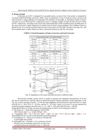
Le S , and Rce S is the equivalent series resistor (ESR) of Ce S that can be measured from Fig. 2. Also, Ce S, Le S , and Rle S are expressed in (1)–(3), respectively Ce S =1/ 2πRce S fesr S (1) Le S =1/(2πfc S )2 Ce S (2) Rle S = Le S/Ce S · |Zo peak|− Rce S (3) where fesr S is the zero caused by the ESR of Ce S . According to (1)–(3), the peak value of Zo in Fig. 4 is derived as |Zo peak| = Le S/(Ce S + Cbus) (Rle S + Rce S ) . (4) Thus, in order to ensure that Zo < Zin in the entire frequency ranges, |Zo peak| must satisfy |Zo peak| ≤ V 2bus/Po . (5) From (4) and (5), the required value of Cbus can be obtained as Cbus ≥ Le SPo/V 2bus (Rle S + Rce S) − Ce S. (6) According to (6), the required Cbus increases with the increase of Po , so, if a capacitor is employed, its value must be selected by (6) at full load. However, a larger Cbus results in a smaller bandwidth of the source converter that is already modularly designed, leading to a poor dynamic performance [35].Since the required Cbus is relatively large, it inevitably adopts electrolytic capacitor, indicating a significant reduction of the lifetime [36]. In fact, the value of Cbus could be selected adaptively according to Po , as shown in (6), which keeps Cbus at its minimal required value for different loads. In this way, the cascaded system does not only ensure stable, but also achieves a better dynamic response.
III. Topology And Control Of The Proposed AACC
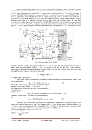
A. Topology of AACC The adaptively varying Cbus mentioned in Section II can be Emulated by a converter, as shown in the dashed block in Fig. 5.The converter is referred to as AACC. The AACC is composed of switches Qa1 and Qa2 , inductor La , and capacitor Ca. It is connected to the intermediate bus of the cascaded system. By controlling La ’s current appropriately, the terminal characteristic at the bus side of AACC will present an adaptively varying Cbus that ensures the stability of the cascaded system and improves the dynamic response. The AACC is also suitable for the cascaded system with multiple load converters. In this case, the AACC has the same operation principle with the system of Fig. 5, which just makes the source converter’s output impedance lower than the total input impedance of the multiple load converters [17]. This paper analyzes the case shown in Fig. 5, but the conclusion applies to the system with multiple load converters. B. Control of AACC Since the function of AACC is to emulate the adaptive Cbus, the current of La, ia , should be controlled as ia (t) = Cbus(dvbus/dt) . (7) According to (6) and (7), it can be known that ia varies with Po . Considering Po can be reflected by the oscillation rippleof vbus, Δvbus [37], ia could be controlled by Δvbus, whose control cicuit is realized by a simple analog circuit, as shown inFig. 6. The control circuit for ia would only need to detect vbus without changing any part of the existing subsystems. Thus, the AACC can be designed as a standard module for dc DPS.As shown in Fig. 6, vbus first goes through a differential circuit (sub circuit A) to get the form of ia ref (dvbus/dt), defined as v1 . Meanwhile, Δvbus is extracted from vbus by the filter comprising C2 and R5 , and then it is sent to the rectifier circuit and a peak value detection circuit, producing Δvbus’s magnitudev2 . Then, v2 is compared with the preset allowable voltage ripple ΔVbus allow, and the error is amplified by amplifier A4. The output of A4, v3 , is the magnitude of ia ref . Therefore, ia refis adaptively varied by Po: a large Po brings a larger Δvbus, leading to a larger ia ref , which means a larger equivalent Cbus of AACC; and on the contrary, a smaller Po gives a smaller equivalent Cbus of AACC. Effectively, if Po is small enough, Δvbus will be less than ΔVbus allow and ia ref will be zero, which means that Cbus is no longer required at this time. Multiplying v1 with v3 by the multiplier, and the output,](https://image.slidesharecdn.com/d0401104-2031-141209050400-conversion-gate01/85/Improving-the-Stability-of-Cascaded-DC-Power-Supply-System-by-Adaptive-Active-Capacitor-Converter-4-320.jpg)
![Improving the Stability of Cascaded DC Power Supply System by Adaptive Active Capacitor Converter
| IJMER | ISSN: 2249–6645 | www.ijmer.com | Vol. 4 | Iss.11| Nov. 2014 | 25|
(11)
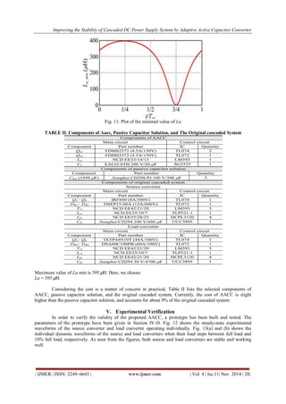
Fig. 7. Waveforms of instantaneous input power, inductor current, and output filter capacitor voltage of the
AACC.
Here, ΔEa (t) can also be expressed as
[ΔEa (t)=1/2CaV]_a^2(t) -1/2CaV]_(a min) ^2
where Va min is the minimum voltage of the capacitor Ca .
Putting (12) in (11) gives
[1/2Ca [V〗_a^2(t) - V_ (a min) ^2] =2 VbusCbus ΔVbus_allow Sin2 (ω/2t +π/4)
(13)
From (13), we have
Va(t) = (14)
Substitution of t = 5Tos /4 into (14), the maximum voltage of
the capacitor Ca can be derived as
Va max = (15)
The average voltage of Ca can be approximated as
Vabc = (Va min + Va max)/2
= Va min + (16)
Fig. 8. Plots of V a max, V a min, and V adc as functions of C a .](https://image.slidesharecdn.com/d0401104-2031-141209050400-conversion-gate01/85/Improving-the-Stability-of-Cascaded-DC-Power-Supply-System-by-Adaptive-Active-Capacitor-Converter-6-320.jpg)


![Improving the Stability of Cascaded DC Power Supply System by Adaptive Active Capacitor Converter
| IJMER | ISSN: 2249–6645 | www.ijmer.com | Vol. 4 | Iss.11| Nov. 2014 | 30|
the bigger importance capacitance. Once they can moves in the cascaded system have a very small value, when the AACC can supply less power in the produce have smaller importance capacitance. Once there is no moves in a cascaded system they have a periodic voltage among in a permutable to the opportunity, of the AACC are going to be stop working. They can have employment in the AACC doesn’t solely make sure the undisturbed conditions in a cascaded system, however additionally unpleasant situation in the important loss. When the energy has a lot of reactions in the cascaded system have additionally then see a better change in the employment of a yielding capacitance. Moreover, there is an electrolytic employed during AACC of the incorporates a hopeful effect in a organized period. They will tally in the present technique, the projected convertor solely has they discover the cascaded system to the bus voltage while not dynamic something in the present subsystems, thus they will be a stylish to the customary can be measuring in the dc DPS. Then AACC will been ascertain carefully see the power values that is four thousand eight hundred zero watts and we can see different voltage ratings in the cascaded system. After we can see the exacta output results of the experimental in the validity of the analysis. REFERENCES [1] F. Blaabjerg, A. Consoli, J. A. Ferreira, and J. D. van Wyk, ―The future of electronic power processing and conversion,‖ IEEE Trans. Power Electron., vol. 20, no. 3, pp. 715–720, May 2005. [2] J. D. van Wyk and F. C. Lee, ―Power electronics technology—Status and future,‖ in Proc. CPES, 1999, pp. 61–70. [3] K. T. Kornegay, ―Design issues in power electronic building block (PEBB) system integration,‖ in Proc. IEEE VLSI, Apr. 1998, pp. 48–52. [4] T. Ericsen, ―Power electronic building blocks—A systematic approach to power electronics,‖ in Proc. IEEE Power Eng. Soc. Summer Meeting, 2000, pp. 1216–1218. [5] D. Boroyevich, I. Cvetkovi c, D. Dong, R. Burgos, F. Wang, and F. C. Lee, ―Future electronic power distribution systems—A contemplative view,‖ in Proc. IEEE OPTIM, May 2010, pp. 1369–1380. [6] S. Luo, ―A review of distributed power systems part I: DC distributed power system,‖ IEEE Aerosp. Electron. Syst. Mag., vol. 20, no. 8, pp. 5–16, Aug. 2005. [7] L. R. Lewis, B. H. Cho, F. C. Lee, and B. A. Carpenter, ―Modeling, Analysis and design of distributed power systems,‖ in Proc. IEEE PESC, Jun. 1989, pp. 152–159. [8] G. A. Franz, G. W. Ludwig, and R. L. Steigerwald, ―Modeling and simulation of distributed power systems,‖ in Proc. IEEE PESC, 1990, pp. 606–610. [9] S. Schulz, B. H. Cho, and F. C. Lee, ―Design considerations for a distributed power system,‖ in Proc. IEEE PESC, 1990, pp. 611–617. [10] B. H. Cho and B. Choi, ―Analysis and design of multi-stage distributed power systems,‖ in Proc. Int. Telecomm. Energy Conf., Kyoto, Japan, Nov. 1991, pp. 220–226. [11] A. Emadi, ―Modeling of power electronic loads in ac distribution systems using the generalized state-space averaging method,‖ IEEE Trans. Ind. Electron., vol. 51, no. 5, pp. 995–1000, Oct. 2004. [12] A. Khaligh, ―Realization of parasitics in stability of dc–dc converters loaded by constant power loads in advanced multiconverter automotive systems,‖ IEEE Trans. Ind. Electron., vol. 55, no. 6, pp. 2295–2305, Jun. 2008. [13] R. D. Middlebrook, ―Input filter considerations in design and application of switching regulators,‖ in Proc. IEEE IAS, 1979, pp. 366–382. [14] C. M. Wildrick, F. C. Lee, B. H. Cho, and B. Choi, ―A method of defining the load impedance specification for a stable distributed power system,‖ IEEE Trans. Power Electron., vol. 10, no. 3, pp. 280–285, May 1995. [15] P. Huynh and B. H. Cho, ―A new methodology for the stability analysis of large-scale power electronics systems,‖ IEEE Trans. Circuits Syst. I,Fundam. Theory Appl., vol. 45, no. 4, pp. 377–385, Apr. 1998. [16] S. D. Sudhoff, S. F. Glover, P. T. Lamm, D. H. Schmucker, and D. E. Delisle, ―Admittance space stability analysis of power electronic systems,‖ IEEE Trans. Aerosp. Electron. Syst., vol. 36, no. 3, pp. 965–973, Jul. 2000. [17] X. Feng, J. Liu, and F. C. Lee, ―Impedance specifications for stable DC distributed power systems,‖ IEEE Trans. Power Electron., vol. 17, no. 2, pp. 157–162, Mar. 2002. [18] X. Wang, R. Yao, and F. Rao, ―Three-step impedance criterion for small signal stability in two-stage dc distributed power systems,‖ IEEE Trans. Power Electron. Lett., vol. 1, no. 3, pp. 83–87, Sep. 2003. [19] T. Suntio, I. Gadoura, and K. Zenger, ―Input filter interactions in peakcurrent-mode-controlled buck converter operating in CICM,‖ IEEE Trans. Ind. Electron., vol. 49, no. 1, pp. 76–86, Feb. 2002. [20] X. Wang, D. Vilathgamuwa, and S. Choi, ―Decoupling load and power system dynamics to improve system stability,‖ in Proc. IEEE PEDS, 2005, pp. 268–273.](https://image.slidesharecdn.com/d0401104-2031-141209050400-conversion-gate01/85/Improving-the-Stability-of-Cascaded-DC-Power-Supply-System-by-Adaptive-Active-Capacitor-Converter-11-320.jpg)


The document discusses an adaptive active capacitor converter (AACC) designed to improve the stability of cascaded DC power supply systems. It addresses the instability issues arising from impedance interactions between subsystems and presents the AACC as a solution that modifies the output impedance of the source converter without altering existing subsystems. The AACC offers better dynamic response and minimizes power loss compared to passive components, ensuring the longevity of the system.


![[IJET- V2I2P17] Authors: Gaurav B. Patil., Paresh J. Shah](https://cdn.slidesharecdn.com/ss_thumbnails/ijet-v2i2p17-160609042055-thumbnail.jpg?width=640&height=640&fit=bounds)


![[IJET V2I5P8] Authors: Lakshmi K R, Kavitha Issac, Kiran Boby](https://cdn.slidesharecdn.com/ss_thumbnails/ijet-v2i5p8-161107140749-thumbnail.jpg?width=640&height=640&fit=bounds)


