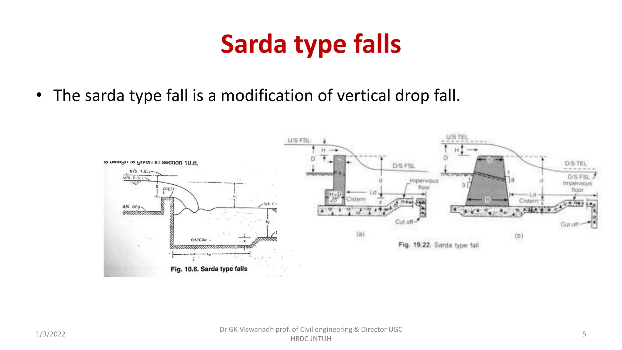
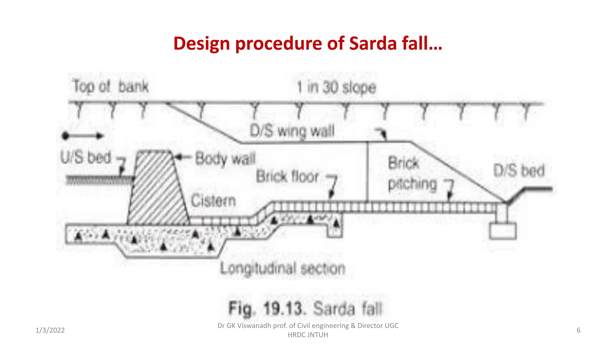
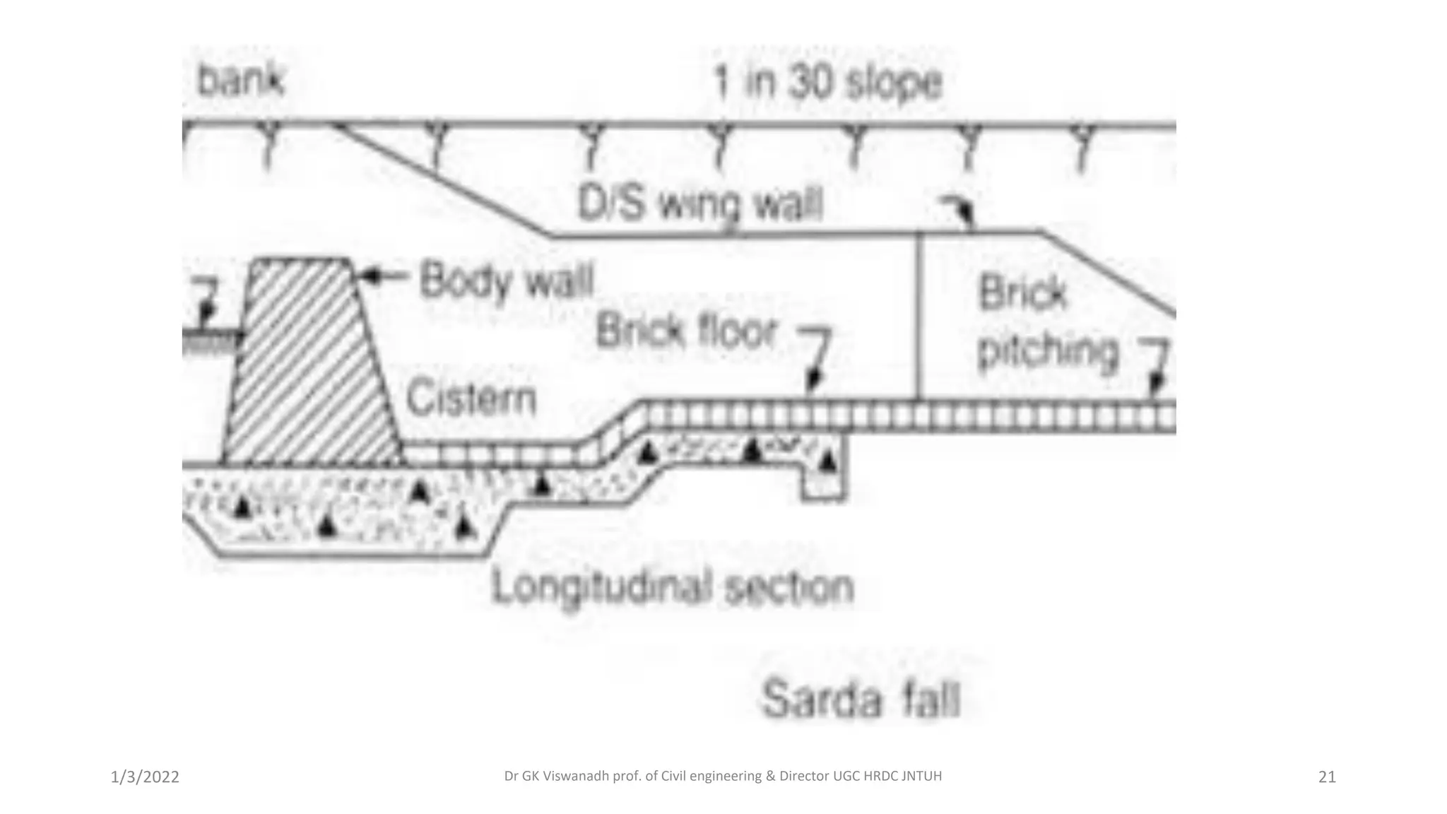
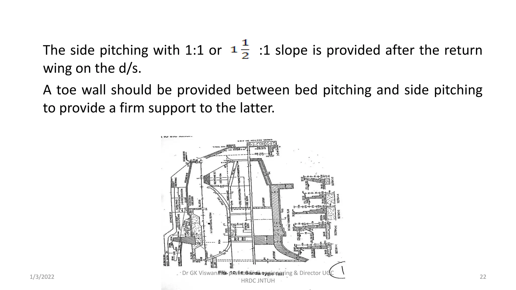
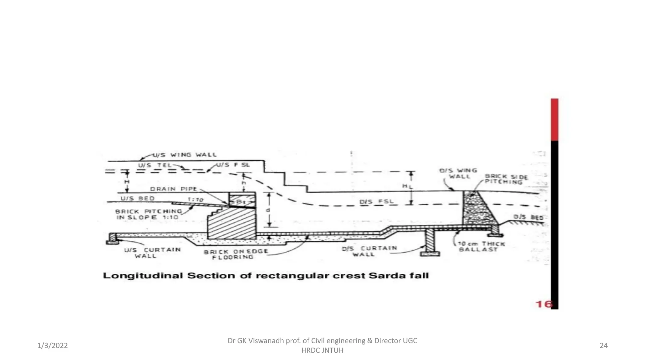
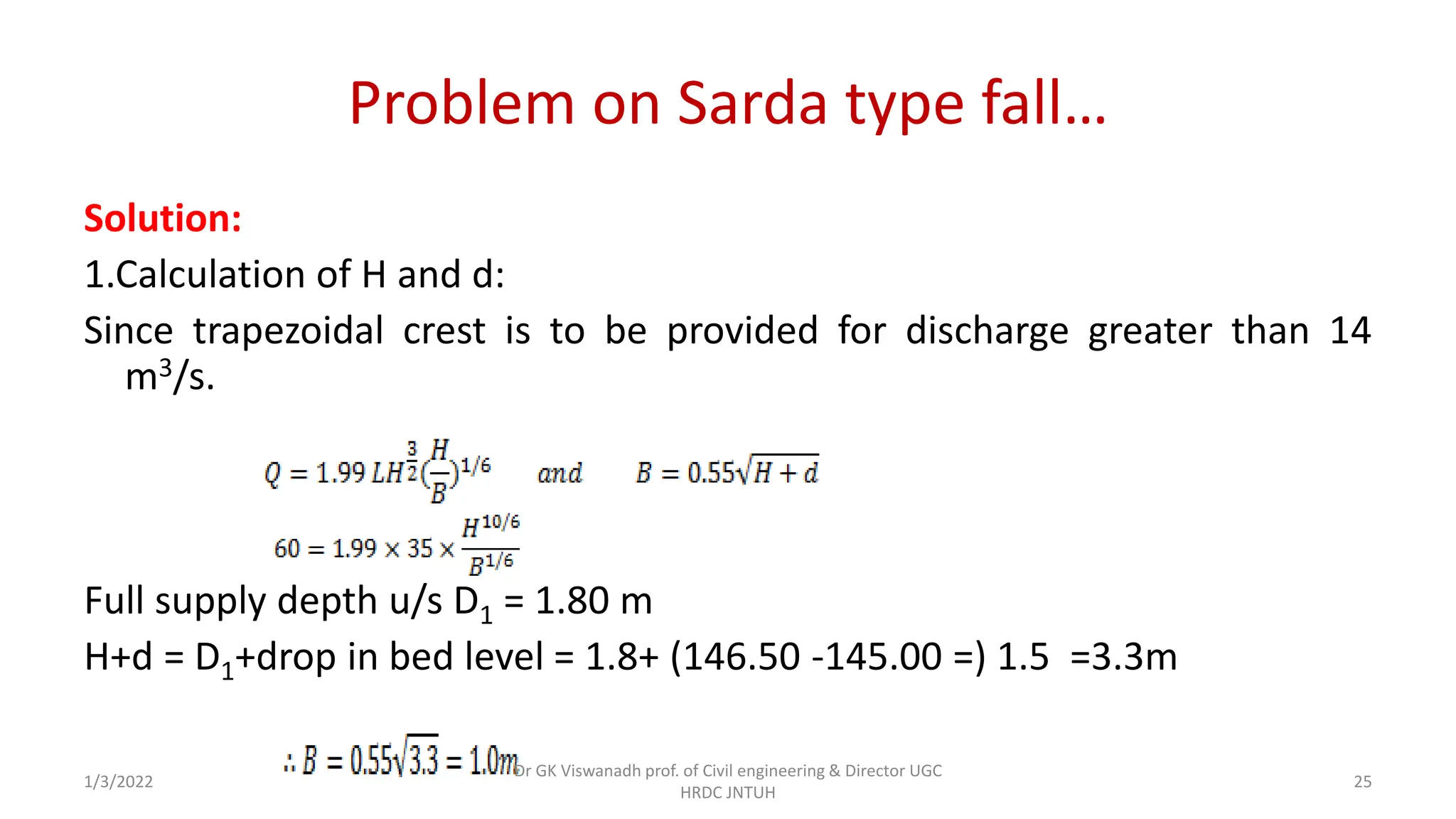
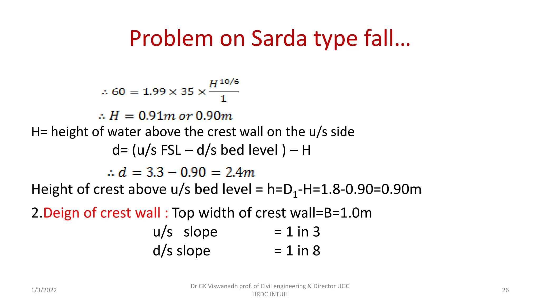
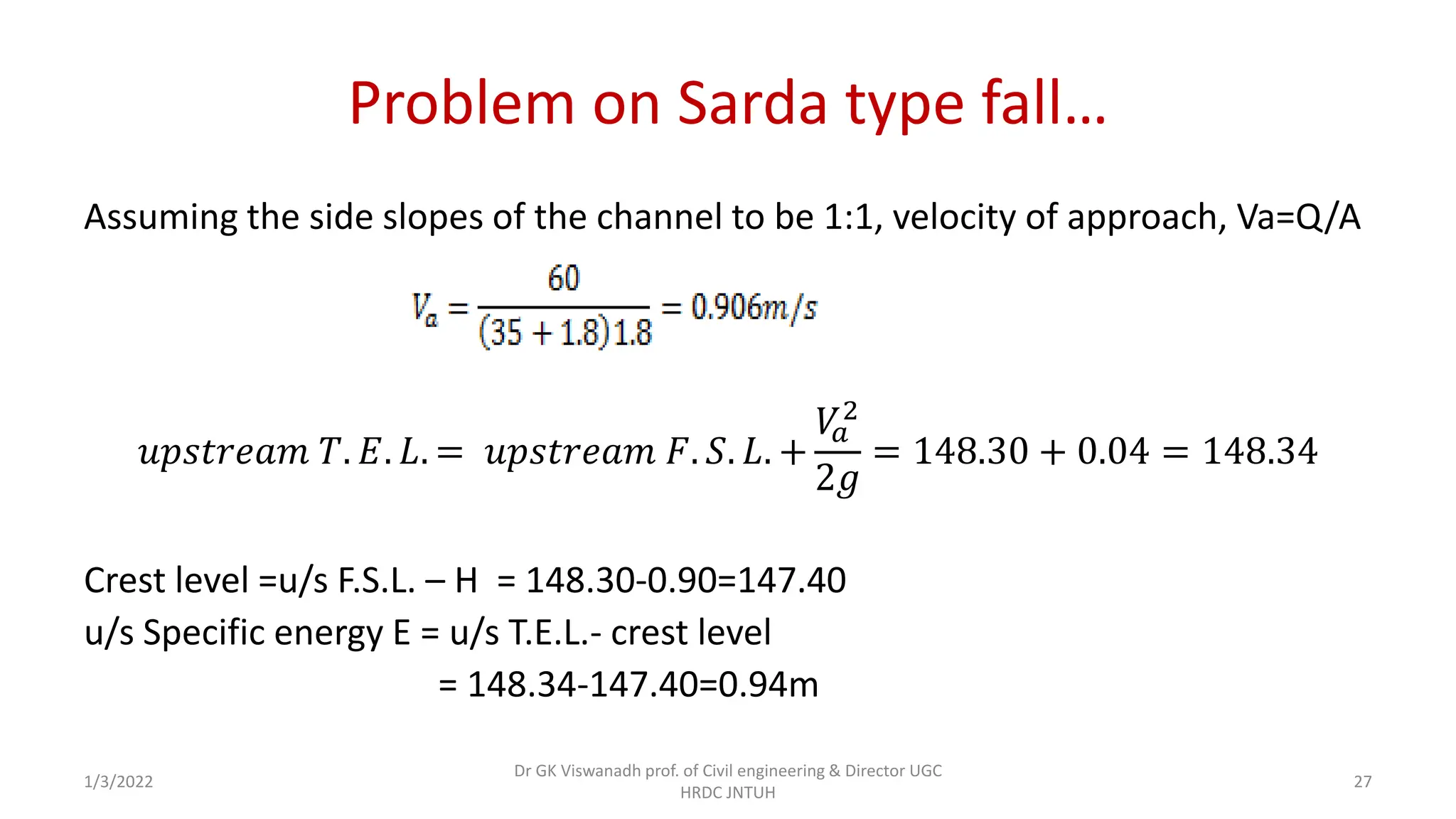
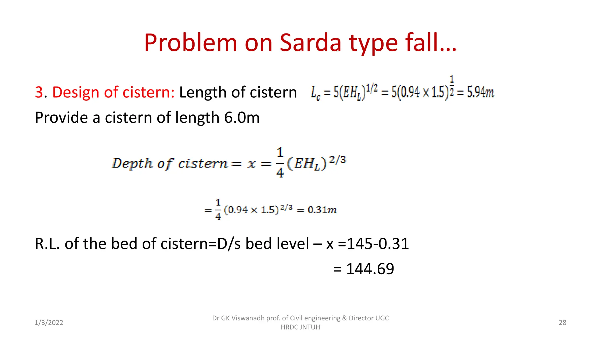
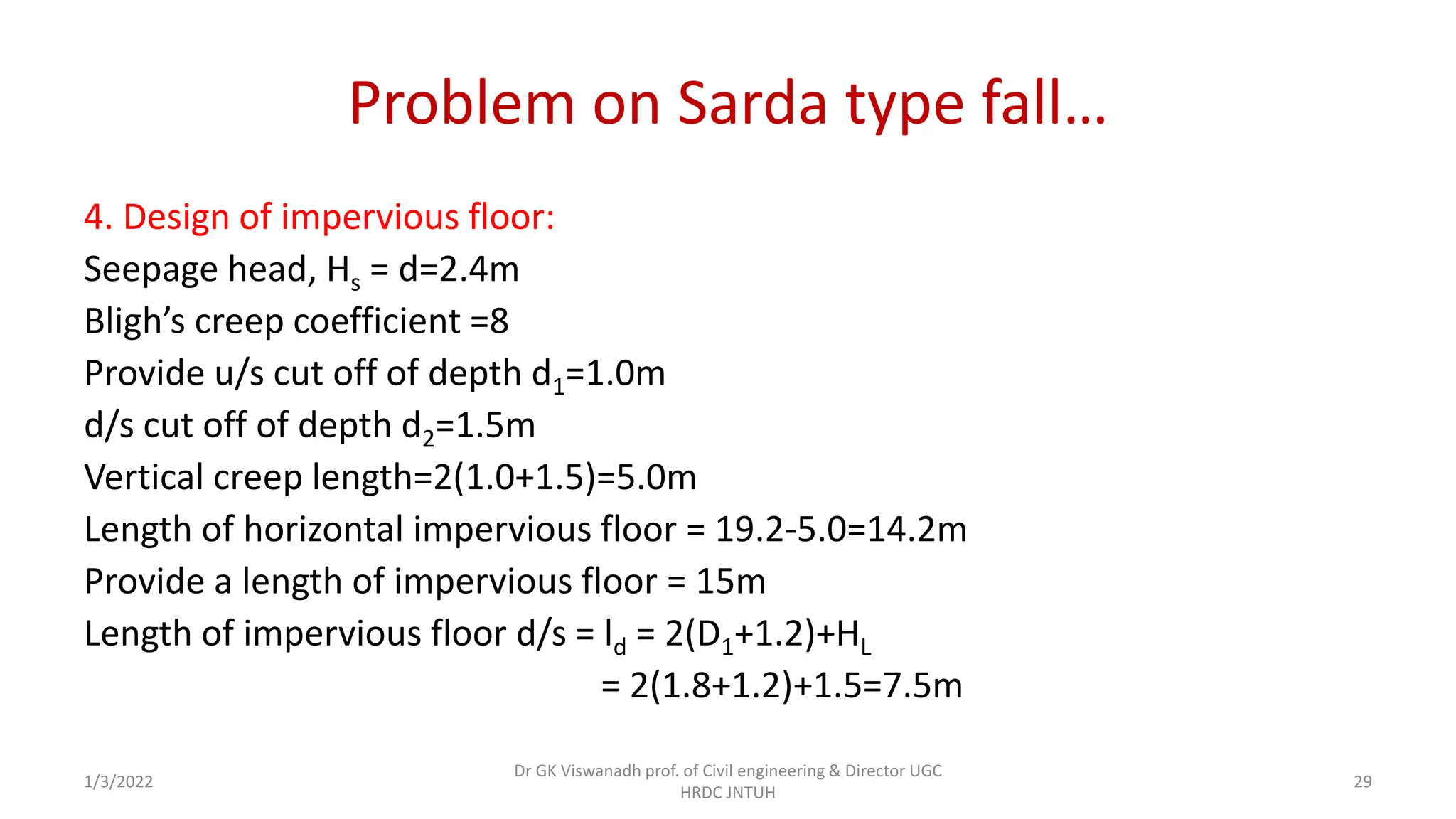
UNIT-V Canal Falls & Canal regulation works
• Canal Falls - Types of falls and their
location, Design principles of Notch
Fall and Sarada type Fall.
• Canal regulation works, principles of
design of distributary and head
regulators, Canal Cross Regulators -
canal outlets, types of canal modules,
proportionality, sensitivity and
flexibility. Cross Drainage works: types,
selection of site,
Dr GK Viswanadh Prof. of Civil Engineering & Director UGC-HRDC JNTUH 1/3/2022 1
Design procedure of Sarda fall
• Simple vertical drop fall or sarda fall consists, a vertical drop which
allows the upstream water to fall with sudden impact on downstream.
• The downstream acts like cushion for the upstream water and dissipate
extra energy.
• This type of fall was first introduced on the Sarda canal system in U.P.
based on the experiments carried out at Bahadarabad Research station,
U.P. Therefore, it is also called Sarda Fall.
• This is a vertical drop weir with rectangular crest for discharges less than
14m3/s.
1/3/2022
Dr GK Viswanadh prof. of Civil engineering & Director UGC
HRDC JNTUH
2
1/3/2022
Dr GK Viswanadh prof. of Civil engineering & Director UGC
HRDC JNTUH
3
• The various elements of the Sarda type fall are
(i) crest wall (body wall)
(ii) Cistern
(iii) Impervious floor
(iv) downstream protection and
(v) Upstream approach.
1/3/2022
Dr GK Viswanadh prof. of Civil engineering & Director UGC
HRDC JNTUH
4
Sarda type falls
• The sarda type fall is a modification of vertical drop fall.
1/3/2022
Dr GK Viswanadh prof. of Civil engineering & Director UGC
HRDC JNTUH
5
Design procedure of Sarda fall…
1/3/2022
Dr GK Viswanadh prof. of Civil engineering & Director UGC
HRDC JNTUH
6
Design criteria
The design criteria of the various elements are as follows:
Crest Wall:
• The crest wall may be designed either for free flow conditions or for submerged
flow condition.
• The discharge equations adopted for rectangular and trapezoidal crests are as
follows.
Rectangular crest weir with free flow:𝑸 = 𝟏. 𝟖𝟑𝟓 𝑳𝑯
𝟑
𝟐
𝑯
𝑩
𝟏
𝟔
here Q = discharge in m3/s
L= Length of crest wall(m)
H= height of water above the crest wall on the u/s side (m)
B= top width of crest(m)
1/3/2022
Dr GK Viswanadh prof. of Civil engineering & Director UGC
HRDC JNTUH
7
Trapezoidal weir with free flow: 𝑄 = 1.99 𝐿𝐻
3
2
𝐻
𝐵
1
6
For drowned condition of both types of weirs, neglecting velocity of
approach with a coefficient of discharge Cd for free and drowned
portions,
Where HL = drop in the water surface , m
and hd = height of the water surface on the d/s side above the crest of the
weir, in m.
1/3/2022
Dr GK Viswanadh prof. of Civil engineering & Director UGC
HRDC JNTUH
8
Width of the crest wall; B:
for rectangular crest wall
Where B= top width of crest wall in m B1 = base width of the crest wall (m)
H= height of water surface above the top of crest wall u/s
s= specific gravity of the material of crest wall
And for trapezoidal crest wall,
with side slope of u/s face as 1 in 3 and
side slope of d/s face as 1 in 8.
The stability of the crest wall shall be checked for fall over 1.5m.
1/3/2022
Dr GK Viswanadh prof. of Civil engineering & Director UGC
HRDC JNTUH
9
Crest level:
Crest level = u/s F.S.L.- H for free overfall condition
If the height of crest wall above u/s bed is h, and
u/s full supply depth = D1,
h= D1-H
for drowned condition, h=D1-(HL + hd)
f
1/3/2022
Dr GK Viswanadh prof. of Civil engineering & Director UGC
HRDC JNTUH
10
Cistern : Length of cistern =
Where E is the depth of crest below the u/s T.E.L.
Impervious floor: Total length of impervious floor shall be designed based
on Bligh’s or Khosla’s theory.
Minimum length of d/s impervious floor
1/3/2022
Dr GK Viswanadh prof. of Civil engineering & Director UGC
HRDC JNTUH
11
1/3/2022
Dr GK Viswanadh prof. of Civil engineering & Director UGC
HRDC JNTUH
12
1/3/2022
Dr GK Viswanadh prof. of Civil engineering & Director UGC
HRDC JNTUH
13
• The d/s floor should be made thick enough to resist the uplift pressures,
the minimum thickness should be limited to 45cm on concrete under
35cm of brick masonry.
• A sufficient depth of cutoff below the floor should be provided at the
d/s end of floor for safety against exit gradient.
Minimum depth of u/s cutoff = where D1 = u/s F.S.D.
Minimum depth of d/s cutoff = , where D2= d/s F.S.D.
1/3/2022
Dr GK Viswanadh prof. of Civil engineering & Director UGC
HRDC JNTUH
14
Energy Dissipators:
• For large discharges, two rows of friction blocks in the cistern and two
rows of chute blocks on the impervious floor at the d/s end shall be
provided as additional energy dissipators.
• Both friction blocks and chute blocks are staggered and the size and
position of these blocks are follows:
1/3/2022
Dr GK Viswanadh prof. of Civil engineering & Director UGC
HRDC JNTUH
15
Friction blocks: Length = 2 dc
Width = dc
Height = dc
Distance of the first row from the d/s toe of crest wall = 1.5 dc.
Spacing between two rows = dc
spacing between the block in the same row = 2dc
where dc = critical depth =
1/3/2022
Dr GK Viswanadh prof. of Civil engineering & Director UGC
HRDC JNTUH
16
1/3/2022
Dr GK Viswanadh prof. of Civil engineering & Director UGC
HRDC JNTUH
17
Chute Blocks:
Length= width = Height =
Spacing between two rows=
Spacing between blocks in same row=
• Where D2 is the full supply depth downstream.
• One row of chute blocks is provided just at the d/s end of
impervious floor and the other upstream of the above row.
1/3/2022
Dr GK Viswanadh prof. of Civil engineering & Director UGC
HRDC JNTUH
18
Protection works:
• Bed protection u/s of crest wall: Brick pitching is laid on the
channel bed for 2 to 4m, length adjacent to the crest wall on
the u/s side with a downward slope of 1 in 10 towards the
crest wall.
• At the level of brick pitching a few drain holes are provided in
the crest wall for draining purpose during canal closure.
1/3/2022
Dr GK Viswanadh prof. of Civil engineering & Director UGC
HRDC JNTUH
19
Upstream Wings: are kept segmental with a radius of 6HL, subtending an
angle of 60° at the centre and continued thereafter tangentially into the
bank by a minimum of 1m.
Bed Protection d/s : The d/s bed pitching is kept horizontal for a length of
6m and sloped at 1 in 10 thereafter for a length of 5 to 15m for falls
varying from 0.75m to 1.5m.
The d/s wing walls are kept vertical for a length of 5 to 8 times from
the crest and then flared or wraped from vertical to 1:1 or : 1 at end of
flooring
1/3/2022
Dr GK Viswanadh prof. of Civil engineering & Director UGC
HRDC JNTUH
20
1/3/2022 Dr GK Viswanadh prof. of Civil engineering & Director UGC HRDC JNTUH 21
The side pitching with 1:1 or :1 slope is provided after the return
wing on the d/s.
A toe wall should be provided between bed pitching and side pitching
to provide a firm support to the latter.
1/3/2022
Dr GK Viswanadh prof. of Civil engineering & Director UGC
HRDC JNTUH
22
Problem on Sarda type fall
Design a Sarda type fall with the following data.
Full supply discharge=60m3/s.
Full supply level u/s=148.30m d/s=146.80m
F.S.D u/s=1.8m d/s=1.8m
Bed width u/s=35m d/s=35m
Bed level u/s=146.50 d/s=145.00
Drop = 1.5m
Design the floor on the basis of Bligh’s theory assuming the creep
coefficient to be 8.
1/3/2022
Dr GK Viswanadh prof. of Civil engineering & Director UGC
HRDC JNTUH
23
1/3/2022
Dr GK Viswanadh prof. of Civil engineering & Director UGC
HRDC JNTUH
24
Problem on Sarda type fall…
Solution:
1.Calculation of H and d:
Since trapezoidal crest is to be provided for discharge greater than 14
m3/s.
Full supply depth u/s D1 = 1.80 m
H+d = D1+drop in bed level = 1.8+ (146.50 -145.00 =) 1.5 =3.3m
1/3/2022
Dr GK Viswanadh prof. of Civil engineering & Director UGC
HRDC JNTUH
25
Problem on Sarda type fall…
H= height of water above the crest wall on the u/s side
d= (u/s FSL – d/s bed level ) – H
Height of crest above u/s bed level = h=D1-H=1.8-0.90=0.90m
2.Deign of crest wall : Top width of crest wall=B=1.0m
u/s slope = 1 in 3
d/s slope = 1 in 8
1/3/2022
Dr GK Viswanadh prof. of Civil engineering & Director UGC
HRDC JNTUH
26
Problem on Sarda type fall…
Assuming the side slopes of the channel to be 1:1, velocity of approach, Va=Q/A
𝑢𝑝𝑠𝑡𝑟𝑒𝑎𝑚 𝑇. 𝐸. 𝐿. = 𝑢𝑝𝑠𝑡𝑟𝑒𝑎𝑚 𝐹. 𝑆. 𝐿. +
𝑉
𝑎
2
2𝑔
= 148.30 + 0.04 = 148.34
Crest level =u/s F.S.L. – H = 148.30-0.90=147.40
u/s Specific energy E = u/s T.E.L.- crest level
= 148.34-147.40=0.94m
1/3/2022
Dr GK Viswanadh prof. of Civil engineering & Director UGC
HRDC JNTUH
27
Problem on Sarda type fall…
3. Design of cistern: Length of cistern
Provide a cistern of length 6.0m
R.L. of the bed of cistern=D/s bed level – x =145-0.31
= 144.69
1/3/2022
Dr GK Viswanadh prof. of Civil engineering & Director UGC
HRDC JNTUH
28
Problem on Sarda type fall…
4. Design of impervious floor:
Seepage head, Hs = d=2.4m
Bligh’s creep coefficient =8
Provide u/s cut off of depth d1=1.0m
d/s cut off of depth d2=1.5m
Vertical creep length=2(1.0+1.5)=5.0m
Length of horizontal impervious floor = 19.2-5.0=14.2m
Provide a length of impervious floor = 15m
Length of impervious floor d/s = ld = 2(D1+1.2)+HL
= 2(1.8+1.2)+1.5=7.5m
1/3/2022
Dr GK Viswanadh prof. of Civil engineering & Director UGC
HRDC JNTUH
29
Problem on Sarda type fall…
Provide ld=8.0m Length of impervious floor under the crest wall and
u/s = 15-8 = 7.0m
Total creep length = 15+2(1.0+1.5)=20m
Provide a nominal thick for the floor u/s of crest wall
= 2.4X0.55+0.31=1.63m
Thickness of floor say 1.4m
Provide 1.4 thick c.c floor over laid by 0.2m brick pitching:
Provide 1.4m thickness of 0.6m over laid by 0.2m thick brick pitching at
the d/s end of floor.
1/3/2022
Dr GK Viswanadh prof. of Civil engineering & Director UGC
HRDC JNTUH
30
Problem on Sarda type fall…
5. Design of d/s wings
Provide d/s wings vertical for a length of
The wings are then to be wrapped to 1:1 slope at a splay of 1 in 3.
Height of the top of d/s wing wall above bed = F.S.d+free board.
= 1.8+0.5=2.3m
Horizontal projection of the wrapped wing on 1:1 slope=2.3m
With a splay of 1 in 3, length of warped wing, measured along the centre
line of canal=2.3X3=6.9 0r 7.0m
Flooring and curtain walls to be checked for uplift and exit gradient by
Khosla’s theory.
1/3/2022
Dr GK Viswanadh prof. of Civil engineering & Director UGC
HRDC JNTUH
31
Problem on Sarda type fall…
6. D/S Protection:
(i) Bed pitching: Provide 200mm thick dry pitching
Length of bed pitching=9+2HL = 9+2X1.5=12m
This should be horizontal upto the end of wing walls and then slope at 1 in
10.
Warped wings commence 1m u/s of the d/s end of impervious floor.
Length of the sloping pitching = 12-6 = 6m
(ii) Curtain wall at the end of bed pitching : Thickness of curtain wall=0.4m
Depth of curtain wall =1m say.
1/3/2022
Dr GK Viswanadh prof. of Civil engineering & Director UGC
HRDC JNTUH
32
Problem on Sarda type fall…
(iii) Side pitching: Provide 20cm thick side pitching, warping from a slope
of 1:1 to and curtailed at an angle of 45°from the end of bed
pitching in plan.
(iv) Toe wall : Thickness = 0.4m
(v) Energy dissipator: Friction blocks and cube blocks are provided as
follows.
Critical depth,
1/3/2022
Dr GK Viswanadh prof. of Civil engineering & Director UGC
HRDC JNTUH
33
Problem on Sarda type fall…
Friction blocks: Length = 2 dc Width = dc Height = dc
Length = 2x0.7=1.4m
Width = 0.7m
Height = 0.7m
Distance of the first row from d/s toe of crest wall =1.5x0.7=1.05 or 1.0m
Spacing of blocks between two rows = 0.7m
Spacing of blocks in the same row=2x0.7=1.4m
Provide two rows of staggered friction blocks of size 1.4x0.7=0.7m in the
cistern.
1/3/2022
Dr GK Viswanadh prof. of Civil engineering & Director UGC
HRDC JNTUH
34
Problem on Sarda type fall…
Chute blocks : d/s water depth = 1.8m
Length = width = height=
Spacing between two rows=0.2m
Spacing between blocks in a row = 0.2m
• Provide two rows of staggered cube blocks of size 0.2x0.2x0.2m on
impervious floor at d/s end with a spacing of 0.2m
1/3/2022
Dr GK Viswanadh prof. of Civil engineering & Director UGC
HRDC JNTUH
35
Problem on Sarda type fall…
7. Design of u/s approach:
Radius of curved portion of u/s wings=5 to 6 times H
= 5 to 6(0.91) = 4.55 or 5.46 or 5.5m
• Provide u/s wings having segmental portion of radius 5.5m and
subtending 60° at the centre from the u/s edge of crest wall.
• There after they are taken straight and embedded in the bank by 1.0m
room the F.S.L. line.
1/3/2022
Dr GK Viswanadh prof. of Civil engineering & Director UGC
HRDC JNTUH
36

cxlass 29 Design of Sarada type Fall.pdf

  • 1.
    UNIT-V Canal Falls& Canal regulation works • Canal Falls - Types of falls and their location, Design principles of Notch Fall and Sarada type Fall. • Canal regulation works, principles of design of distributary and head regulators, Canal Cross Regulators - canal outlets, types of canal modules, proportionality, sensitivity and flexibility. Cross Drainage works: types, selection of site, Dr GK Viswanadh Prof. of Civil Engineering & Director UGC-HRDC JNTUH 1/3/2022 1
  • 2.
    Design procedure ofSarda fall • Simple vertical drop fall or sarda fall consists, a vertical drop which allows the upstream water to fall with sudden impact on downstream. • The downstream acts like cushion for the upstream water and dissipate extra energy. • This type of fall was first introduced on the Sarda canal system in U.P. based on the experiments carried out at Bahadarabad Research station, U.P. Therefore, it is also called Sarda Fall. • This is a vertical drop weir with rectangular crest for discharges less than 14m3/s. 1/3/2022 Dr GK Viswanadh prof. of Civil engineering & Director UGC HRDC JNTUH 2
  • 3.
    1/3/2022 Dr GK Viswanadhprof. of Civil engineering & Director UGC HRDC JNTUH 3
  • 4.
    • The variouselements of the Sarda type fall are (i) crest wall (body wall) (ii) Cistern (iii) Impervious floor (iv) downstream protection and (v) Upstream approach. 1/3/2022 Dr GK Viswanadh prof. of Civil engineering & Director UGC HRDC JNTUH 4
  • 5.
    Sarda type falls •The sarda type fall is a modification of vertical drop fall. 1/3/2022 Dr GK Viswanadh prof. of Civil engineering & Director UGC HRDC JNTUH 5
  • 6.
    Design procedure ofSarda fall… 1/3/2022 Dr GK Viswanadh prof. of Civil engineering & Director UGC HRDC JNTUH 6
  • 7.
    Design criteria The designcriteria of the various elements are as follows: Crest Wall: • The crest wall may be designed either for free flow conditions or for submerged flow condition. • The discharge equations adopted for rectangular and trapezoidal crests are as follows. Rectangular crest weir with free flow:𝑸 = 𝟏. 𝟖𝟑𝟓 𝑳𝑯 𝟑 𝟐 𝑯 𝑩 𝟏 𝟔 here Q = discharge in m3/s L= Length of crest wall(m) H= height of water above the crest wall on the u/s side (m) B= top width of crest(m) 1/3/2022 Dr GK Viswanadh prof. of Civil engineering & Director UGC HRDC JNTUH 7
  • 8.
    Trapezoidal weir withfree flow: 𝑄 = 1.99 𝐿𝐻 3 2 𝐻 𝐵 1 6 For drowned condition of both types of weirs, neglecting velocity of approach with a coefficient of discharge Cd for free and drowned portions, Where HL = drop in the water surface , m and hd = height of the water surface on the d/s side above the crest of the weir, in m. 1/3/2022 Dr GK Viswanadh prof. of Civil engineering & Director UGC HRDC JNTUH 8
  • 9.
    Width of thecrest wall; B: for rectangular crest wall Where B= top width of crest wall in m B1 = base width of the crest wall (m) H= height of water surface above the top of crest wall u/s s= specific gravity of the material of crest wall And for trapezoidal crest wall, with side slope of u/s face as 1 in 3 and side slope of d/s face as 1 in 8. The stability of the crest wall shall be checked for fall over 1.5m. 1/3/2022 Dr GK Viswanadh prof. of Civil engineering & Director UGC HRDC JNTUH 9
  • 10.
    Crest level: Crest level= u/s F.S.L.- H for free overfall condition If the height of crest wall above u/s bed is h, and u/s full supply depth = D1, h= D1-H for drowned condition, h=D1-(HL + hd) f 1/3/2022 Dr GK Viswanadh prof. of Civil engineering & Director UGC HRDC JNTUH 10
  • 11.
    Cistern : Lengthof cistern = Where E is the depth of crest below the u/s T.E.L. Impervious floor: Total length of impervious floor shall be designed based on Bligh’s or Khosla’s theory. Minimum length of d/s impervious floor 1/3/2022 Dr GK Viswanadh prof. of Civil engineering & Director UGC HRDC JNTUH 11
  • 12.
    1/3/2022 Dr GK Viswanadhprof. of Civil engineering & Director UGC HRDC JNTUH 12
  • 13.
    1/3/2022 Dr GK Viswanadhprof. of Civil engineering & Director UGC HRDC JNTUH 13
  • 14.
    • The d/sfloor should be made thick enough to resist the uplift pressures, the minimum thickness should be limited to 45cm on concrete under 35cm of brick masonry. • A sufficient depth of cutoff below the floor should be provided at the d/s end of floor for safety against exit gradient. Minimum depth of u/s cutoff = where D1 = u/s F.S.D. Minimum depth of d/s cutoff = , where D2= d/s F.S.D. 1/3/2022 Dr GK Viswanadh prof. of Civil engineering & Director UGC HRDC JNTUH 14
  • 15.
    Energy Dissipators: • Forlarge discharges, two rows of friction blocks in the cistern and two rows of chute blocks on the impervious floor at the d/s end shall be provided as additional energy dissipators. • Both friction blocks and chute blocks are staggered and the size and position of these blocks are follows: 1/3/2022 Dr GK Viswanadh prof. of Civil engineering & Director UGC HRDC JNTUH 15
  • 16.
    Friction blocks: Length= 2 dc Width = dc Height = dc Distance of the first row from the d/s toe of crest wall = 1.5 dc. Spacing between two rows = dc spacing between the block in the same row = 2dc where dc = critical depth = 1/3/2022 Dr GK Viswanadh prof. of Civil engineering & Director UGC HRDC JNTUH 16
  • 17.
    1/3/2022 Dr GK Viswanadhprof. of Civil engineering & Director UGC HRDC JNTUH 17
  • 18.
    Chute Blocks: Length= width= Height = Spacing between two rows= Spacing between blocks in same row= • Where D2 is the full supply depth downstream. • One row of chute blocks is provided just at the d/s end of impervious floor and the other upstream of the above row. 1/3/2022 Dr GK Viswanadh prof. of Civil engineering & Director UGC HRDC JNTUH 18
  • 19.
    Protection works: • Bedprotection u/s of crest wall: Brick pitching is laid on the channel bed for 2 to 4m, length adjacent to the crest wall on the u/s side with a downward slope of 1 in 10 towards the crest wall. • At the level of brick pitching a few drain holes are provided in the crest wall for draining purpose during canal closure. 1/3/2022 Dr GK Viswanadh prof. of Civil engineering & Director UGC HRDC JNTUH 19
  • 20.
    Upstream Wings: arekept segmental with a radius of 6HL, subtending an angle of 60° at the centre and continued thereafter tangentially into the bank by a minimum of 1m. Bed Protection d/s : The d/s bed pitching is kept horizontal for a length of 6m and sloped at 1 in 10 thereafter for a length of 5 to 15m for falls varying from 0.75m to 1.5m. The d/s wing walls are kept vertical for a length of 5 to 8 times from the crest and then flared or wraped from vertical to 1:1 or : 1 at end of flooring 1/3/2022 Dr GK Viswanadh prof. of Civil engineering & Director UGC HRDC JNTUH 20
  • 21.
    1/3/2022 Dr GKViswanadh prof. of Civil engineering & Director UGC HRDC JNTUH 21
  • 22.
    The side pitchingwith 1:1 or :1 slope is provided after the return wing on the d/s. A toe wall should be provided between bed pitching and side pitching to provide a firm support to the latter. 1/3/2022 Dr GK Viswanadh prof. of Civil engineering & Director UGC HRDC JNTUH 22
  • 23.
    Problem on Sardatype fall Design a Sarda type fall with the following data. Full supply discharge=60m3/s. Full supply level u/s=148.30m d/s=146.80m F.S.D u/s=1.8m d/s=1.8m Bed width u/s=35m d/s=35m Bed level u/s=146.50 d/s=145.00 Drop = 1.5m Design the floor on the basis of Bligh’s theory assuming the creep coefficient to be 8. 1/3/2022 Dr GK Viswanadh prof. of Civil engineering & Director UGC HRDC JNTUH 23
  • 24.
    1/3/2022 Dr GK Viswanadhprof. of Civil engineering & Director UGC HRDC JNTUH 24
  • 25.
    Problem on Sardatype fall… Solution: 1.Calculation of H and d: Since trapezoidal crest is to be provided for discharge greater than 14 m3/s. Full supply depth u/s D1 = 1.80 m H+d = D1+drop in bed level = 1.8+ (146.50 -145.00 =) 1.5 =3.3m 1/3/2022 Dr GK Viswanadh prof. of Civil engineering & Director UGC HRDC JNTUH 25
  • 26.
    Problem on Sardatype fall… H= height of water above the crest wall on the u/s side d= (u/s FSL – d/s bed level ) – H Height of crest above u/s bed level = h=D1-H=1.8-0.90=0.90m 2.Deign of crest wall : Top width of crest wall=B=1.0m u/s slope = 1 in 3 d/s slope = 1 in 8 1/3/2022 Dr GK Viswanadh prof. of Civil engineering & Director UGC HRDC JNTUH 26
  • 27.
    Problem on Sardatype fall… Assuming the side slopes of the channel to be 1:1, velocity of approach, Va=Q/A 𝑢𝑝𝑠𝑡𝑟𝑒𝑎𝑚 𝑇. 𝐸. 𝐿. = 𝑢𝑝𝑠𝑡𝑟𝑒𝑎𝑚 𝐹. 𝑆. 𝐿. + 𝑉 𝑎 2 2𝑔 = 148.30 + 0.04 = 148.34 Crest level =u/s F.S.L. – H = 148.30-0.90=147.40 u/s Specific energy E = u/s T.E.L.- crest level = 148.34-147.40=0.94m 1/3/2022 Dr GK Viswanadh prof. of Civil engineering & Director UGC HRDC JNTUH 27
  • 28.
    Problem on Sardatype fall… 3. Design of cistern: Length of cistern Provide a cistern of length 6.0m R.L. of the bed of cistern=D/s bed level – x =145-0.31 = 144.69 1/3/2022 Dr GK Viswanadh prof. of Civil engineering & Director UGC HRDC JNTUH 28
  • 29.
    Problem on Sardatype fall… 4. Design of impervious floor: Seepage head, Hs = d=2.4m Bligh’s creep coefficient =8 Provide u/s cut off of depth d1=1.0m d/s cut off of depth d2=1.5m Vertical creep length=2(1.0+1.5)=5.0m Length of horizontal impervious floor = 19.2-5.0=14.2m Provide a length of impervious floor = 15m Length of impervious floor d/s = ld = 2(D1+1.2)+HL = 2(1.8+1.2)+1.5=7.5m 1/3/2022 Dr GK Viswanadh prof. of Civil engineering & Director UGC HRDC JNTUH 29
  • 30.
    Problem on Sardatype fall… Provide ld=8.0m Length of impervious floor under the crest wall and u/s = 15-8 = 7.0m Total creep length = 15+2(1.0+1.5)=20m Provide a nominal thick for the floor u/s of crest wall = 2.4X0.55+0.31=1.63m Thickness of floor say 1.4m Provide 1.4 thick c.c floor over laid by 0.2m brick pitching: Provide 1.4m thickness of 0.6m over laid by 0.2m thick brick pitching at the d/s end of floor. 1/3/2022 Dr GK Viswanadh prof. of Civil engineering & Director UGC HRDC JNTUH 30
  • 31.
    Problem on Sardatype fall… 5. Design of d/s wings Provide d/s wings vertical for a length of The wings are then to be wrapped to 1:1 slope at a splay of 1 in 3. Height of the top of d/s wing wall above bed = F.S.d+free board. = 1.8+0.5=2.3m Horizontal projection of the wrapped wing on 1:1 slope=2.3m With a splay of 1 in 3, length of warped wing, measured along the centre line of canal=2.3X3=6.9 0r 7.0m Flooring and curtain walls to be checked for uplift and exit gradient by Khosla’s theory. 1/3/2022 Dr GK Viswanadh prof. of Civil engineering & Director UGC HRDC JNTUH 31
  • 32.
    Problem on Sardatype fall… 6. D/S Protection: (i) Bed pitching: Provide 200mm thick dry pitching Length of bed pitching=9+2HL = 9+2X1.5=12m This should be horizontal upto the end of wing walls and then slope at 1 in 10. Warped wings commence 1m u/s of the d/s end of impervious floor. Length of the sloping pitching = 12-6 = 6m (ii) Curtain wall at the end of bed pitching : Thickness of curtain wall=0.4m Depth of curtain wall =1m say. 1/3/2022 Dr GK Viswanadh prof. of Civil engineering & Director UGC HRDC JNTUH 32
  • 33.
    Problem on Sardatype fall… (iii) Side pitching: Provide 20cm thick side pitching, warping from a slope of 1:1 to and curtailed at an angle of 45°from the end of bed pitching in plan. (iv) Toe wall : Thickness = 0.4m (v) Energy dissipator: Friction blocks and cube blocks are provided as follows. Critical depth, 1/3/2022 Dr GK Viswanadh prof. of Civil engineering & Director UGC HRDC JNTUH 33
  • 34.
    Problem on Sardatype fall… Friction blocks: Length = 2 dc Width = dc Height = dc Length = 2x0.7=1.4m Width = 0.7m Height = 0.7m Distance of the first row from d/s toe of crest wall =1.5x0.7=1.05 or 1.0m Spacing of blocks between two rows = 0.7m Spacing of blocks in the same row=2x0.7=1.4m Provide two rows of staggered friction blocks of size 1.4x0.7=0.7m in the cistern. 1/3/2022 Dr GK Viswanadh prof. of Civil engineering & Director UGC HRDC JNTUH 34
  • 35.
    Problem on Sardatype fall… Chute blocks : d/s water depth = 1.8m Length = width = height= Spacing between two rows=0.2m Spacing between blocks in a row = 0.2m • Provide two rows of staggered cube blocks of size 0.2x0.2x0.2m on impervious floor at d/s end with a spacing of 0.2m 1/3/2022 Dr GK Viswanadh prof. of Civil engineering & Director UGC HRDC JNTUH 35
  • 36.
    Problem on Sardatype fall… 7. Design of u/s approach: Radius of curved portion of u/s wings=5 to 6 times H = 5 to 6(0.91) = 4.55 or 5.46 or 5.5m • Provide u/s wings having segmental portion of radius 5.5m and subtending 60° at the centre from the u/s edge of crest wall. • There after they are taken straight and embedded in the bank by 1.0m room the F.S.L. line. 1/3/2022 Dr GK Viswanadh prof. of Civil engineering & Director UGC HRDC JNTUH 36