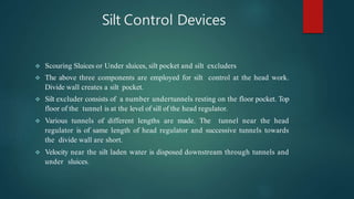
CANAL REGULATIONS
CANAL REGULATION
Introduction:
 Canal regulation is the process of regulating water from a reservoir or diversion
head works through a canal system for a dependable supply of water for irrigation
requirement.
 The canal system plays a key role in regulating the irrigation water.
 The major components of a permanent canal system are discussed below.
Components of a permanent canal system
 Main canal
 Branch canal
 Distributaries
 Water courses
Components……
Main Canal (M):
 This canal takes off from the river and derives water through a regulator. For a certain
length in the beginning the canal may be in full cutting.
 Obviously direct flow irrigation from such a channel is not possible as its water surface
is below the general ground surface.
 The main function of the canal is to take the required amount of irrigation water at the
head and to deliver it in the canal system below.
Branch Canals (B):
 After the main canal comes in the tract which is to be irrigated by the canal system,
water is distributed over the entire commanded area.
 For this purpose the main canal is branched to cover the whole area. The bifurcated
canals are called branch canals or simply branches.
Components…
 From the branches also direct irrigation is very rarely done.
 The main function of the branches is to make the water available in different parts of the
tract for further distribution. The section of a branch canal is smaller than the main canal.
Distributaries:
 They can be subdivided into:
 i. Major distributaries, and
 ii. Minor distributaries or minors.
Major Distributaries (D):
 They are also named Rajbaha. Major distributaries are smaller in section than the branches.
They are taken off mainly from the branches to distribute the water to various parts for
direct irrigation purposes.
Components…
 Sometimes major distributaries may take off directly from the main canal.
 The distributaries provide water to field channels through outlets for irrigation.
Minor Distributaries (M):
 They are smaller in section than the major distributaries. The main purpose of these
distributaries is to reduce the length of the field channels.
 They are taken off from the major distributaries and sometimes from the branch
canals.
 When the length of the field channels is more than 3 km the minor distributaries
are introduced to reduce the length.
 They are also called minors.
Components…
Water Courses:
 They are also named as guls or field channels. They are the channels which take
irrigation water to the fields.
 The water courses derive their supply from the distributaries through outlets.
 An outlet is a simple and a small irrigation structure constructed on the distributaries.
 It may be a simple pipe outlet or any other type provided to allow flow of water into
the water courses.
 Irrigation department is responsible for construction and maintenance of the canal
system up to minor distributaries.
 The field channels are constructed by cultivators themselves as per the alignment
sanctioned by the department.
Components…
 Nowadays the field channels are also constructed by irrigation department for
cultivators.
 The job of maintenance of field channels is left entirely to the cultivators. The length
of a water course should not exceed 3 km in any case.
 It generally serves an area of 40 to 50 hectares. The upper limit of discharge in a
watercourse ranges between 0.08 to 0.06 m3/sec.
Canal Regulation Works
 These are structures constructed to regulate the flow rate and volume of water
 Necessary for the efficient working and safety of an irrigation channel
Important Regulators
 Head regulator or head sluice
 Cross regulator
 Canal outlet
 Regulators are normally aligned at 90 degree to weir.
Head Regulator
 Regulators Constructed at the off taking point are called head
regulators.
 When it is constructed at the head of main canal it is known as canal
head regulator.
 And when it is constructed at the head of distributary, it is called
distributary head regulator.
 Function:
 To control the entry of water either from the reservoir or from
the main canal.
 Tocontrol the entry of silt into off taking or main canal.
 Toserve as a meter for measuring discharge of water.
Head Regulator
 Construction: The components of head regulator depends upon
the size of canal and location of head regulator.
 It consists of one or more gated research openings with barrels
running through the bank.
 For large canals head regulators are flumed to facilitate the
measurement of discharge.
Head Regulator
Cross Regulator
 Cross Regulator
 ARegulator Constructed in the main canal or parent canal downstream of an
off take canal is called cross- regulator.
 It is generally constructed at a distance of 9 to 12 km along the main canal and
6 to 10 km along branch canal.
 Functions:
 (i) ToControl the flow of water in canal system
 (ii) Tofeed the off taking Canals
 (iii) Toenable closing of the canal breaches
 (iv) Toprovide roadway for vehicular traffic
Cross Regulator
 The sill of regulation is kept little higher than the u/s bed level of
canal across which it is constructed.
 Construction: For Cross Regulators abutments with grooves and
piers are constructed parallel to the parent canal.
 Vertical lift gates are fitted in the grooves. The gates can be
operate from the road.
Canal regulators
Canal regulators
Canal regulators
Types of Regulator
 Still pond regulation
 Open flow regulation
 Silt control devices
Still pond regulation:
 Canal draws water from still pond
 Water in excess of canal requirements is not allowed to escape under the
sluice gates.
 Velocity of water in the pocket is very much reduced; silt is deposited in
the pocket
 When the silt has a level about 1/2 to 1m below the crest level of Head
Regulator, supply in the canal is shut off and sluice gates are opened to
scour the deposited silt.

Open flow regulation
 Sluice gates are opened and allow excess of the canal requirement
 Top water passes into the canal
 Bottom water maintain certain velocity in the pocket to keep the silt to
remain in suspension
 Canal is not closed for scouring the silt.
Silt Control Devices
 Scouring Sluices or Under sluices, silt pocket and silt excluders
 The above three components are employed for silt control at the head work.
Divide wall creates a silt pocket.
 Silt excluder consists of a number undertunnels resting on the floor pocket. Top
floor of the tunnel is at the level of sill of the head regulator.
 Various tunnels of different lengths are made. The tunnel near the head
regulator is of same length of head regulator and successive tunnels towards
the divide wall are short.
 Velocity near the silt laden water is disposed downstream through tunnels and
under sluices.
Silt Control Devices
 Silt Excluder: The silt excluder is located on the u/s of diversion weir and in
front of the head regulator.
 The object is to remove silt that has entered in the stilling basin through
scouring sluices.
 Silt Ejector: Silt Ejector is located in the canal take off from the diversion weir at
6 to 10 km in the canal reach. It ejects the silt that has entered in the canal
 Installing silt excluders
 Making entry of clear top water by Providing raised sill in the canal
 Lower sill level of scouring sluices
 Wide head regulator reduces velocity of water at intake
 Smooth entry to avoid unsteady flow
 Handling careful the regulation of weir
 Disturbance is kept at minimum in weirs
 Silt excluder:
 Silt is excluded from water entering the canal, constructed in the bed
infront of head regulator - excludes silt from water entering the canal
 Designed such that the top and bottom layers of flow are separated with
the least possible disturbance
 Top water to canal - bottom, silt laden through under sluices
 No of tunnels resting on the floor of the pocket of different lengths
 The tunnel near the head regulator being of same length as that of the
width of head regulator - tunnel of different length.
 Capacity of tunnel is about 20% of canal discharge
 Minimum velocity 2 to 3 m/s to avoid deposition in tunnel is kept the
same as sill level of head regulator
 From discharge and scouring velocity the total waterway required for
under water tunnels can be determined
 Silt extractor or silt ejector:
 Device by which the silt, after it has entered the canal is extracted or
thrown out.
 Constructed on the canal some distance away from head regulator
 Horizontal diaphragm above the canal bed
 anal bed slightly depressed below the diaphragm 0.5 to 2.8m
 Under diaphragm, tunnel which extent the highly silted bottom water
tunnel.
 There should be no disturbance of flow at the entry.
 Sediment - laden are diverted by curved vanes
 Forwards the escape chamber: steep slope to escape channel is provided.
 The streamlined vane passage accelerate the flow through them, thus
avoiding deposition (decreasing section area increases the flow velocity)
 The tunnel discharge by gate at the outlet end (escape channel)
 Location:
 If near head regulator, silt will be in suspension
 If too far away than result in silting of canal.
 Classification of Regulators:

 I – According to purpose:
 1- Regulation of Discharge “Q”
 2- Regulation of Water slopes (and velocity)
 3- Measurement of Discharge “Q”
 4- Division or Diversion of Discharge
 5- Change in bed slope
 II – According to location
 1- Head Regulator
 2- Intermediate Regulator
 3- Escape Regulator
 4- Diversion Regulator

 III – According to Material (Type of Construction)
 1- Masonry Arch Regulator
 2- Mixed Type Regulator (masonry + RC)
 3- RC Regulator
 Location of regulators
 Should always be located at straight reaches (position “a”)
 Never located within curves in waterways (either silting or scouring is
liable to occur causing destruction of the regulator (position “b”)
 At diversion; location should be chosen 50-200m DS the point of
“c”
Should always be located at straight reaches (position “a”)
 Advantages of Regulators to weirs
 Regulator may be fully opened at flood time giving enough water way
area to avoid excess heading up
 both US & DS water levels are controlled
 minimize silting at US
Principles of Design
 Hydraulic Design
 To get the area of water way
 Discharge is considered for fully opened
 Regulator
 Determination of heading up
 Check the velocity through regulator vents
 Floor design
 To determine the floor length
 To cover the floor length by regulator floor
 To check the percolation length
 To determine the floor thickness
 To make adequate precautions against
 undesired percolation
 Structural Design
 To determine the dimensions and check the stability of the structural
elements which are: Piers; Abutments; wing walls Roadway (bridge);
gates Cranes and lifting devices
 Main Elements of Regulators
 1- The water area of vents (S*dw)
 2- The bridge
 3- The piers between the regulator vents
 4- The abutments
 5- The floor
 6- The gates
 Forces acting on Regulator
 Pu - Upstream water pressure
 PD - Downstream water pressure acting on the DS emergency
groove
 PL - Water pressure in lateral direction when one vent is
for repair
 PW - Wind pressure on exposed surface (if any)
 W1 - Weight of bridge + live load (for worst case of loading)
 W2 - Own weight of pier
 W3 - Own weight of gates + lifting apparatus (if any
CANAL REGULATIONS
CANAL REGULATIONS

CANAL REGULATIONS

  • 1.
  • 2.
    CANAL REGULATION Introduction:  Canalregulation is the process of regulating water from a reservoir or diversion head works through a canal system for a dependable supply of water for irrigation requirement.  The canal system plays a key role in regulating the irrigation water.  The major components of a permanent canal system are discussed below. Components of a permanent canal system  Main canal  Branch canal  Distributaries  Water courses
  • 3.
    Components…… Main Canal (M): This canal takes off from the river and derives water through a regulator. For a certain length in the beginning the canal may be in full cutting.  Obviously direct flow irrigation from such a channel is not possible as its water surface is below the general ground surface.  The main function of the canal is to take the required amount of irrigation water at the head and to deliver it in the canal system below. Branch Canals (B):  After the main canal comes in the tract which is to be irrigated by the canal system, water is distributed over the entire commanded area.  For this purpose the main canal is branched to cover the whole area. The bifurcated canals are called branch canals or simply branches.
  • 4.
    Components…  From thebranches also direct irrigation is very rarely done.  The main function of the branches is to make the water available in different parts of the tract for further distribution. The section of a branch canal is smaller than the main canal. Distributaries:  They can be subdivided into:  i. Major distributaries, and  ii. Minor distributaries or minors. Major Distributaries (D):  They are also named Rajbaha. Major distributaries are smaller in section than the branches. They are taken off mainly from the branches to distribute the water to various parts for direct irrigation purposes.
  • 5.
    Components…  Sometimes majordistributaries may take off directly from the main canal.  The distributaries provide water to field channels through outlets for irrigation. Minor Distributaries (M):  They are smaller in section than the major distributaries. The main purpose of these distributaries is to reduce the length of the field channels.  They are taken off from the major distributaries and sometimes from the branch canals.  When the length of the field channels is more than 3 km the minor distributaries are introduced to reduce the length.  They are also called minors.
  • 6.
    Components… Water Courses:  Theyare also named as guls or field channels. They are the channels which take irrigation water to the fields.  The water courses derive their supply from the distributaries through outlets.  An outlet is a simple and a small irrigation structure constructed on the distributaries.  It may be a simple pipe outlet or any other type provided to allow flow of water into the water courses.  Irrigation department is responsible for construction and maintenance of the canal system up to minor distributaries.  The field channels are constructed by cultivators themselves as per the alignment sanctioned by the department.
  • 7.
    Components…  Nowadays thefield channels are also constructed by irrigation department for cultivators.  The job of maintenance of field channels is left entirely to the cultivators. The length of a water course should not exceed 3 km in any case.  It generally serves an area of 40 to 50 hectares. The upper limit of discharge in a watercourse ranges between 0.08 to 0.06 m3/sec.
  • 9.
    Canal Regulation Works These are structures constructed to regulate the flow rate and volume of water  Necessary for the efficient working and safety of an irrigation channel Important Regulators  Head regulator or head sluice  Cross regulator  Canal outlet  Regulators are normally aligned at 90 degree to weir.
  • 10.
    Head Regulator  RegulatorsConstructed at the off taking point are called head regulators.  When it is constructed at the head of main canal it is known as canal head regulator.  And when it is constructed at the head of distributary, it is called distributary head regulator.  Function:  To control the entry of water either from the reservoir or from the main canal.  Tocontrol the entry of silt into off taking or main canal.  Toserve as a meter for measuring discharge of water.
  • 11.
    Head Regulator  Construction:The components of head regulator depends upon the size of canal and location of head regulator.  It consists of one or more gated research openings with barrels running through the bank.  For large canals head regulators are flumed to facilitate the measurement of discharge.
  • 12.
  • 13.
    Cross Regulator  CrossRegulator  ARegulator Constructed in the main canal or parent canal downstream of an off take canal is called cross- regulator.  It is generally constructed at a distance of 9 to 12 km along the main canal and 6 to 10 km along branch canal.  Functions:  (i) ToControl the flow of water in canal system  (ii) Tofeed the off taking Canals  (iii) Toenable closing of the canal breaches  (iv) Toprovide roadway for vehicular traffic
  • 14.
    Cross Regulator  Thesill of regulation is kept little higher than the u/s bed level of canal across which it is constructed.  Construction: For Cross Regulators abutments with grooves and piers are constructed parallel to the parent canal.  Vertical lift gates are fitted in the grooves. The gates can be operate from the road.
  • 15.
  • 16.
  • 17.
  • 18.
    Types of Regulator Still pond regulation  Open flow regulation  Silt control devices
  • 19.
    Still pond regulation: Canal draws water from still pond  Water in excess of canal requirements is not allowed to escape under the sluice gates.  Velocity of water in the pocket is very much reduced; silt is deposited in the pocket  When the silt has a level about 1/2 to 1m below the crest level of Head Regulator, supply in the canal is shut off and sluice gates are opened to scour the deposited silt. 
  • 21.
    Open flow regulation Sluice gates are opened and allow excess of the canal requirement  Top water passes into the canal  Bottom water maintain certain velocity in the pocket to keep the silt to remain in suspension  Canal is not closed for scouring the silt.
  • 22.
    Silt Control Devices Scouring Sluices or Under sluices, silt pocket and silt excluders  The above three components are employed for silt control at the head work. Divide wall creates a silt pocket.  Silt excluder consists of a number undertunnels resting on the floor pocket. Top floor of the tunnel is at the level of sill of the head regulator.  Various tunnels of different lengths are made. The tunnel near the head regulator is of same length of head regulator and successive tunnels towards the divide wall are short.  Velocity near the silt laden water is disposed downstream through tunnels and under sluices.
  • 23.
    Silt Control Devices Silt Excluder: The silt excluder is located on the u/s of diversion weir and in front of the head regulator.  The object is to remove silt that has entered in the stilling basin through scouring sluices.  Silt Ejector: Silt Ejector is located in the canal take off from the diversion weir at 6 to 10 km in the canal reach. It ejects the silt that has entered in the canal
  • 27.
     Installing siltexcluders  Making entry of clear top water by Providing raised sill in the canal  Lower sill level of scouring sluices  Wide head regulator reduces velocity of water at intake  Smooth entry to avoid unsteady flow  Handling careful the regulation of weir  Disturbance is kept at minimum in weirs
  • 28.
     Silt excluder: Silt is excluded from water entering the canal, constructed in the bed infront of head regulator - excludes silt from water entering the canal  Designed such that the top and bottom layers of flow are separated with the least possible disturbance  Top water to canal - bottom, silt laden through under sluices  No of tunnels resting on the floor of the pocket of different lengths  The tunnel near the head regulator being of same length as that of the width of head regulator - tunnel of different length.  Capacity of tunnel is about 20% of canal discharge
  • 29.
     Minimum velocity2 to 3 m/s to avoid deposition in tunnel is kept the same as sill level of head regulator  From discharge and scouring velocity the total waterway required for under water tunnels can be determined  Silt extractor or silt ejector:  Device by which the silt, after it has entered the canal is extracted or thrown out.  Constructed on the canal some distance away from head regulator  Horizontal diaphragm above the canal bed  anal bed slightly depressed below the diaphragm 0.5 to 2.8m
  • 30.
     Under diaphragm,tunnel which extent the highly silted bottom water tunnel.  There should be no disturbance of flow at the entry.  Sediment - laden are diverted by curved vanes  Forwards the escape chamber: steep slope to escape channel is provided.  The streamlined vane passage accelerate the flow through them, thus avoiding deposition (decreasing section area increases the flow velocity)  The tunnel discharge by gate at the outlet end (escape channel)
  • 31.
     Location:  Ifnear head regulator, silt will be in suspension  If too far away than result in silting of canal.
  • 32.
     Classification ofRegulators:   I – According to purpose:  1- Regulation of Discharge “Q”  2- Regulation of Water slopes (and velocity)  3- Measurement of Discharge “Q”  4- Division or Diversion of Discharge  5- Change in bed slope
  • 33.
     II –According to location  1- Head Regulator  2- Intermediate Regulator  3- Escape Regulator  4- Diversion Regulator   III – According to Material (Type of Construction)  1- Masonry Arch Regulator  2- Mixed Type Regulator (masonry + RC)  3- RC Regulator
  • 34.
     Location ofregulators  Should always be located at straight reaches (position “a”)  Never located within curves in waterways (either silting or scouring is liable to occur causing destruction of the regulator (position “b”)  At diversion; location should be chosen 50-200m DS the point of “c” Should always be located at straight reaches (position “a”)
  • 36.
     Advantages ofRegulators to weirs  Regulator may be fully opened at flood time giving enough water way area to avoid excess heading up  both US & DS water levels are controlled  minimize silting at US
  • 38.
    Principles of Design Hydraulic Design  To get the area of water way  Discharge is considered for fully opened  Regulator  Determination of heading up  Check the velocity through regulator vents
  • 39.
     Floor design To determine the floor length  To cover the floor length by regulator floor  To check the percolation length  To determine the floor thickness  To make adequate precautions against  undesired percolation
  • 40.
     Structural Design To determine the dimensions and check the stability of the structural elements which are: Piers; Abutments; wing walls Roadway (bridge); gates Cranes and lifting devices
  • 41.
     Main Elementsof Regulators  1- The water area of vents (S*dw)  2- The bridge  3- The piers between the regulator vents  4- The abutments  5- The floor  6- The gates
  • 43.
     Forces actingon Regulator  Pu - Upstream water pressure  PD - Downstream water pressure acting on the DS emergency groove  PL - Water pressure in lateral direction when one vent is for repair  PW - Wind pressure on exposed surface (if any)  W1 - Weight of bridge + live load (for worst case of loading)  W2 - Own weight of pier  W3 - Own weight of gates + lifting apparatus (if any