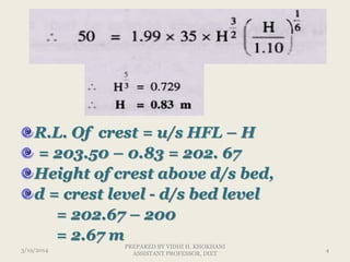
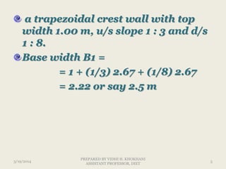
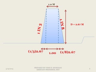
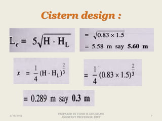
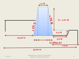
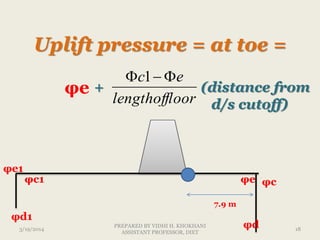
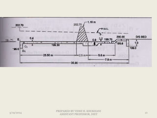
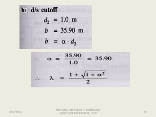
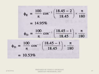
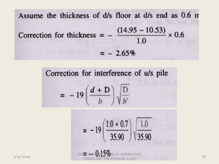
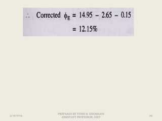
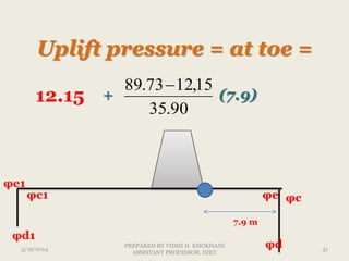
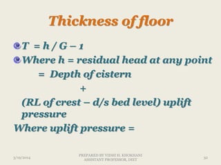
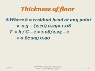
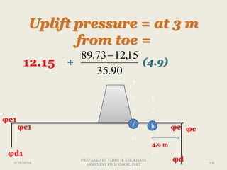
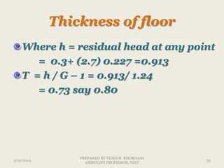
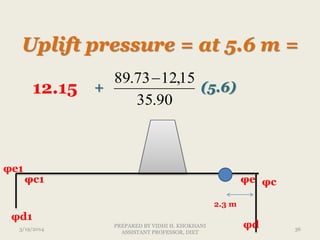
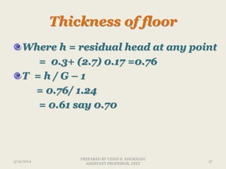
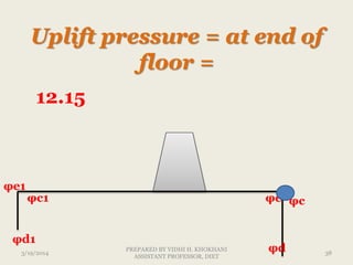
canal fall types,design steps of vertical drop fall, design of sheet pile, cistern, impervious floor, bligh creep theory, khosla theory, cutoff drop structure, wing walls
Section of an Earth Dam :
The design of an earth dam essentially consists of determining such a cross section
the dam which when constructed with the available materials will fulfill its required
tion with adequate safety. Thus there are two aspects of the design of an earth dam.
b) Foundation pervious to a moderate depth, after which impervious strata isavailable :
(c) Foundation pervious to a great depth:
CASE 2 ONLY FINE GRAVEL OR COARSE SAND IS AVAILABLE
PROVIDE DIAPHRAM TYPE DAM WITH SUITABLE ARRANGEMENTS
CASE 3
ONLY SILT AND CLAY IS AVAILABLE
NO CORE
ONLY IMPERVIOUS BLANKED AND ROCK TOE PROVIDES
SEEPAGE ANALYSIS
ASSUMPTIONS
FLOW IS – TWO DIMENTIONAL
Soil is INCOMPRESSIBLE SOIL
Soil is homogeneous and isotropic
Soil is fully saturated
Flow is steady
Darcys law is valid
Phreatic line – (seepage line)
Line within the dam section having positive hydrostatic pressure at below section and negative hydrostatic pressure at above section
Line has atmospheric pressure itself
Separation line of saturated and non saturated portion
Casagrande method of determining seepage line
Water flowing over a spillway acquires a lot of kinetic energy because of the conversio of the potential energy into kinetic energy.
If the water flowing with such a high velocity is discharged into the river it will scour the river bed.
If the scour is not properly controlled it may extend backward and may endanger the spillway and the dam.
FORCES ACTING ON GRAVITY DAM
The Bureau of Indian Standards code IS 6512-1984 “Criteria for design of solid gravity dams” recommends that a gravity dam should be designed for the most adverse load condition of the seven given type using the safety factors prescribed.
1. Load combination A (construction condition): Dam completed but no water in reservoir or tail water
2. Load combination B (normal operating conditions): Full reservoir elevation, normal dry weather tail water, normal uplift, ice and silt (if applicable)
3. Load combination C: (Flood discharge condition) - Reservoir at maximum flood pool elevation ,all gates open, tail water at flood elevation, normal uplift, and silt (if applicable)
4. Load combination D: Combination of A and earthquake
5. Load combination E: Combination B, with earthquake but no ice
6. Load combination F: Combination C, but with extreme uplift, assuming the drainage holes to be Inoperative
7. Load combination G: Combination E but with extreme uplift (drains inoperative)
Water Pressure (P) is the major external force exerted by the water stored in the Reservoir on the upstream face of the dam. It can be calculated by the law of hydrostatic pressure distribution; which is triangular in shape as shown in Fig. 3.3.
(a) When u/s face is vertical :
When the upstream face is vertical, the intensity of pressure is zero at the water surface and equal to γw • H at the base.
Earth quake pressure, Horizontal Component(PH) , (ii) Vertical Component(PV) = Weight of water in ABCD portion ,
2. Weight of the Dam :
The weight of the dam per unit length is given by the product of the area of crosssection of the dam and the specific weight of the Construction material, i.e. concrete, and masonary it acts vertically downwards at the centre of gravity of the section.
dam may be divided into smaller sections of simple geometrical shapes such as triangles,rectangles, etc.
weight of each of these acting at its centre of gravity may be considered.
Weight of any part of dam = cross-sectional area of that part x specific weight of material
3. Uplift Pressure :
Uplift pressure is defined as the force exerted by water penetrating through the pores, cracks, fissures within the body of the dam, at the contact between the dam and its
foundation, and within the foundation.
acts vertically upwards
it causes a reduction in the effective weight
Ice Pressure :
Ice pressure is exerted on a dam by a sheet of ice formed on the entire water surface of the reservoir, when it is subjected to expansion and contraction with changes in temperature.
The coefficient of thermal expansion of ice being five times more than that of concrete, the dam face has to resist the force due to expansion of ice. This force acts linearly along the length of the dam, at the reservoir level.
As per IS : 6512 - 1984, ice pressure may be taken equal to 250 kN/m2 applied to the face of the dam over the anticipated area of contact of i
STABILITY OF SLOPESSEEPAGE CONTROL MEASURES AND SLOPE PROTECTION
a finite slope AB, the stability of which is to be analyzed.
The method Consists of assuming a number of trial slip circles, and finding the factor of safety of each.
The circle corresponding to the minimum factor of safely is the critical slip circle.
Let AD be a trial slip circle, with r as the radius and O as the centre of rotation
Let W be the weight of the soil of the wedge ABDA of unit thickness, acting through the centroid G.
The driving moment MD will be equal to W x, where x, is the distance of line of action of W from the vertical line passing through the centre of rotation O.
if cu is the unit cohesion, and l is the length of the slip arc AD, the shear resistance developed along the slip surface will be equal to cu • l, which act at a radial distance r from centre of rotation O.
When slip is imminent in a cohesive soil, a tension crack will always DevelOP by the top surface of the slope along which no shear resistance can develop,
The depth of tension crack is given by
The effect of tension crack is to shorten the arc length along which shear resistance gets mobilised to AB' and to reduce the angle δ to δ'.
The length of the slip arc to be taken in the computation of resisting force is only AB', since tension crack break the continuity at B'.
The weight of the sliding wedge is weight of the area bounded by the ground surface, slip circle arc AB' and the tension crack.
Hydraulic failures .... 40%
Seepage failures…….. 30%
Structural failures .... 30%
(1) Overtopping
(2) Erosion of u/s slope by waves
(3) Erosion of d/s slope by wind and rain
(4) Erosion of d/s toe
(5) Frost action
(1) Overtopping = the design flood is under estimated.
spillway capacity is not adequet
spillway gates are not properly operated
free board is not sufficient
excessive settlement of the foundation and dam
(2) Erosion of u/s slope by waves = The waves developed near the top water surface due to the winds, try to notch out the soil from the upstream face and may even, sometimes, cause the slip of the upstream slope.
Upstream stone pitching or riprap should, therefore, be provided to avoid such failures.
(3) Erosion of d/s slope by wind and rain = The rainwater flowing down the slope; may result in the formation of 'gullies' on the downstream slope thus damaging the dam which may generally lead to partial failure of the dam or in some cases it may cause complete failure of the dam.
Erosion of d/s toe : = Toe erosion may occur due to two reasons :
erosion due to tail water
erosion due to cross currents that may come from spillway buckets.
Frost action : = If the earth dam is located at a place where the temperature falls below the freezing point, frost may form in the pores of the soil in the earth dam.
When there is heaving, the cracks may form in the soil. This may lead to dangerous seepage and consequent failure.
Seepage failures : = Seepage failures may occur due to the following causes :
(1) Piping through the foundation
(2) Piping through the dam
(3) Sloughing of d/s toe
Structural failures :=
Structural failures in earth dams are generally shear failures leading to sliding of the tents or the foundations.
(1) u/s and d/s slope failures due to construction pore pressures
(2) u/s slope failure due to sudden drawdown
(3) D/s slope failure due to steady seepage
(4) Foundation slide due to spontaneous liquefaction
(5) Failure due to earthquake
(6) Failure by spreading
(7) Slope protection failures
(8) Failure due to damage caused by borrowing animals
(9) Failure due to holes caused by leaching of water soluable salts
Criteria for safe Design of Earth Dam :
Section of an Earth Dam :
The design of an earth dam essentially consists of determining such a cross section
the dam which when constructed with the available materials will fulfill its required
tion with adequate safety. Thus there are two aspects of the design of an earth dam.
15 05-05 wind uplift - the next big lift - roof tech presentationJRS Engineering
All exterior building components need to be properly designed to withstand the forces of nature. However, many of the buildings being constructed today are not properly designed or the responsibility has been improperly designated to a contractor. This has resulted in many failures, both minor and major, of various building envelope components.
Wind Uplift: The Next Big Lift will focus on the aspects of designing roofing to properly withstand the forces of wind that act upon the building. We will go through the NBC design requirements and how they relate to the CSA A123.21 testing standard. We will discuss the pitfalls of using FM Global references in our specs and how it interacts with our codes. We will also discuss the shortfalls of our current building code and the direction of the next code edition.
Infinite and finite length of blanket
A natural impervious blanket of large areal extent if available may be considered as a balnket of infinite length
For a blanket of infinite length, the solution of equation (iv) is
In this case for the convenience, the point x = 0 is taken at the downstream end of the blanket and hence h0 is the total loss of head through the blanket upto the end of the blanket.
As a measure of the efficiency of a blanket of any length x (where x may be infinite or a finite length) a length Xr is considered which is known as equivalent resistance of the foundation and is defined below.
It may be defined as the length of a prism of the foundation soil of thickness Zf and coefficient of permeability kf which under the loss of head h would carry flow equivalent to the flow which passes the blanket system under the same loss of head. Thus
(2) Solution for finite length of blanket :
For a blanket of uniform thickness and finite length of blanket ihe solution equation (iv) is
which h is the loss of head through the blanket upto any point at a distance and hn is a constant for computing h. hn depends on the total head loss of the system of which the blanket is a part and on the ratio of the blanket to the remainder of system. *
From equation (viii) at x - 0, h = 0, and hence in this case the point x = 0 is taken at the upstream end of the blanket.
Differentiating both sides of equation (viii) with respect to x, we get
PracticalProfileofSpillwaY
When the profile for the crest of the ogee spillway is plotted over the triangular profile the section of a gravity dam (non-overflow section) ,it is found that it goes beyond vie downstream face of the dam , thu requiring thickening of the section for the spillway .
However,this extra concrete can be saved by shifting the curve of the nappe in a backward direction until this curve becomes tangential to the downstream face of the dam .
Design of spillway
Design an ogee spillway for concrete gravity dam, for the following data :
(1) Average river bed level = 100.0 m
(2) R.L. of spillway crest =204.0 m
(3) Slope of d/s face of gravity dam = 0.7 H : 1 V
(4) Design discharge = 8000 cumecs
(5) Length of spillway = 6 spans with a clear width of 10 m each.
(6) Thickness of each pier = 2.5 m
If h/Hd is greater than 1.7 than high spillway so effect of velocity is neglected
The co-ordinates from x = 0 to x = 27.4 m are worked out in the table below :
ENERGY DISSIPATORS
stilling basin
A stilling basin is defined as a structure in which a hydraulic jump used for energy dissipation is confined either partly or entirely.
Certain auxiliary devices such as chute blocks, sills, baffle walls, etc. are usually provided in the stilling basins to reduce the length of the jump and thus to reduce the length and the cost of the stilling basin.
Moreover, these devices also improve the dissipation action of the basin and stabilize the jump.
Chute Blocks :
These are triangular blocks with their top surface horizontal. These are installed at the toe of the spillway just at upstream end of the stilling basin.
They act as a serrated device at the entrance to the stilling basin. They furrow the incoming jet and lift a portion of it ab0ve the floor.
These blocks stabilise the jump and thus improve its performance, these also decrease the length of the hydraulic jump.
Basin Blocks or Baffle Blocks or Baffle Piers :
These are installed on the stilling basin floor between chute blocks and the end sill. These blocks also stabilise the formation of the jump.
Moreover, they increase the turbulence and assist in the dissipation of energy.
They help in breaking the flow and dissipate energy mostly by impact. These baffle blocks are sometimes called friction blocks.
Sills and Dentated Sills :
Sill or more preferably dentated sill is generally provided at the end of the stilling basin.
The dentated sill diffuses the residual portion of the high velocity jet reaching the end of the basin. They, therefore, help in dissipating residual energy and to reduce the length of the jump or the basin.
particular location of these blocks mainly depends upon the initial Froude number (F1) and the velocityof the incoming flow. The stilling basins are usually rectangular in plan. These aremade up of concrete.
[A] U.S.B.R. Stilling basins :
[B] Indian Standards Basins :
1. Horizontal apron - Type-I
2. Horizontal apron - Type-II
3. Sloping apron - Type-Ill
4. Sloping apron - Type-IV
Type I basin (F1 between 2.5 to 4.5)
Provide chute blocks and end sill
Length of basin = 4.3 y2 to 6.0 y2
Width of chute block = y1
Spacing = 2.5 y1
Height of chute block = 2y1
Length of chutes = 2y1
U.S.B.R. Type-II basin for F1 greater than 4.5 and v1 less than 15 m/sec.:
U.S.B.R. Type-Ill basin for F, greater than 4.5 and V1 greater than 15 m/sec :
Chutes and dentated sills provided
Baffle is not provided because of –velocity is high and cavitation is possible.
[B] Indian Standards Basins :
1. Horizontal apron - Type-I
2. Horizontal apron - Type-II
3. Sloping apron - Type-Ill
4. Sloping apron - Type-IV
1. Horizontal apron - Type-I
2. Horizontal apron - Type-II
3. Sloping apron - Type-Ill
4. Sloping apron - Type-IV
1. Horizontal apron - Type-I
2. Horizontal apron - Type-II
3. Sloping apron - Type-Ill
4. Sloping apron - Type-IV
IS Type-Ill basin is usually provided with a sloping apron for the entire len
Dalton’s law of evaporation
The rate of evaporation depends upon the difference between the saturation vapour pressure in the air above
E= C(es-ea)
where c – coefficient depends upon barometric pressure
Es – saturation vapour pressure
Ea - Vapour pressure above 2 m height of water
Factors affecting
Temperature
Wind velocity
Atmospheric pressure
Nature of evaporating surface
Depth of water supply
Impurities in water
Energy budget method
LOW OF CONSERVATION of energy
Energy required is estimated by incoming outgoing, and stored energy in a specific time period
Total energy received from suns radiation = energy reflected + change in energy + energy required for evaporation
Energy budget method
most accurate method (evaporation is a function of the energy state of the water system)
difficult to evaluate all terms
energy balance equation has to be simplified
empirical formulas are used (although radiation measurements are preferable)
Water budget method
Characteristics:
Simple
Difficult to estimate Qd and Qs
Unreliable, accuracy will increase as Δt increases
Measurement et -
Direct measurement –
1 . Tank & lysimeter method
2. Field experimental method- no runoff no percolation
3. Soil moisture studies – gw deep
4. Integration method – laege area
5. Inflow and outflow studies
Infiltration rate
Infiltration capacity : The maximum rate at which, soil at a given time can absorb water.
f = fc when i ≥ fc
f = f 0when i < fc
where fc = infiltration capacity (cm/hr)
i = intensity of rainfall (cm/hr)
f = rate of infiltration (cm/hr)
Horton’s Formula:
This equation assumes an infinite water supply at the surface i.e., it assumes saturation conditions at the soil surface.
For measuring the infiltration capacity the following expression are used:
f(t) = fc + (f0 – fc) e–kt for
where k = decay constant ~ T-1
fc = final equilibrium infiltration capacity
f0 = initial infiltration capacity when t = 0
f(t) = infiltration capacity at any time t from start of the rainfall
td = duration of rainfall
Double Ring Infiltrometer
Infiltration indices The average value of infiltration is called infiltration index.
Two types of infiltration indices
φ – index (PHI INDEX)
w –index
PHI INDEX
- defined as average rate of rainfall such that excess volume of rainfall represents direct runoff
- unit is cm/hr or……
W INDEX
- average rate of loss (infiltration) averaged over whole storm period
- w index = P- Q- S
T
THUS phi index has to be some what than w index
IS 4987 - 1968
IN PLAINS – 520 km2
Elevation upto 1000 m – 260 to 390 km2
Hilly area – 130 km2
It is recommended that 10% of raingauge must be self recording type
FORCES ACTING ON GRAVITY DAM
5. Wave Pressure :
Wind blowing over the water surface in the reservoir exerts a drag on the surface due to which ripples and waves are formed. The impact of these waves Produces a pressure on the upper portion of the dam. The magnitude of the wave pressure mainly depends on the dimensions of the waves which in turn depend on the extent of water surface and the wind velocity.
Silt pressure
The weight and the pressure of the submerged silt are to be considered in addition to weight and pressure of water. The weight of the silt acts vertically on the slope and pressure horizontally, in a similar fashion to the corresponding forces due to water. It is recommended that the submerged density of silt for calculating horizontal pressure may be taken as 1360 kg/m³. Equivalently, for calculating vertical force, the same may be taken as 1925 kg/m³.
Wind Pressure :
Wind pressure is required to be consider only on that portion of the dam structure which is exposed to the action of wind.
Normally wind pressure is taken as 1 to 1.5 kN/m2 for the area exposed to the wind pressure.
Wind pressure is not a significant force and therefore, sometimes, not considered in design of a dam.
Earthquake Forces (Seismic Forces) :
Earthquake or seismic activity is associated with complex oscillating patterns of acceleration and ground motions, which generate transient dynamic loads due to inertia of the dam and the retained body of water.
Horizontal and vertical accelerations are not equal, the former being of greater intensity.
The earthquake acceleration is usually designated as a fraction of the acceleration due to gravity and is expressed as α⋅g, where α is the Seismic Coefficient. The seismic coefficient depends on various factors, like the intensity of the earthquake, the part or zone of the country in which the structure is located, the elasticity of the material of the dam and its foundation, etc.
For the purpose of determining the value of the seismic coefficient which has to be adopted in the design of a dam, India has been divided into five seismic zones, depending upon the severity of the earthquakes which may occur in different places. A map showing these zones is given in the Bureau of Indian Standards code IS: 1893-2002 (Part-1) “Criteria for earthquake resistant design of Structures (fourth revision)”, and has been reproduced in Figure 28.
According to IS : 1893 - 2002, the design value of horizontal seismic coefficient
(Ah) may be determined by one of the two methods
(a) Seismic coefficient method
The total design lateral force or design seismic base shear (VB) along any principal direction shall be determined by the following expression.
Hydrodynamic Pressure :
Horizontal acceleration acting towards the reservoir causes a momentary increase ln the water pressure as the foundation and dam accelerate towards the reservoir and the water resists movement owing to its inertia.
The extra pressure ex
CHECK STABILITY OF DAM FOR GIVEN SECTION
TOP WIDTH 7.5 M
HEIGHT OF DAM – 75 M
HEIGHT OF W.L. – 72 M
BATTER IS STARTING AT 45 M
PROJECTION FROM U.S 4.5 M
D/S PORTION LENGTH – 43.75 M
D/S SLOPE STARTED AT 12.5 M FROM TOP
D/S SLOPE 0.7 (H):1(V)
DRAINAGE GALLERY @ 48.7
5 M FROM TOE OF DAM
F Ф = 1.2
FC = 2.4
μ=0.7
SHEAR STRENGTH OF CONCRETE = c = 1400 KN/M^2
ΣV =
Weight of dam
(W1+W2+W3)
+
Vertical forces of water
(P1+P2)
–
Uplift Forces
(U1 + U2 +U3)
–
Vertical Acceleration of E.Q.
Moment of Weight Of Dam
(w1 + w2 + w3)
+
Moment of Weight of water
(p1 + p2)
-
Moment of water pressure
(p)
-
Moment of Uplift Forces
(U)
-
Moment of Inertia force
(vertical acceleration moment + Hori Acce.)
-
Moment Hydrodynemic Pressure
Concrete Gravity Dam Components
A gallery is a small passage in a dam for providing an access to the interior of the dam.
The gallery is usually rectangular in shape with its top and bottom either flat or semi circular.
For a gallery with its top and bottom flat, it is necessary that all the corners should be rounded. The width of gallery generally varies from 1.5 to 1.8 m. The height of the gallery in between 2.2 to 2.4 m, so that a person can easily walk inside it.
To provide drainage of the dam section.
2. To provide space for equipment required for drilling holes and grouting the hole to form a grout curtain in the foundation.
3. To provide space for header and return pipes for post cooling of concrete.
4. A gallery provide an access to the interior of the dam for inspection ard maintenance.
5. A Gallery also provides space for installing various instruments in the dam to study its structural behaviour.
6. A gallery can provide space for the mechanical and electrical equipment required for the operation of gates for spillways and outlets.
A shaft is a vertical opening provided in a dam. Shafts are required for locating headers of the post cooling system and for locating measuring devices.
Shafts are also required for the movement of elevators and the hoisting equipment. Sometimes shafts are constructed inclined to connect two galleries or the same gallery at two different elevations by a staircase or a lift arrangement.
A plumb line shaft is constructed at the maximum section of the dam to make observations of the deflection of the dam under loads.
A plumb bob is suspended by a wire fixed at the top of the shaft. As the dam deflects relative to the base, the plumb bob also moves by the same amount.
A stilling well shaft is a special shaft used to record fluctuations of the water level in the reservoir. The shaft is connected to the reservoir at a point below the minimum reservoir level.
There is a floating mechanism in the stilling well shaft which records fluctuations in the water level.
The spillway in a gravity dam is called overflow section. Spillway is provided to dispose of surplus water from the reservoir to the downstream.
Spillways are provided for all dams as a safety measure against overtopping and the consequent damages, and failure. spillway may be located either in the middle of the dam or at the end of the dam near abutment.
It must have adequate discharge capacity.
It must be hydraulically and structurally safe.
The surface of the spillway must be erosion resistant.
It should be provided with some device for the dissipation of excess energy
The portion of the gravity dam other than the spillway is a non-overflow section, a road is located on the non-overflow section of the dam.
At the one end of a gravity dam a power house is located. Water from the reservoir passes tnrough penstock and rotates the turbine provided at power elevations to produce electricity.
Water flowing over a spillway has a ver
The main components of an earth dam are as follows :
1. Impervious core
2. Pervious shell
3. Filter
4. Rock toe
5. U/S slope protection
6. D/S slope protection
7. Cutoff
core shouldnot be less than 3 m and its height should be 1 m more than the maximum water levelin the reservoir.
The upstream pervious zone provides free drainage during sudden drawdown. ,
Usually following types of filters are provided :
(1) Toe filter
(2) Horizontal drainage filter (blanket)
(3) Chimney drains
Such a filter is sometimes known as inverted filter or reverse filter.
Rock toe keeps the phreatic line well within the section and also facilitates drainage.
The following measures are taken to protect the slope.
(1) Rock riprap
(2) Concrete pavement
(3) Steel facing
(4) Bituminous pavement
(5) Precast concrete blocks
Cut off is required to
(1) reduce loss of stored water through foundation and abutments
(2) Prevent sub surface erosion by piping.
Cutoff may be provided in the following ways :
• by providing concrete cutoff wall
• by providing cutoff trench filled with impervious material
• by driving sheet pile
• by curtain grouting
irrigation water management deals with various management aspects such as canal management, designing irrigation systems, irrigation efficiency, scheduling and water quaility etc.
CFD Simulation of By-pass Flow in a HRSG module by R&R Consult.pptxR&R Consult
CFD analysis is incredibly effective at solving mysteries and improving the performance of complex systems!
Here's a great example: At a large natural gas-fired power plant, where they use waste heat to generate steam and energy, they were puzzled that their boiler wasn't producing as much steam as expected.
R&R and Tetra Engineering Group Inc. were asked to solve the issue with reduced steam production.
An inspection had shown that a significant amount of hot flue gas was bypassing the boiler tubes, where the heat was supposed to be transferred.
R&R Consult conducted a CFD analysis, which revealed that 6.3% of the flue gas was bypassing the boiler tubes without transferring heat. The analysis also showed that the flue gas was instead being directed along the sides of the boiler and between the modules that were supposed to capture the heat. This was the cause of the reduced performance.
Based on our results, Tetra Engineering installed covering plates to reduce the bypass flow. This improved the boiler's performance and increased electricity production.
It is always satisfying when we can help solve complex challenges like this. Do your systems also need a check-up or optimization? Give us a call!
Work done in cooperation with James Malloy and David Moelling from Tetra Engineering.
More examples of our work https://www.r-r-consult.dk/en/cases-en/
Quality defects in TMT Bars, Possible causes and Potential Solutions.PrashantGoswami42
Maintaining high-quality standards in the production of TMT bars is crucial for ensuring structural integrity in construction. Addressing common defects through careful monitoring, standardized processes, and advanced technology can significantly improve the quality of TMT bars. Continuous training and adherence to quality control measures will also play a pivotal role in minimizing these defects.
Water scarcity is the lack of fresh water resources to meet the standard water demand. There are two type of water scarcity. One is physical. The other is economic water scarcity.
COLLEGE BUS MANAGEMENT SYSTEM PROJECT REPORT.pdfKamal Acharya
The College Bus Management system is completely developed by Visual Basic .NET Version. The application is connect with most secured database language MS SQL Server. The application is develop by using best combination of front-end and back-end languages. The application is totally design like flat user interface. This flat user interface is more attractive user interface in 2017. The application is gives more important to the system functionality. The application is to manage the student’s details, driver’s details, bus details, bus route details, bus fees details and more. The application has only one unit for admin. The admin can manage the entire application. The admin can login into the application by using username and password of the admin. The application is develop for big and small colleges. It is more user friendly for non-computer person. Even they can easily learn how to manage the application within hours. The application is more secure by the admin. The system will give an effective output for the VB.Net and SQL Server given as input to the system. The compiled java program given as input to the system, after scanning the program will generate different reports. The application generates the report for users. The admin can view and download the report of the data. The application deliver the excel format reports. Because, excel formatted reports is very easy to understand the income and expense of the college bus. This application is mainly develop for windows operating system users. In 2017, 73% of people enterprises are using windows operating system. So the application will easily install for all the windows operating system users. The application-developed size is very low. The application consumes very low space in disk. Therefore, the user can allocate very minimum local disk space for this application.
Vaccine management system project report documentation..pdfKamal Acharya
The Division of Vaccine and Immunization is facing increasing difficulty monitoring vaccines and other commodities distribution once they have been distributed from the national stores. With the introduction of new vaccines, more challenges have been anticipated with this additions posing serious threat to the already over strained vaccine supply chain system in Kenya.
Saudi Arabia stands as a titan in the global energy landscape, renowned for its abundant oil and gas resources. It's the largest exporter of petroleum and holds some of the world's most significant reserves. Let's delve into the top 10 oil and gas projects shaping Saudi Arabia's energy future in 2024.
Student information management system project report ii.pdfKamal Acharya
Our project explains about the student management. This project mainly explains the various actions related to student details. This project shows some ease in adding, editing and deleting the student details. It also provides a less time consuming process for viewing, adding, editing and deleting the marks of the students.
Automobile Management System Project Report.pdfKamal Acharya
The proposed project is developed to manage the automobile in the automobile dealer company. The main module in this project is login, automobile management, customer management, sales, complaints and reports. The first module is the login. The automobile showroom owner should login to the project for usage. The username and password are verified and if it is correct, next form opens. If the username and password are not correct, it shows the error message.
When a customer search for a automobile, if the automobile is available, they will be taken to a page that shows the details of the automobile including automobile name, automobile ID, quantity, price etc. “Automobile Management System” is useful for maintaining automobiles, customers effectively and hence helps for establishing good relation between customer and automobile organization. It contains various customized modules for effectively maintaining automobiles and stock information accurately and safely.
When the automobile is sold to the customer, stock will be reduced automatically. When a new purchase is made, stock will be increased automatically. While selecting automobiles for sale, the proposed software will automatically check for total number of available stock of that particular item, if the total stock of that particular item is less than 5, software will notify the user to purchase the particular item.
Also when the user tries to sale items which are not in stock, the system will prompt the user that the stock is not enough. Customers of this system can search for a automobile; can purchase a automobile easily by selecting fast. On the other hand the stock of automobiles can be maintained perfectly by the automobile shop manager overcoming the drawbacks of existing system.
Event Management System Vb Net Project Report.pdfKamal Acharya
In present era, the scopes of information technology growing with a very fast .We do not see any are untouched from this industry. The scope of information technology has become wider includes: Business and industry. Household Business, Communication, Education, Entertainment, Science, Medicine, Engineering, Distance Learning, Weather Forecasting. Carrier Searching and so on.
My project named “Event Management System” is software that store and maintained all events coordinated in college. It also helpful to print related reports. My project will help to record the events coordinated by faculties with their Name, Event subject, date & details in an efficient & effective ways.
In my system we have to make a system by which a user can record all events coordinated by a particular faculty. In our proposed system some more featured are added which differs it from the existing system such as security.
3. 1. Crest wall :
As the discharge Q = 50 cumecs > 14
cumecs, a trapezoidal crest wall is
provided
Length of crest wall = d/s bed width
L = 35 m
Assume B = 1 to 1.5 m.3/19/2014 3
PREPARED BY VIDHI H. KHOKHANI
ASSISTANT PROFESSOR, DIET
4. R.L. Of crest = u/s HFL – H
= 203.50 – 0.83 = 202. 67
Height of crest above d/s bed,
d = crest level - d/s bed level
= 202.67 – 200
= 2.67 m
3/19/2014 4
PREPARED BY VIDHI H. KHOKHANI
ASSISTANT PROFESSOR, DIET
5. a trapezoidal crest wall with top
width 1.00 m, u/s slope 1 : 3 and d/s
1 : 8.
Base width B1 =
= 1 + (1/3) 2.67 + (1/8) 2.67
= 2.22 or say 2.5 m
3/19/2014 5
PREPARED BY VIDHI H. KHOKHANI
ASSISTANT PROFESSOR, DIET
6. D = 2.67 M
1.0 M
(1/3)2.67
1.00 (1/8)2.67
3/19/2014 6
PREPARED BY VIDHI H. KHOKHANI
ASSISTANT PROFESSOR, DIET
11. D = 2.67 M
1.0 M
(1/3)2.67
1.00 (1/8)2.67
5.6 M
0.3 M
0.7 m
1.0 m
0.3 m to
0.6 m
0.3 m to
o.6 m
3/19/2014 11
PREPARED BY VIDHI H. KHOKHANI
ASSISTANT PROFESSOR, DIET
12. 4. Impervious floor :
Exit gradient,
3/19/2014 12
PREPARED BY VIDHI H. KHOKHANI
ASSISTANT PROFESSOR, DIET
13. IF not given assume 1/5 to 1/7 .
3/19/2014 13
PREPARED BY VIDHI H. KHOKHANI
ASSISTANT PROFESSOR, DIET
15. = b – ld – b1
3/19/2014 15
PREPARED BY VIDHI H. KHOKHANI
ASSISTANT PROFESSOR, DIET
16. D = 2.67 M
1.0 M
(1/8)2.67
5.6 M
0.3 M
35.90 m
25.50 m
7.9 m
3/19/2014 16
PREPARED BY VIDHI H. KHOKHANI
ASSISTANT PROFESSOR, DIET
17. Thickness of floor
T = h / G – 1
Where h = residual head at any point
= Depth of cistern
+
(RL of crest – d/s bed level) uplift
pressure
Where uplift pressure =
3/19/2014 17
PREPARED BY VIDHI H. KHOKHANI
ASSISTANT PROFESSOR, DIET
18. Uplift pressure = at toe =
+ (distance from
d/s cutoff)
φc1
φe1
φd1
φe
φd
φc
φe
oorlengthoffl
ec 1
7.9 m
3/19/2014 18
PREPARED BY VIDHI H. KHOKHANI
ASSISTANT PROFESSOR, DIET
19. All must be corrected before put in
equation
Corrections are thickness, mutual
interference of pile and slope where
slope correction is neglected.
φc1φe1 φd1
3/19/2014 19
PREPARED BY VIDHI H. KHOKHANI
ASSISTANT PROFESSOR, DIET
22. Uplift Pressure Calculations :
(a) u/s cutoff wall
d1 = 0.70 m, b = 35.90 m
b = • d1
3/19/2014 22
PREPARED BY VIDHI H. KHOKHANI
ASSISTANT PROFESSOR, DIET
30. Uplift pressure = at toe =
+ (distance from
d/s cutoff)
φc1
φe1
φd1
φe
φd
φc
φe
oorlengthoffl
ec 1
7.9 m
3/19/2014 30
PREPARED BY VIDHI H. KHOKHANI
ASSISTANT PROFESSOR, DIET
31. Uplift pressure = at toe =
+ (7.9)
φc1
φe1
φd1
φe
φd
φc
12.15
90.35
15,1273.89
7.9 m
3/19/2014 31
PREPARED BY VIDHI H. KHOKHANI
ASSISTANT PROFESSOR, DIET
32. Thickness of floor
T = h / G – 1
Where h = residual head at any point
= Depth of cistern
+
(RL of crest – d/s bed level) uplift
pressure
Where uplift pressure =
3/19/2014 32
PREPARED BY VIDHI H. KHOKHANI
ASSISTANT PROFESSOR, DIET
33. Thickness of floor
Where h = residual head at any point
= 0.3 + (2.70) 0.29= 1.08
T = h / G – 1 = 1.08/2.24 – 1
= 0.87 say 0.90
3/19/2014 33
PREPARED BY VIDHI H. KHOKHANI
ASSISTANT PROFESSOR, DIET
34. Uplift pressure = at 3 m
from toe =
+ (4.9)
φc1
φe1
φd1
φe
φd
φc
T
=
h
/
G
–
1
12.15
90.35
15,1273.89
4.9 m
3/19/2014 34
PREPARED BY VIDHI H. KHOKHANI
ASSISTANT PROFESSOR, DIET
T
=
h
/
1
35. Thickness of floor
Where h = residual head at any point
= 0.3+ (2.7) 0.227 =0.913
T = h / G – 1 = 0.913/ 1.24
= 0.73 say 0.80
3/19/2014 35
PREPARED BY VIDHI H. KHOKHANI
ASSISTANT PROFESSOR, DIET
36. Uplift pressure = at 5.6 m =
+ (5.6)
φc1
φe1
φd1
φe
φd
φc
12.15
90.35
15,1273.89
2.3 m
3/19/2014 36
PREPARED BY VIDHI H. KHOKHANI
ASSISTANT PROFESSOR, DIET
37. Thickness of floor
Where h = residual head at any point
= 0.3+ (2.7) 0.17 =0.76
T = h / G – 1
= 0.76/ 1.24
= 0.61 say 0.70
3/19/2014 37
PREPARED BY VIDHI H. KHOKHANI
ASSISTANT PROFESSOR, DIET
38. Uplift pressure = at end of
floor =
φc1
φe1
φd1
φe
φd
φc
12.15
3/19/2014 38
PREPARED BY VIDHI H. KHOKHANI
ASSISTANT PROFESSOR, DIET
39. Thickness of floor
Where h = residual head at any point
= 0.3+ (2.7) 0.1215 =0.328
T = h / G – 1
= 0.328/ 1.24
= 0.26 say 0.40
3/19/2014 39
PREPARED BY VIDHI H. KHOKHANI
ASSISTANT PROFESSOR, DIET