This document discusses different types of weirs based on their shape, crest width, size, discharge conditions, ratios, alignments, and special types. The most commonly used weir is the rectangular weir. The discharge relationship for weirs is generally expressed as Q=CL(2g/H)^(1/2) where Q is discharge, C is the discharge coefficient, L is the length of the weir, g is acceleration due to gravity, and H is the head over the weir crest. Some other weir types discussed include triangular, trapezoidal, Cipolletti, parabolic, circular, suppressed, contracted, free falling, submerged, proportional, labyrinth, piano key,
Presentation by Sonu Khan introduces weirs and their significance in hydraulics.
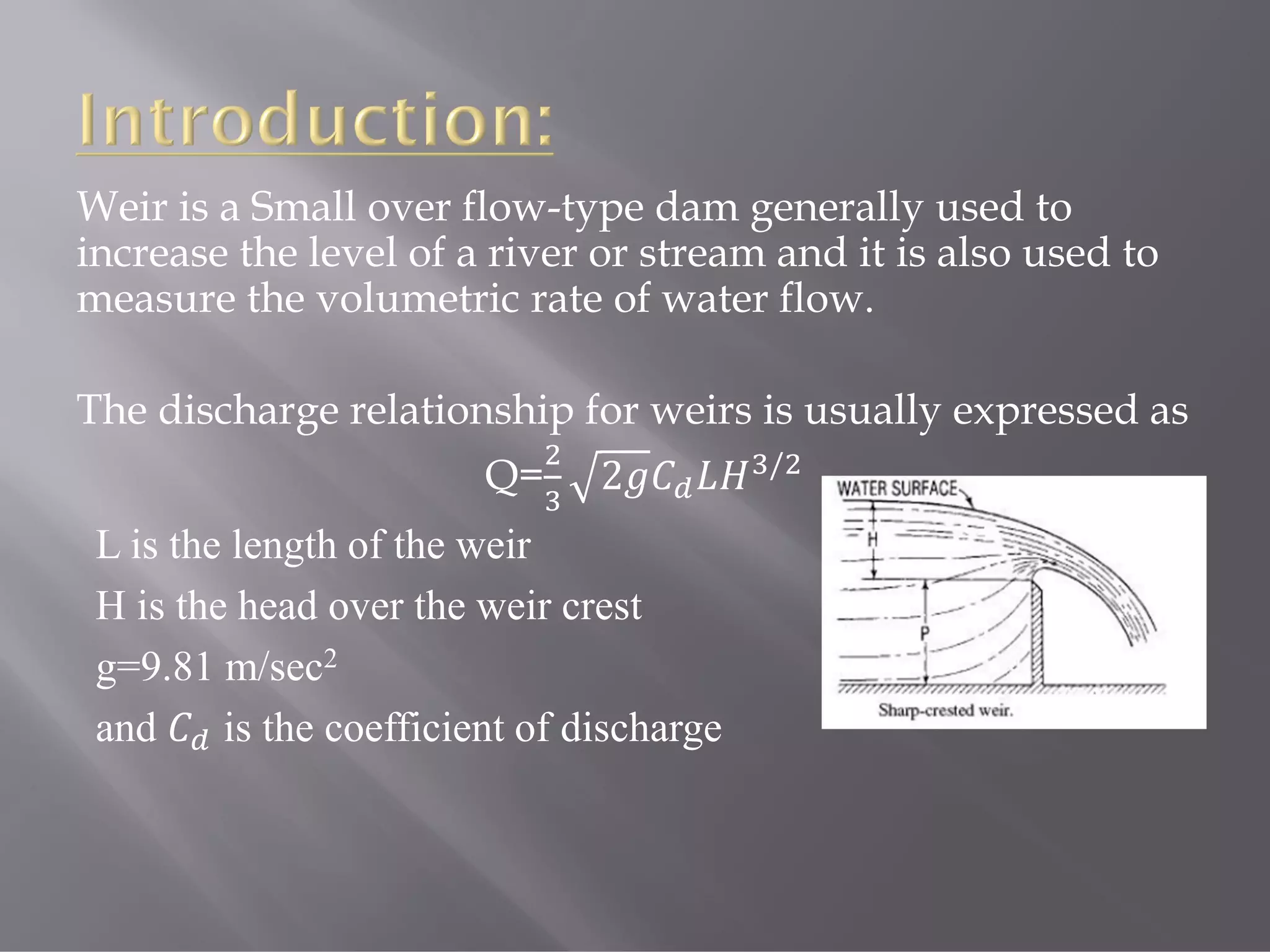
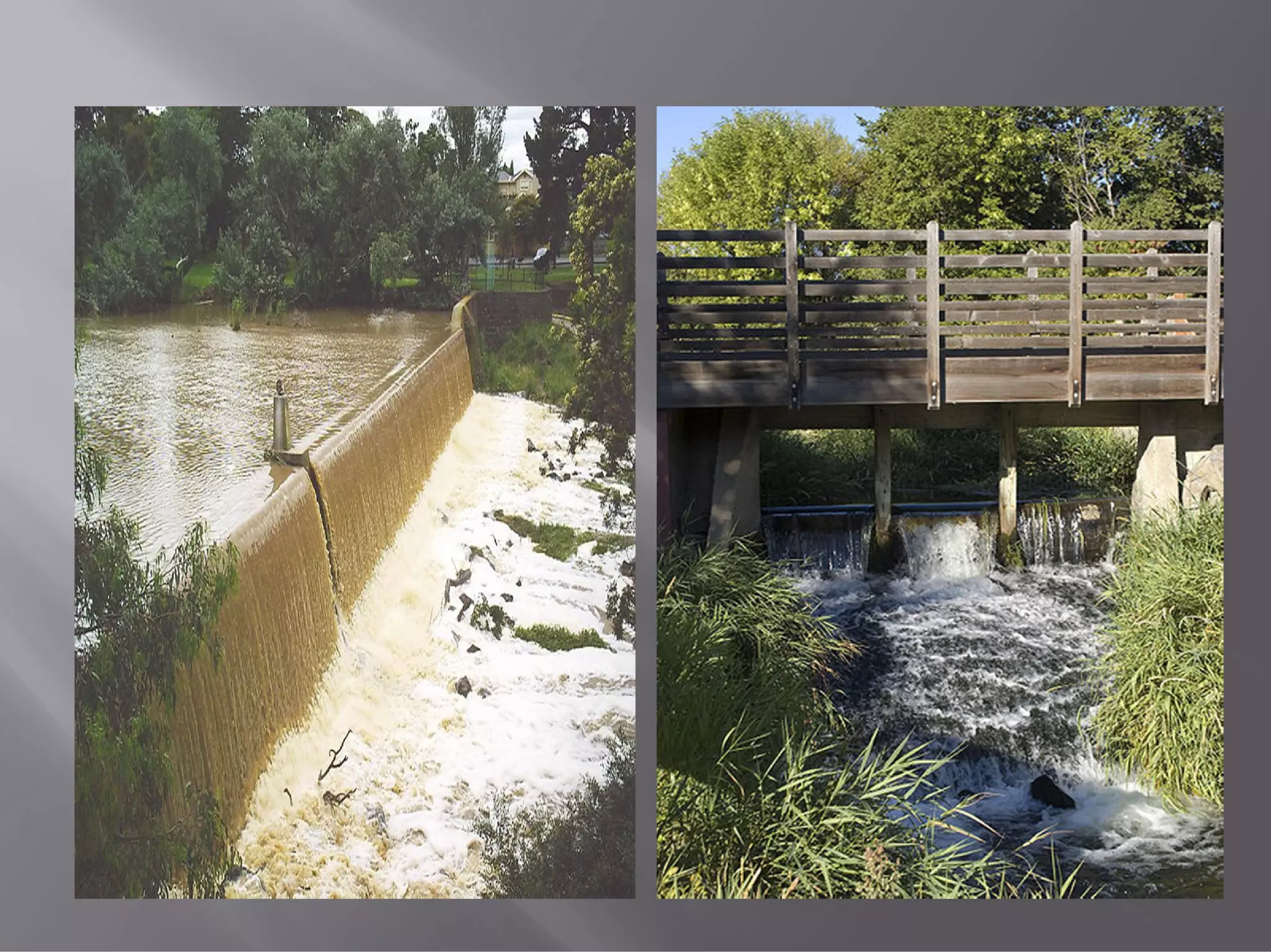
Explains weirs as small overflow dams, measuring water flow, with discharge formula Q=2.
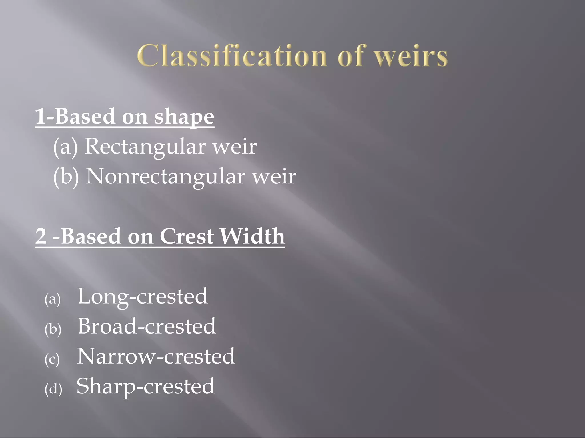
Categorizes weirs by shape (rectangular, non-rectangular) and width (long, broad, narrow, sharp).
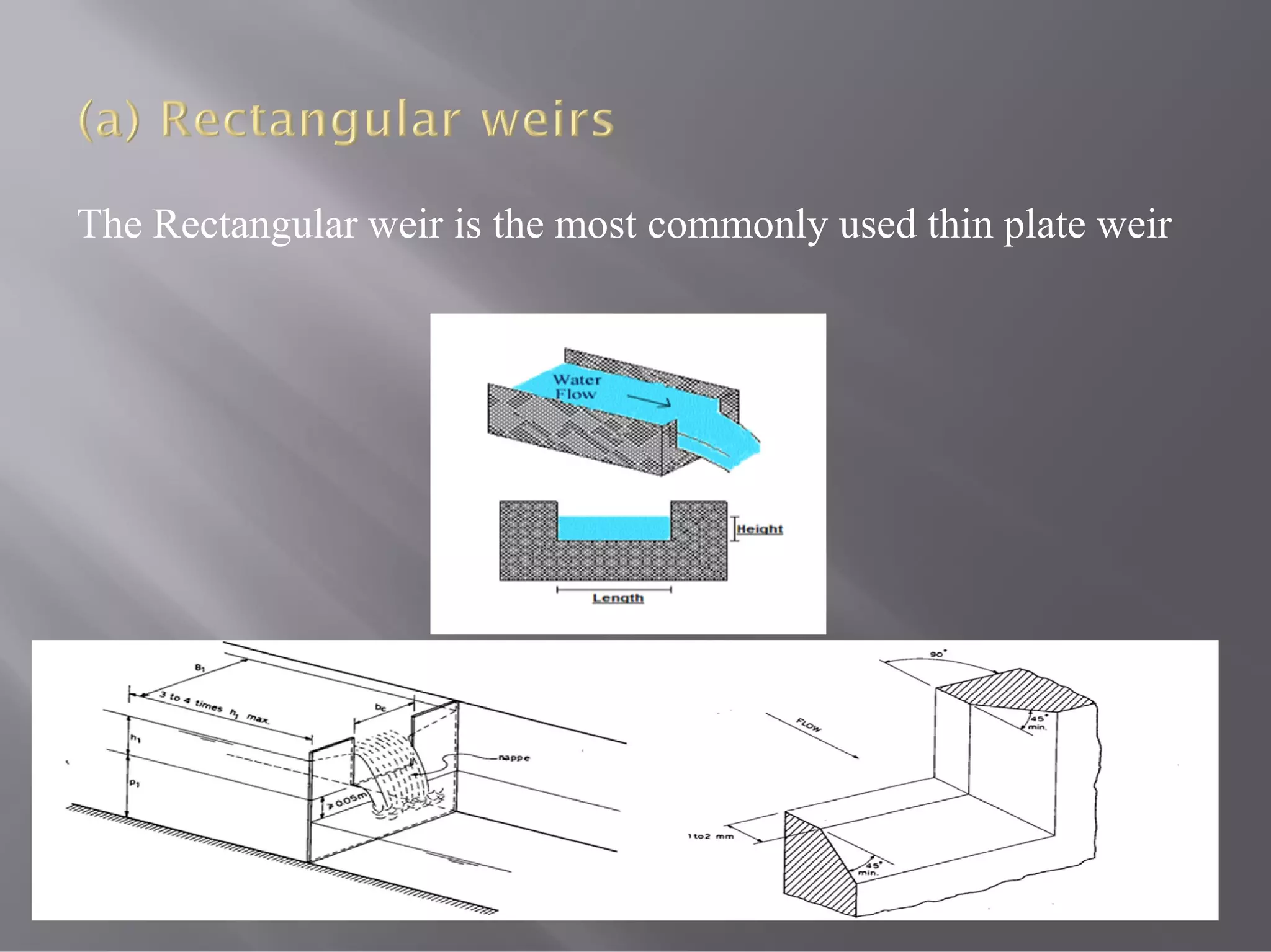
Details rectangular and triangular weirs, and highlights rectangular weir as the most common type.
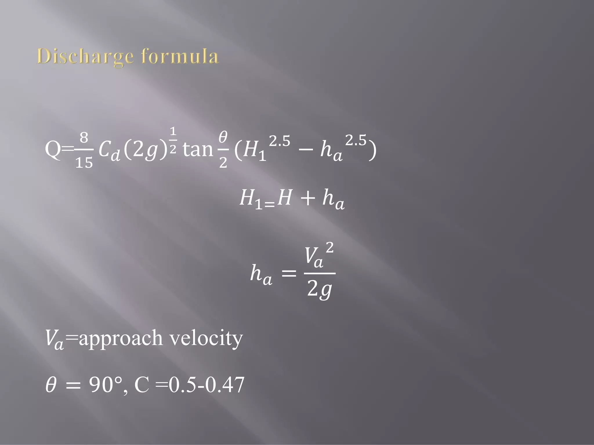
Discusses discharge equations for various weir types: triangular, trapezoidal, etc.
Describes unique weir designs including parabolic, circular, and Cipolletti weirs.
Outlines basics of measuring flow with weirs and introduces proportional weirs.Explains linear, quadratic, logarithmic, and exponential weirs with respective discharge equations.Describes innovative designs like baseless weirs, labyrinth, and Piano Key Weirs for enhanced capacity.
Expresses gratitude to the audience, wrapping up the presentation.
Weir is aSmall over flow-type dam generally used to
increase the level of a river or stream and it is also used to
measure the volumetric rate of water flow.
The discharge relationship for weirs is usually expressed as
Q= 2 /
L is the length of the weir
H is the head over the weir crest
g=9.81 m/sec2
and is the coefficient of discharge
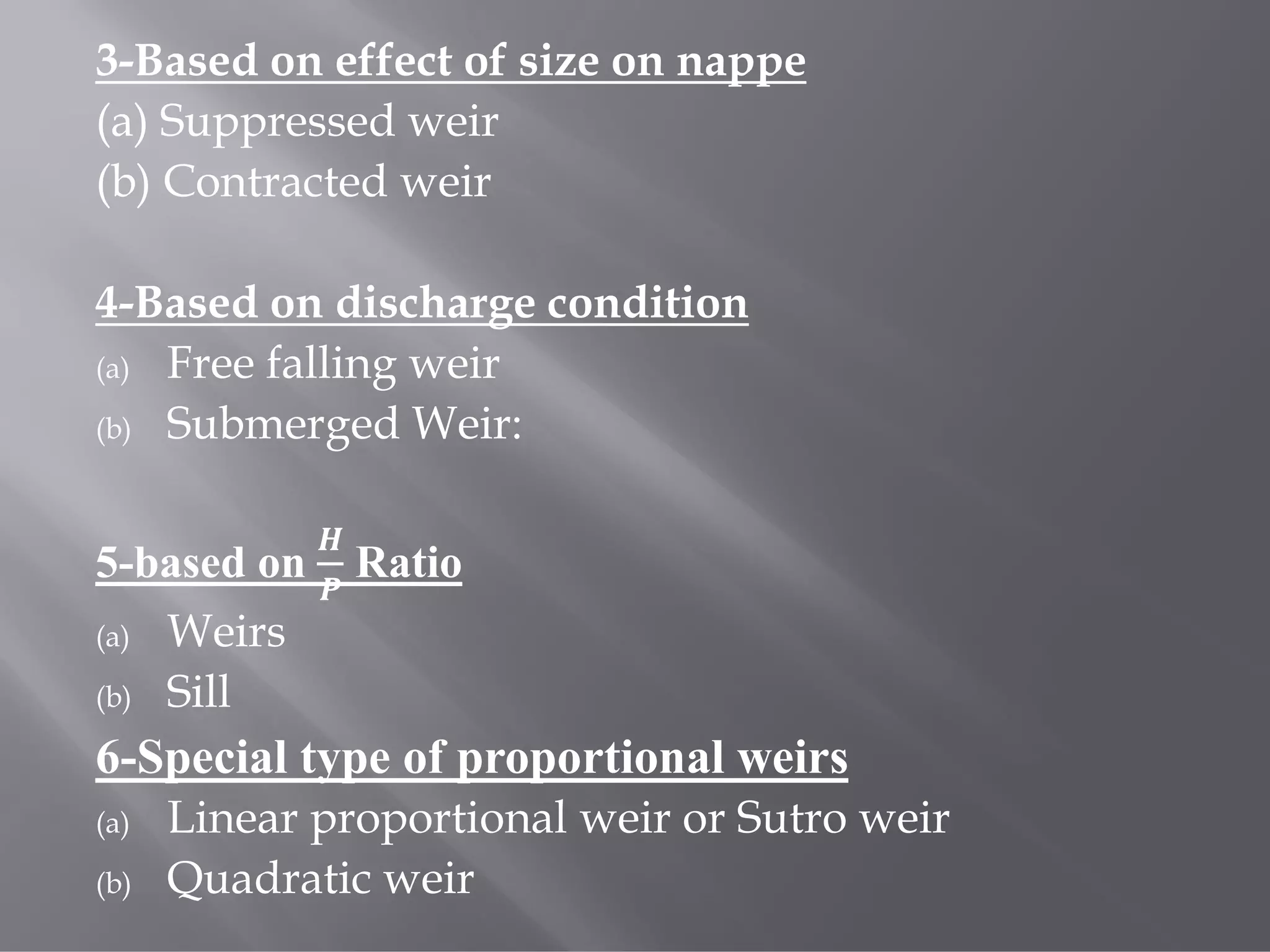
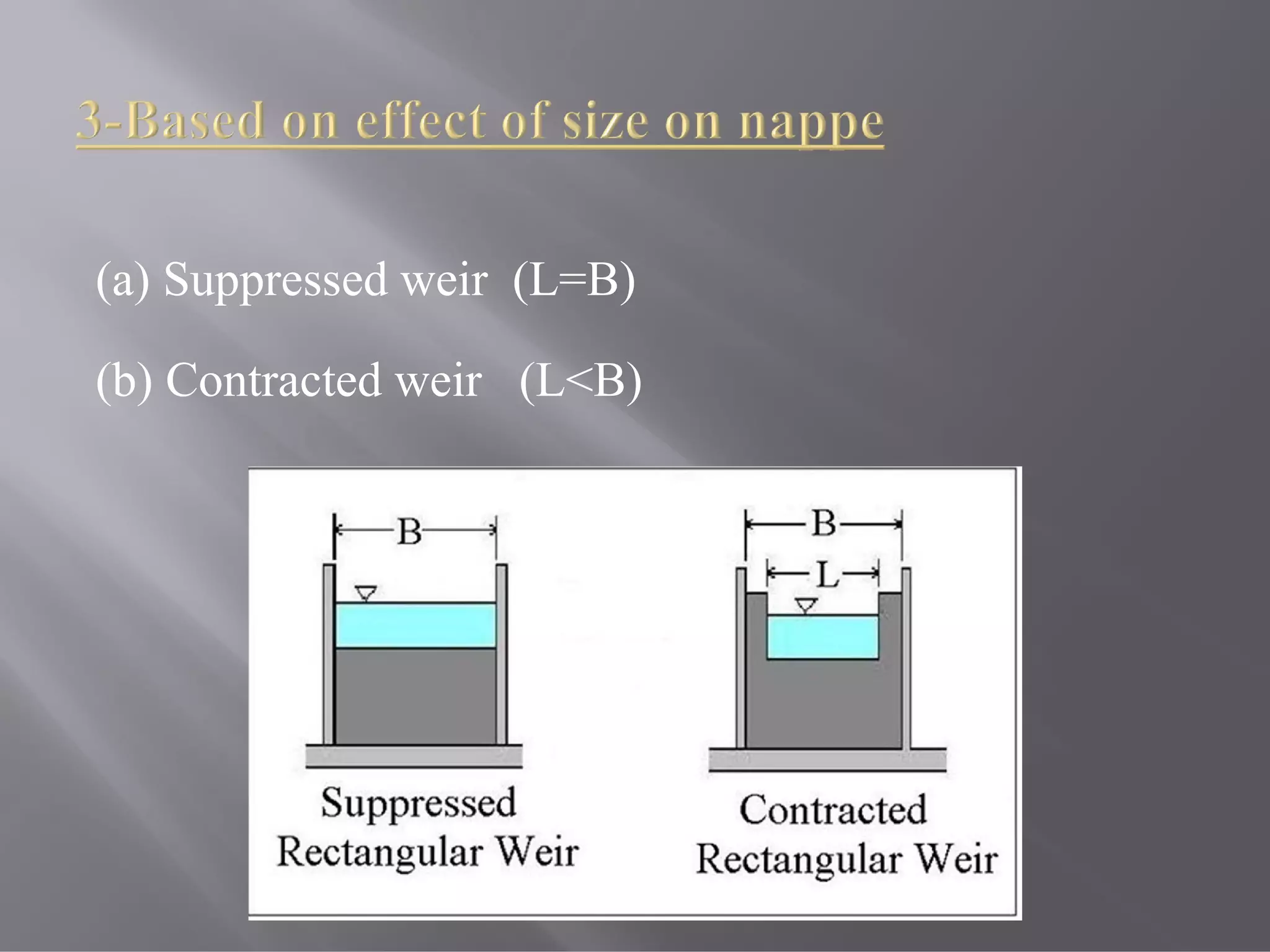
3-Based on effectof size on nappe
(a) Suppressed weir
(b) Contracted weir
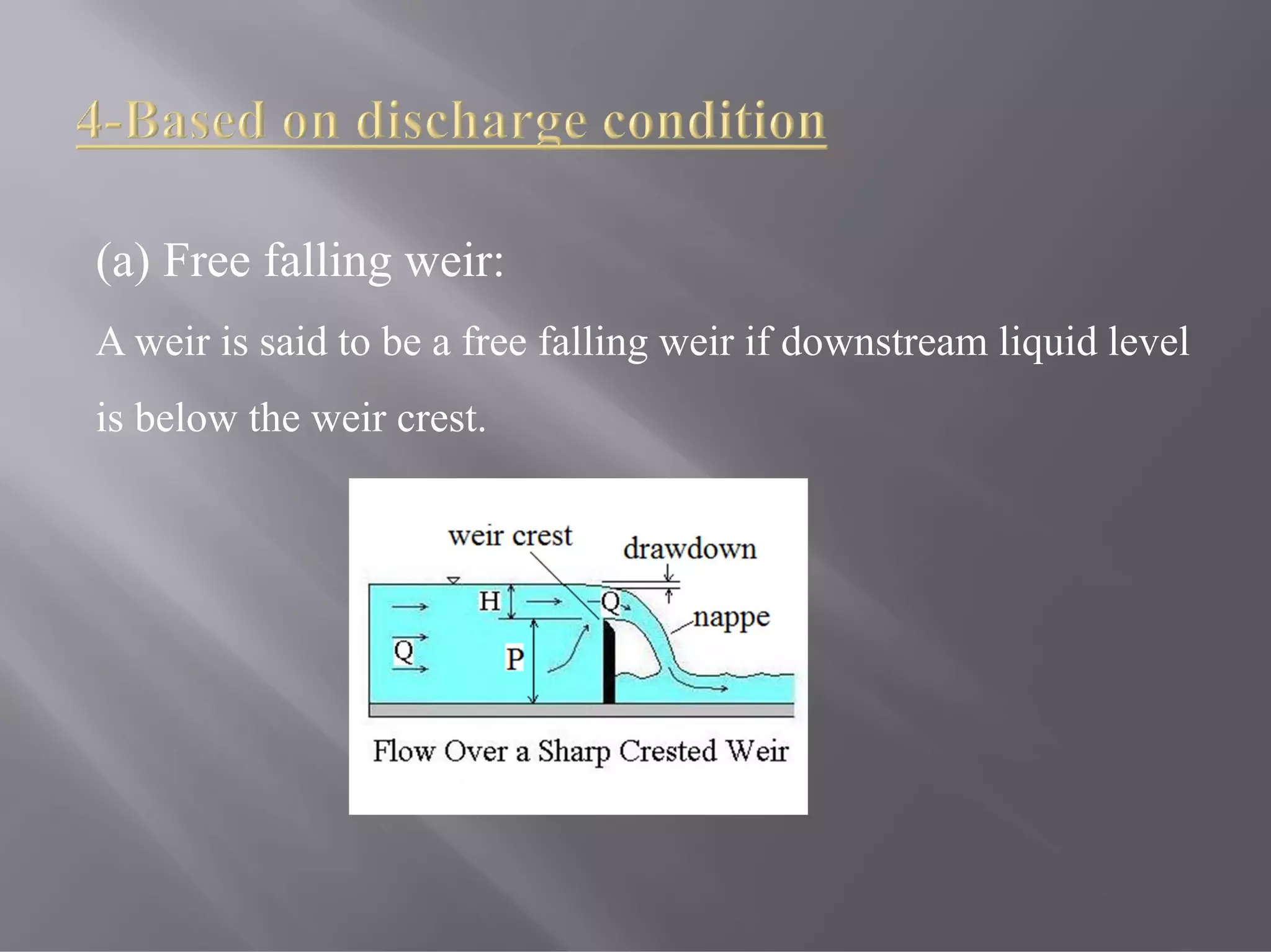
4-Based on discharge condition
(a) Free falling weir
(b) Submerged Weir:
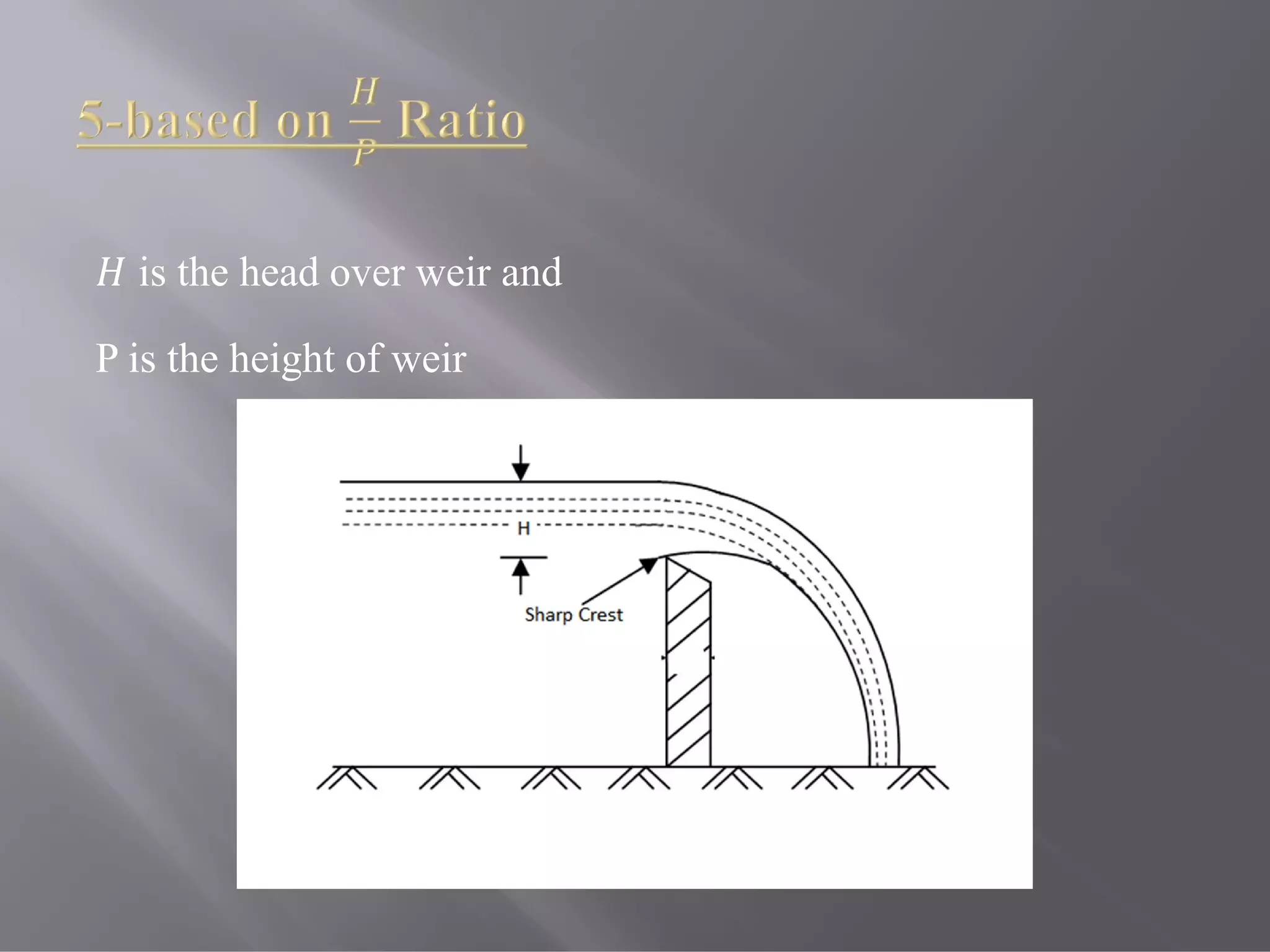
5-based on Ratio
(a) Weirs
(b) Sill
6-Special type of proportional weirs
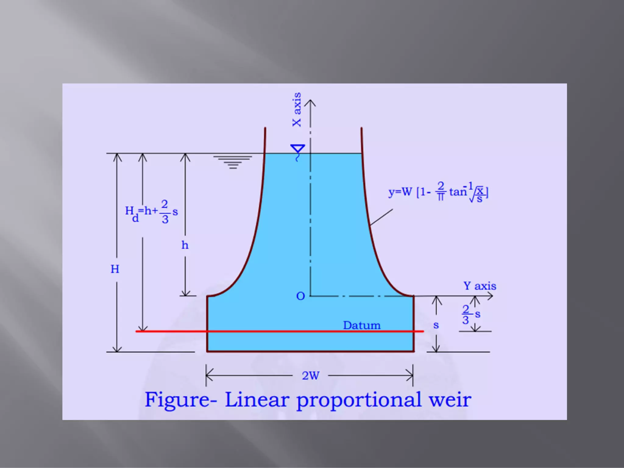
(a) Linear proportional weir or Sutro weir
(b) Quadratic weir
6.
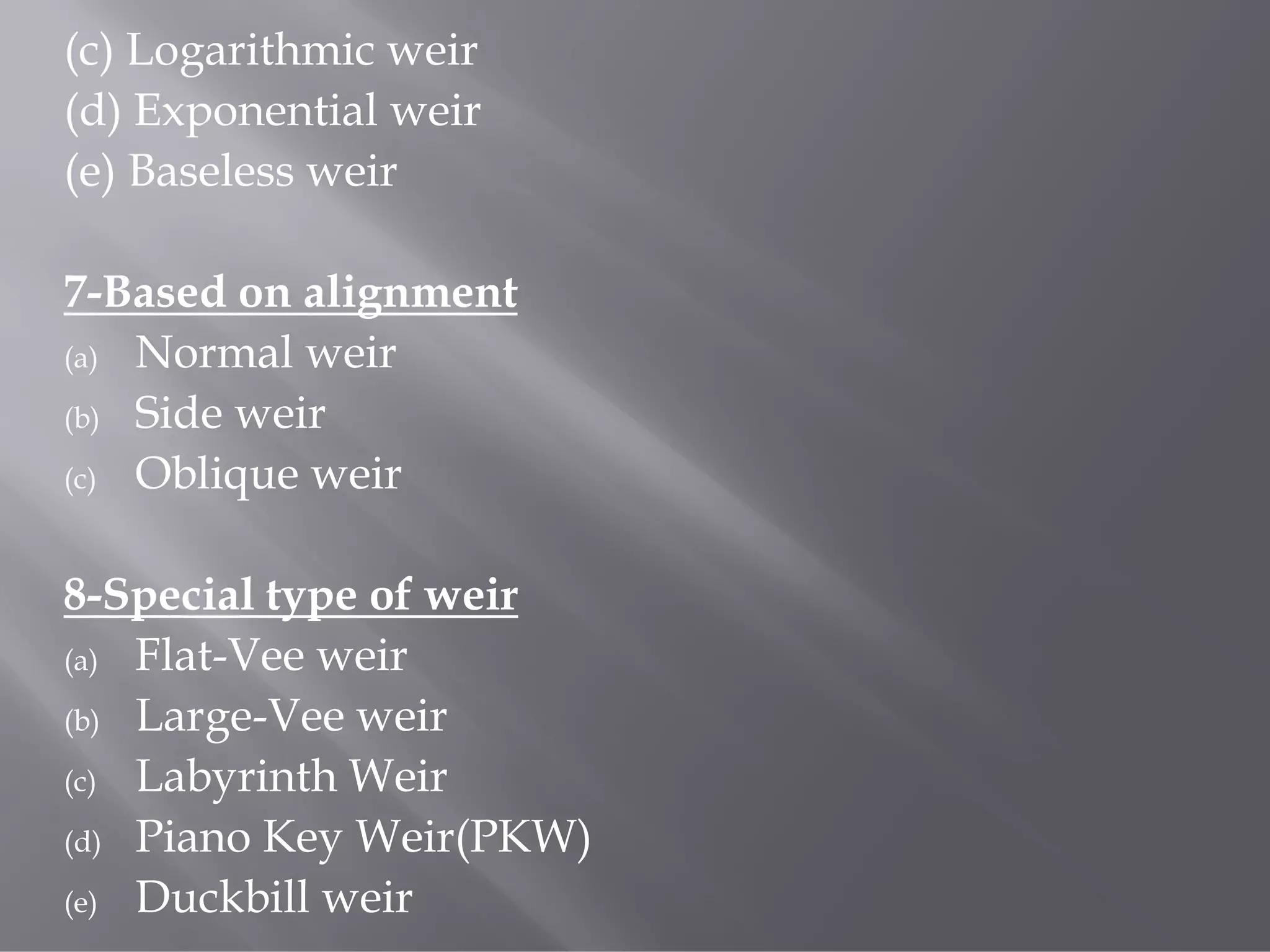
(c) Logarithmic weir
(d)Exponential weir
(e) Baseless weir
7-Based on alignment
(a) Normal weir
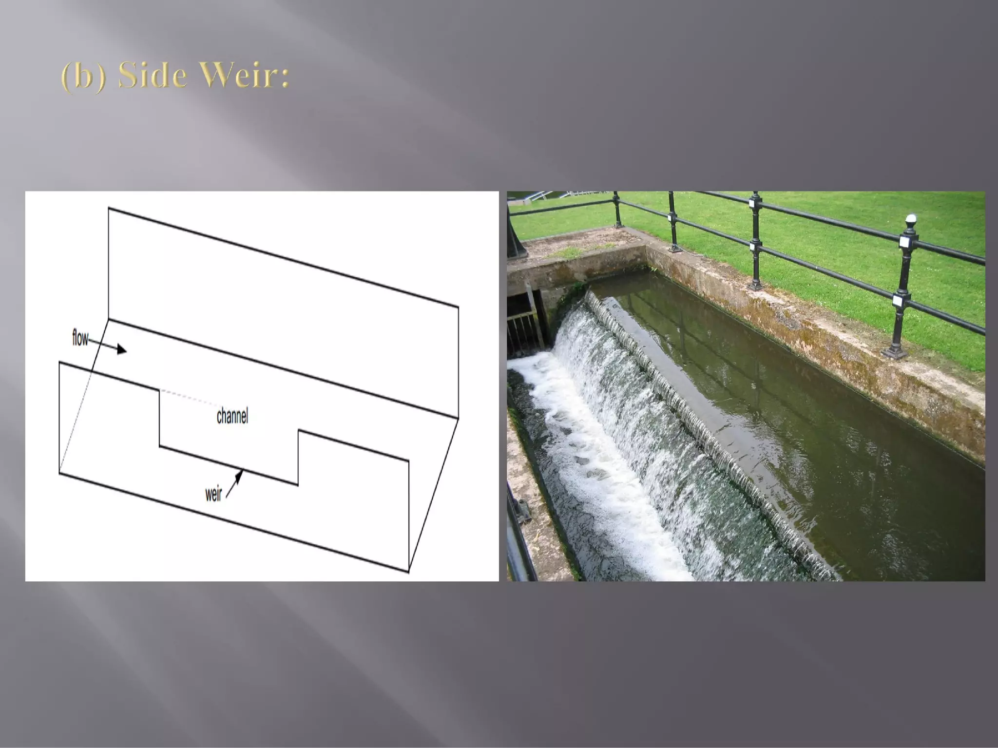
(b) Side weir
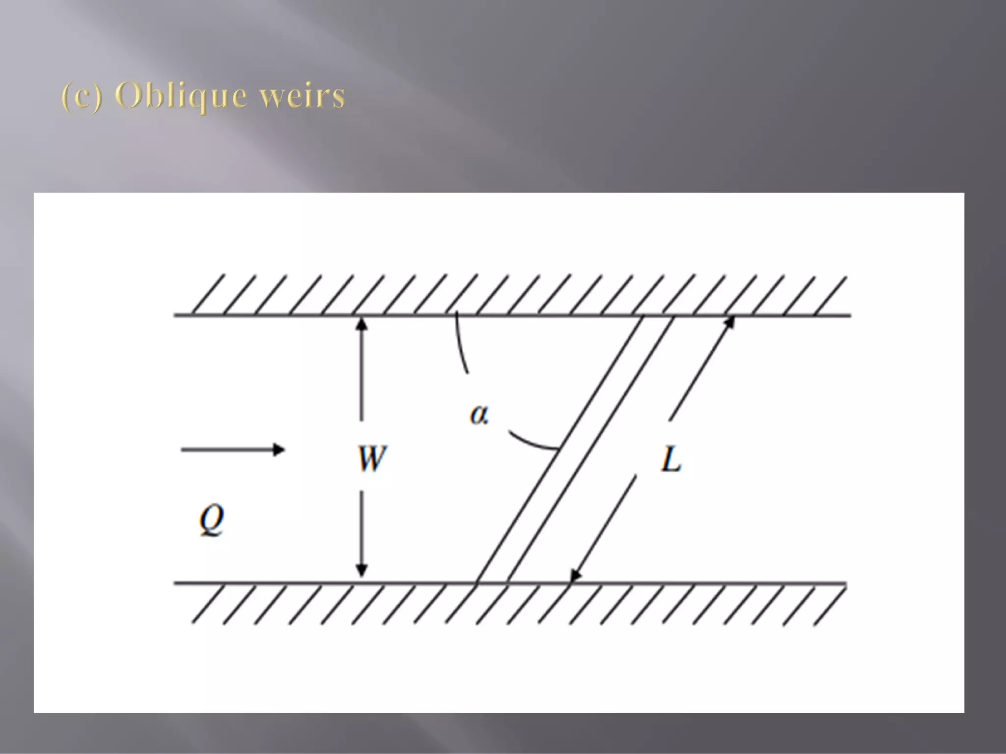
(c) Oblique weir
8-Special type of weir
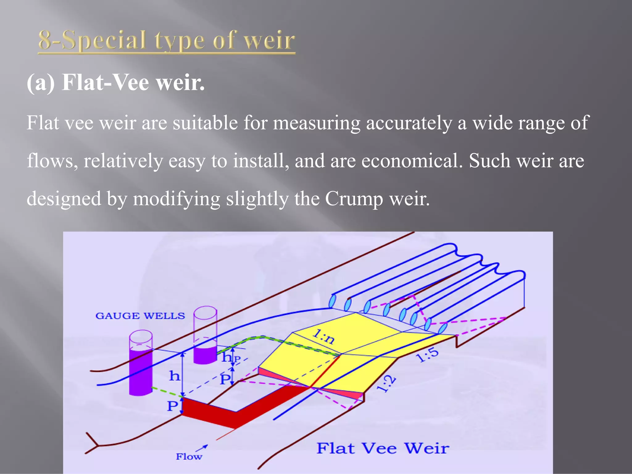
(a) Flat-Vee weir
(b) Large-Vee weir
(c) Labyrinth Weir
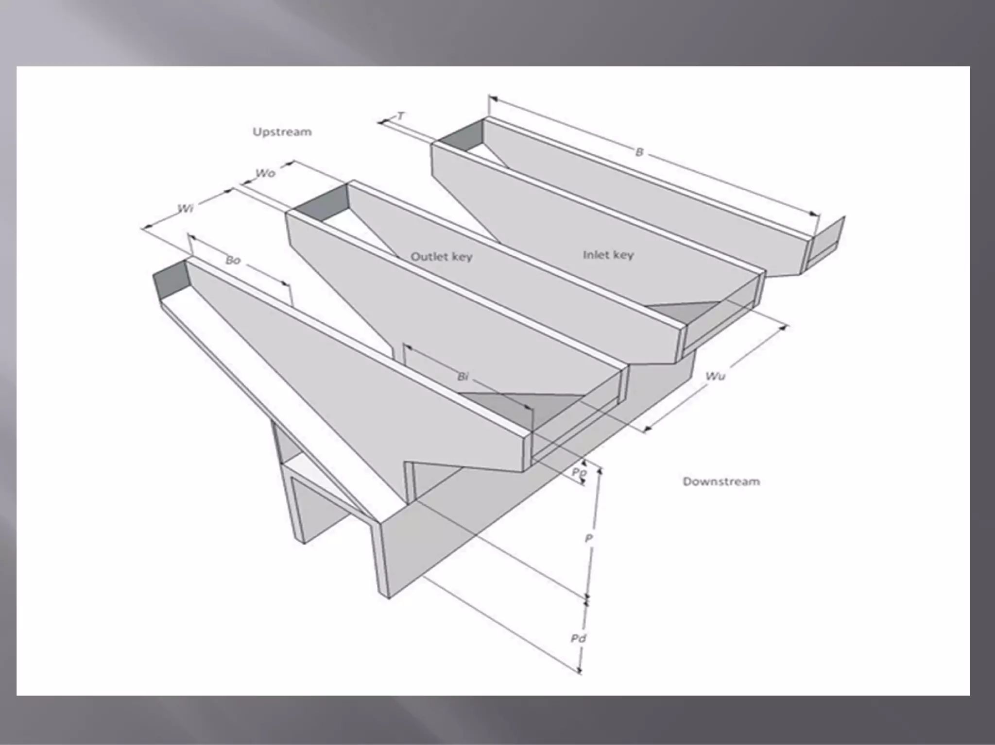
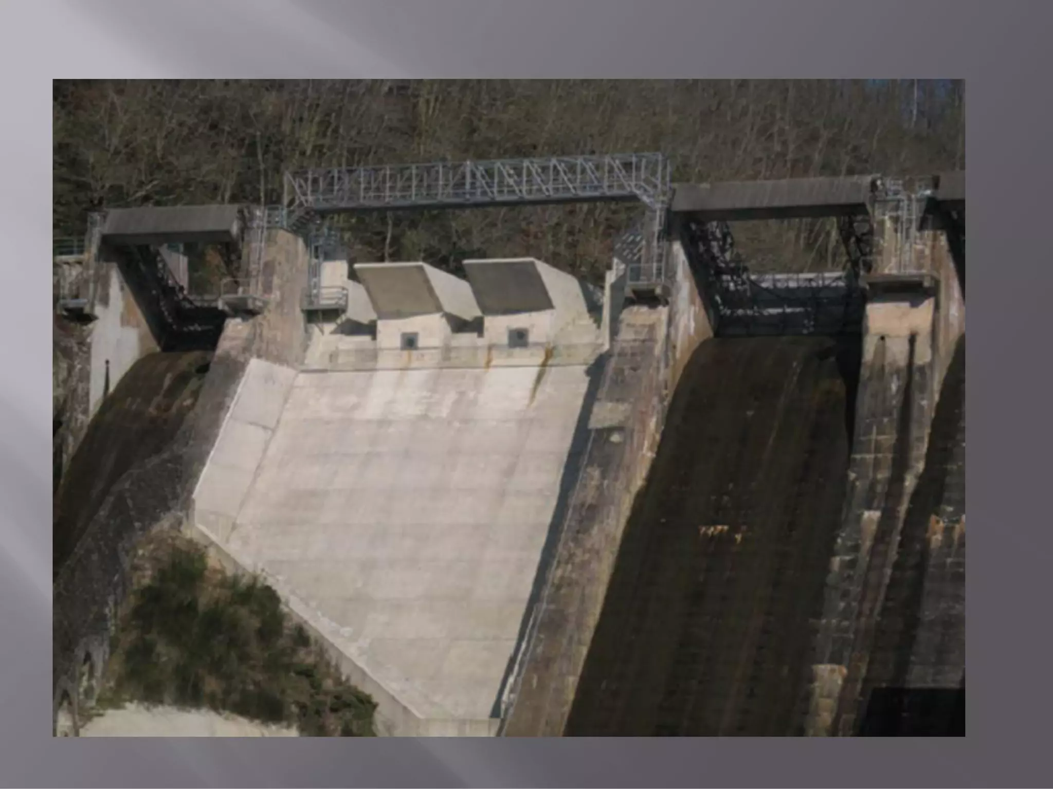
(d) Piano Key Weir(PKW)
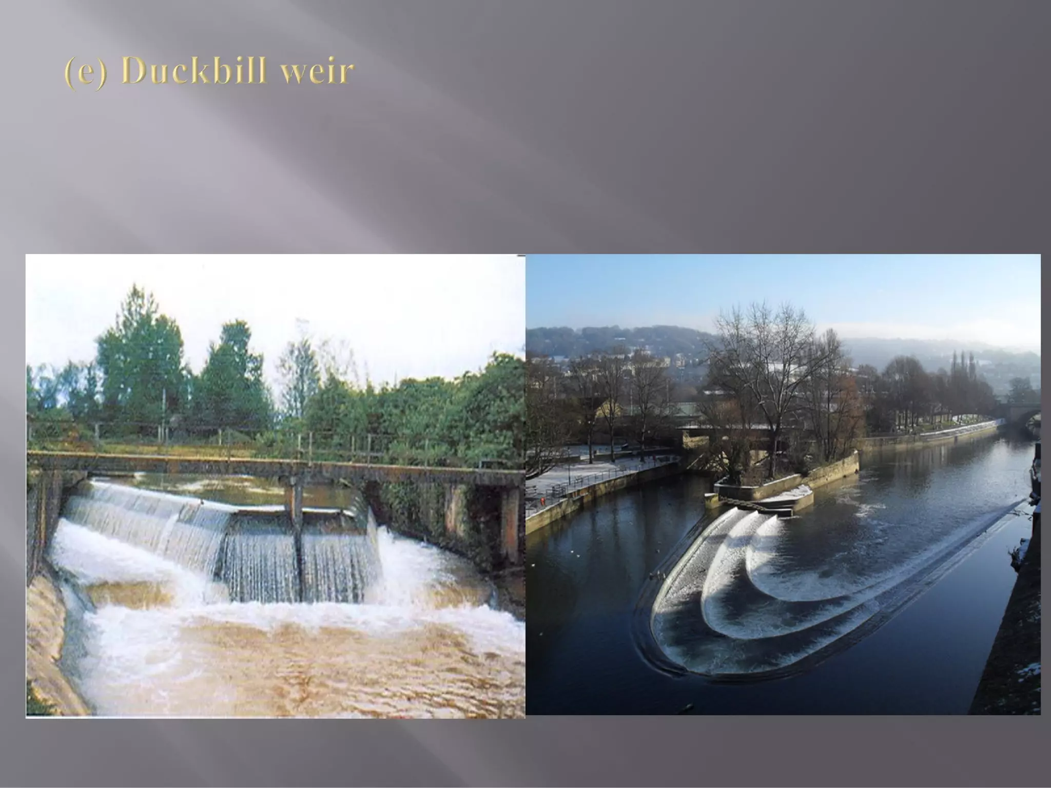
(e) Duckbill weir
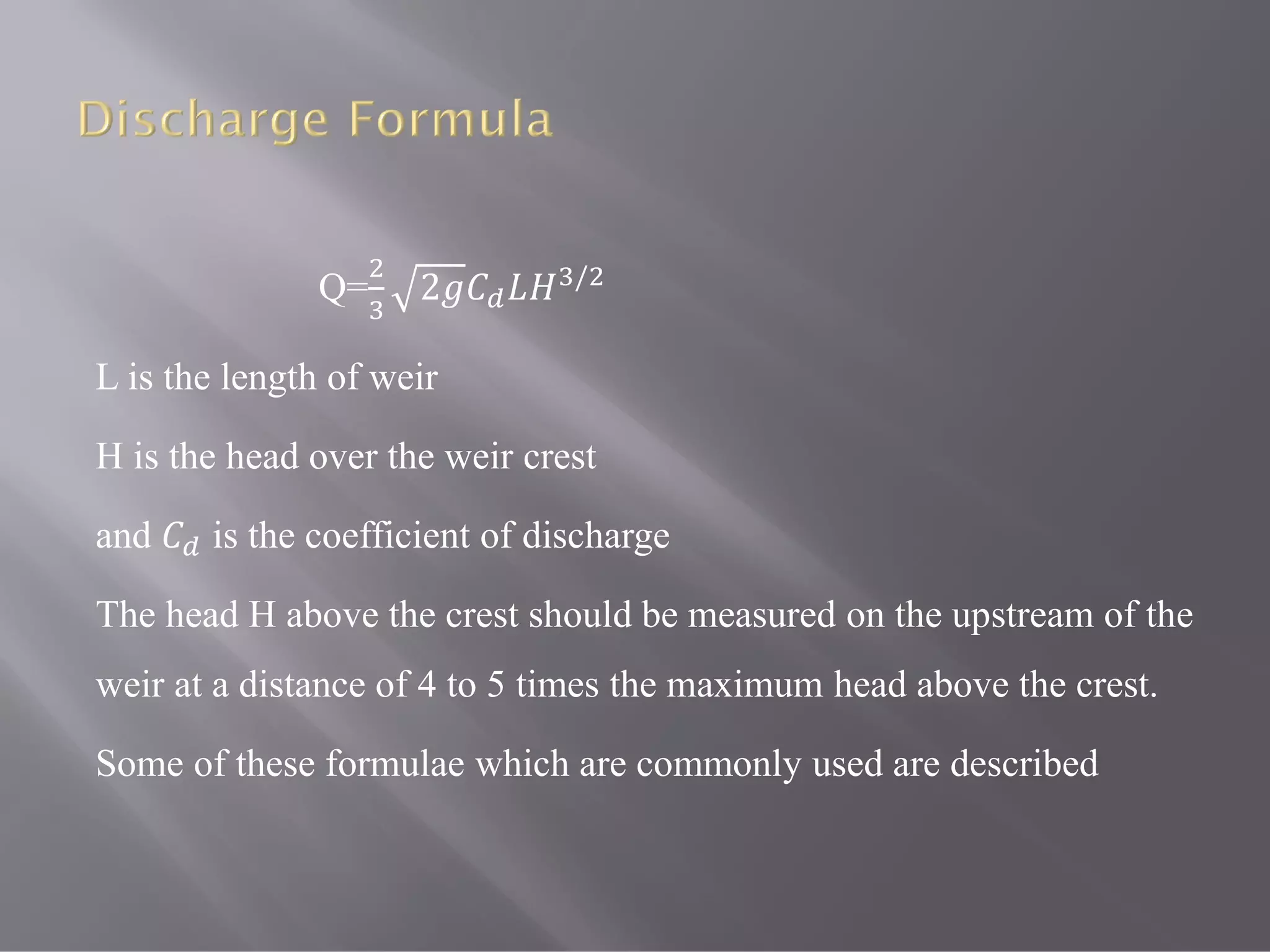
Q= 2 /
Lis the length of weir
H is the head over the weir crest
and is the coefficient of discharge
The head H above the crest should be measured on the upstream of the
weir at a distance of 4 to 5 times the maximum head above the crest.
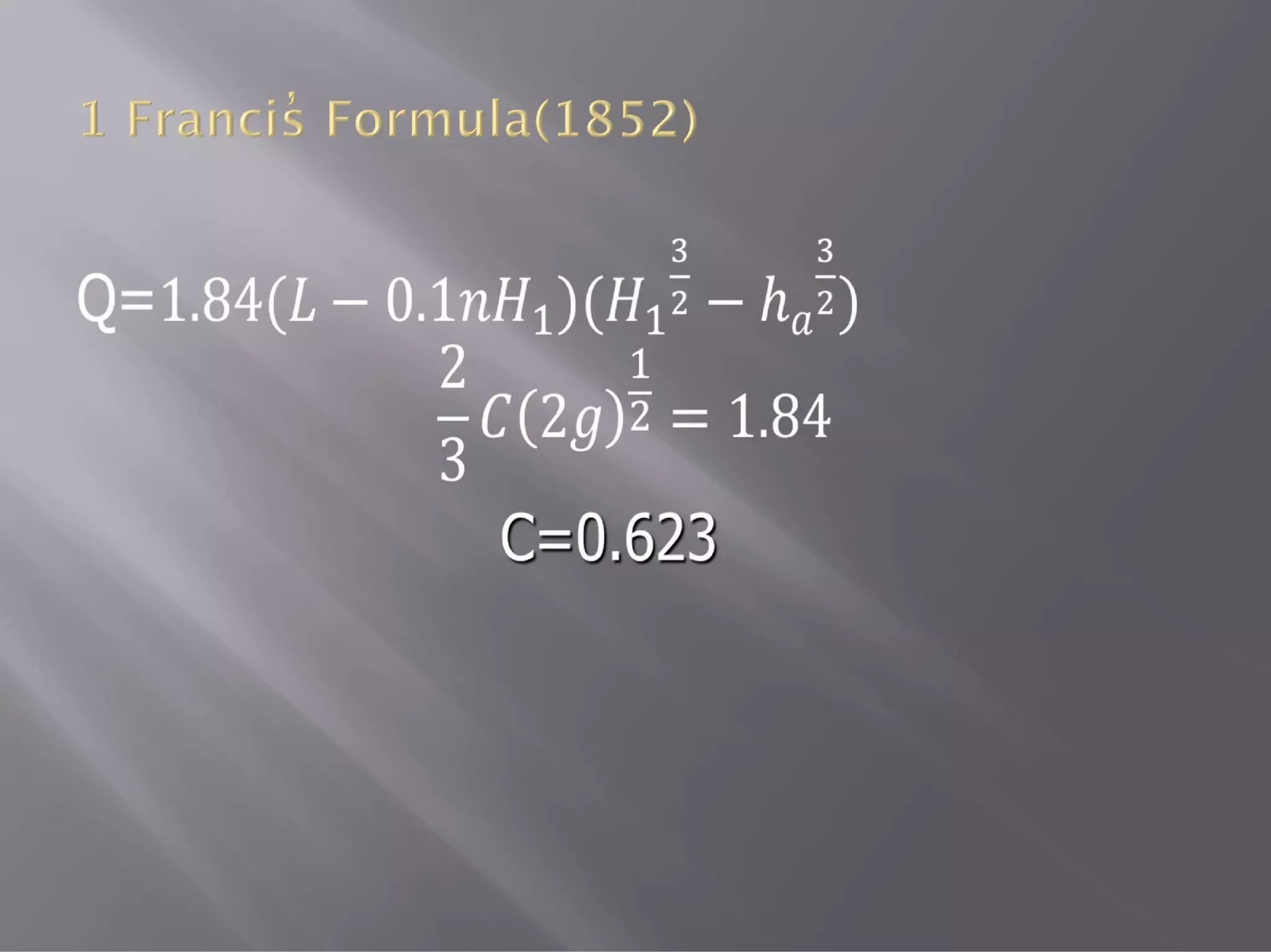
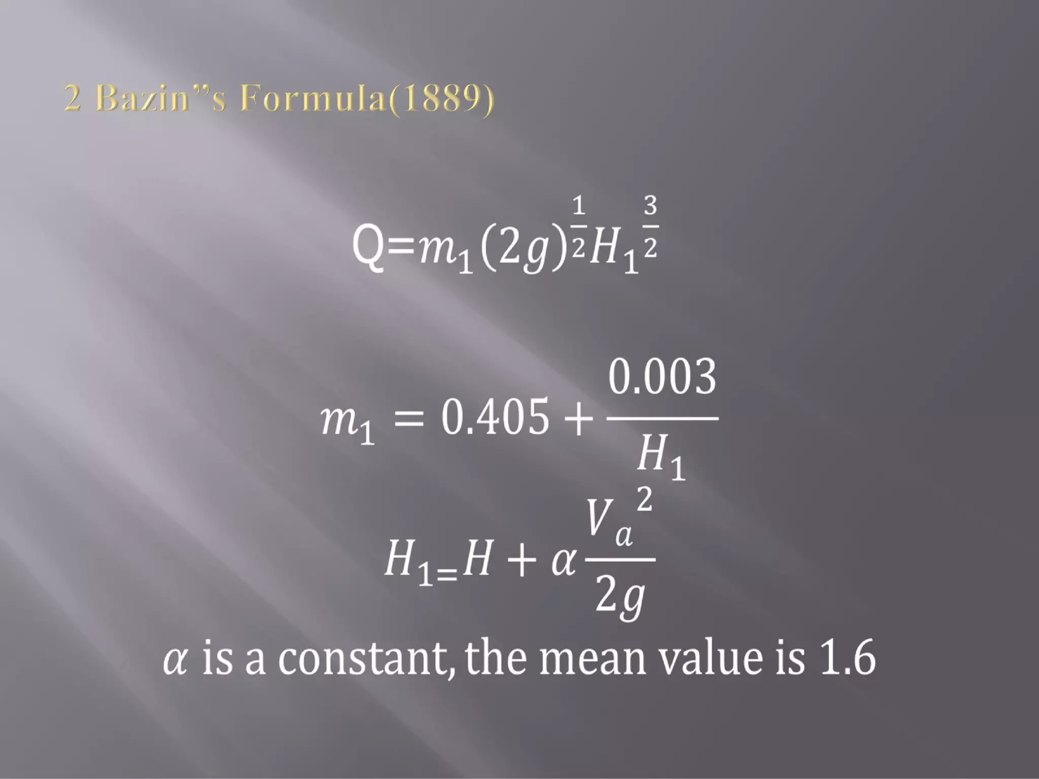
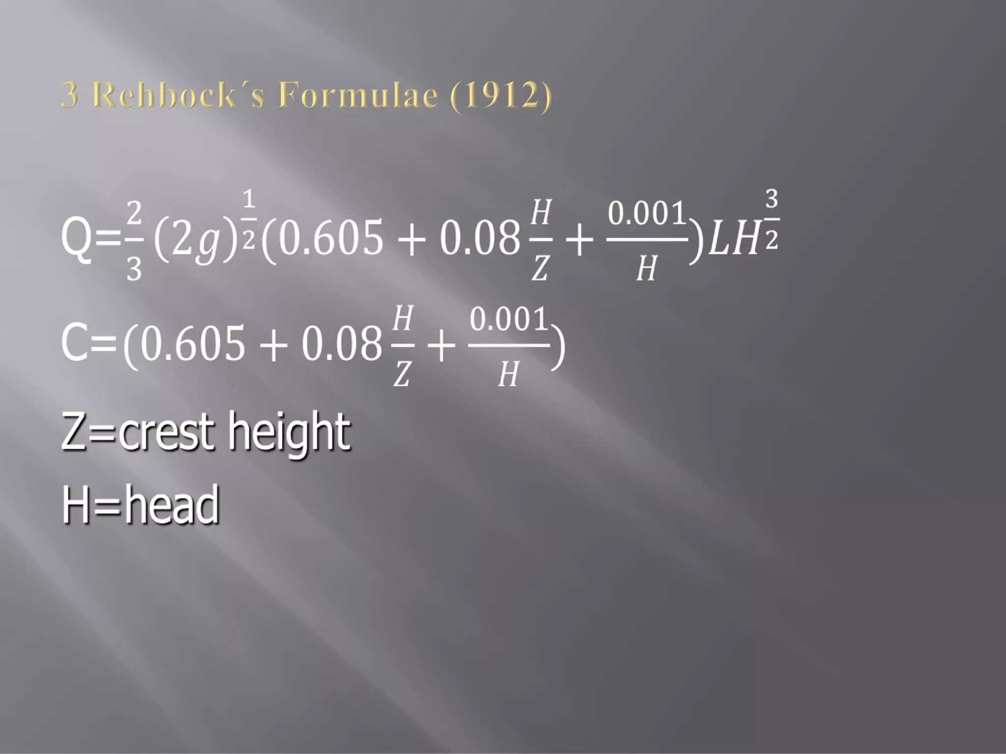
Some of these formulae which are commonly used are described
13.
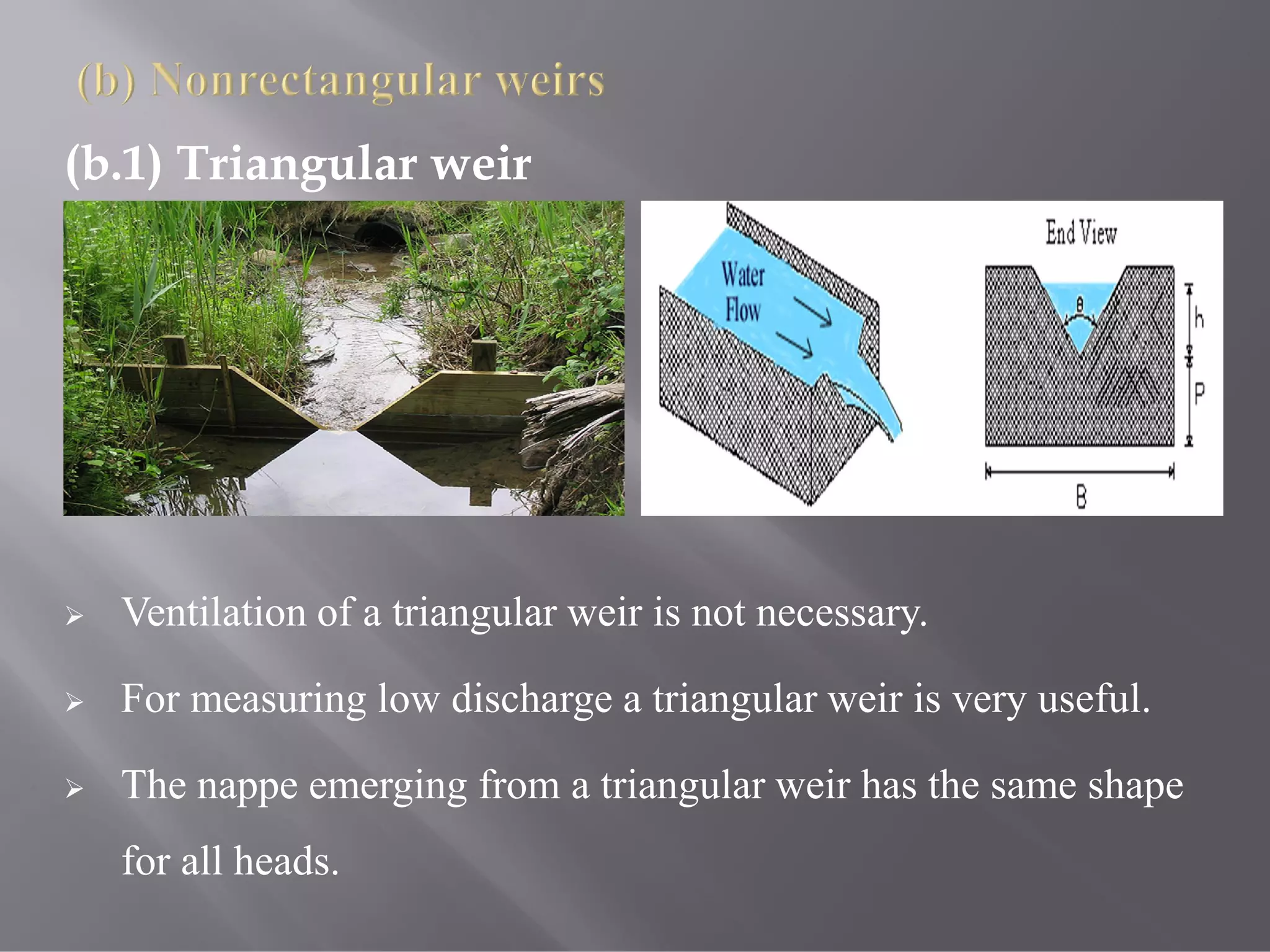
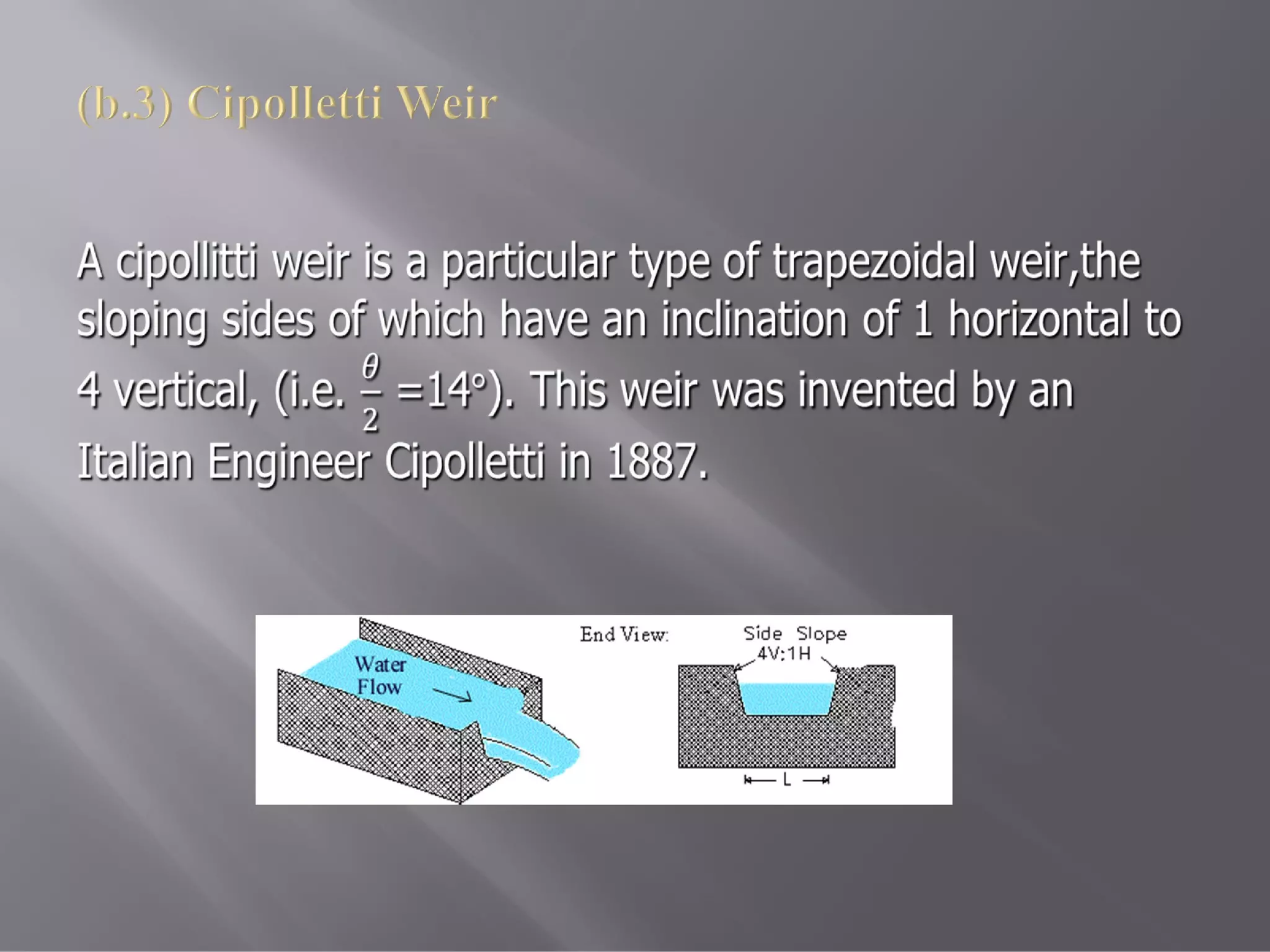
(b.1) Triangular weir
Ventilation of a triangular weir is not necessary.
For measuring low discharge a triangular weir is very useful.
The nappe emerging from a triangular weir has the same shape
for all heads.
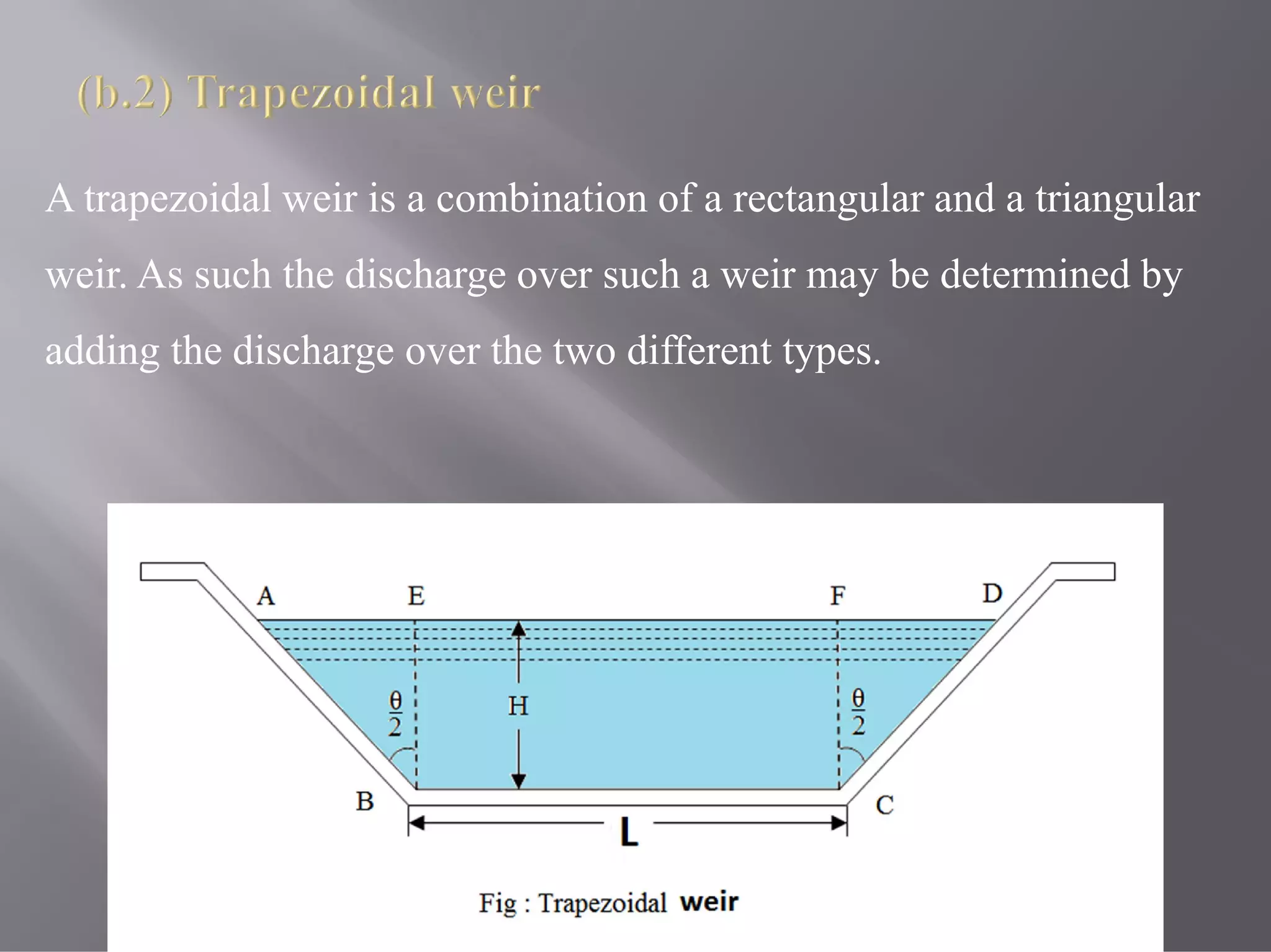
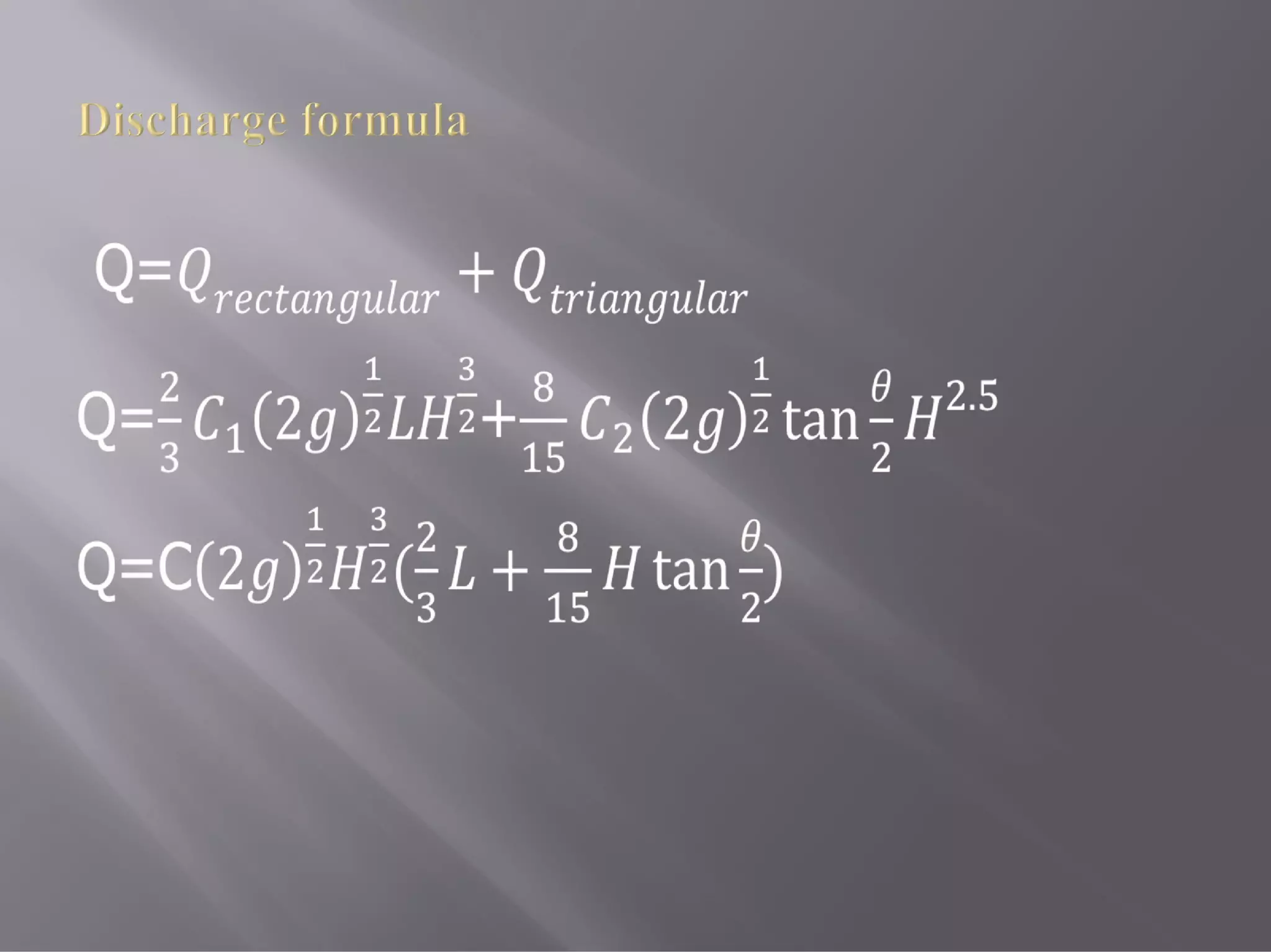
A trapezoidal weiris a combination of a rectangular and a triangular
weir. As such the discharge over such a weir may be determined by
adding the discharge over the two different types.
18.
Q= 2 /
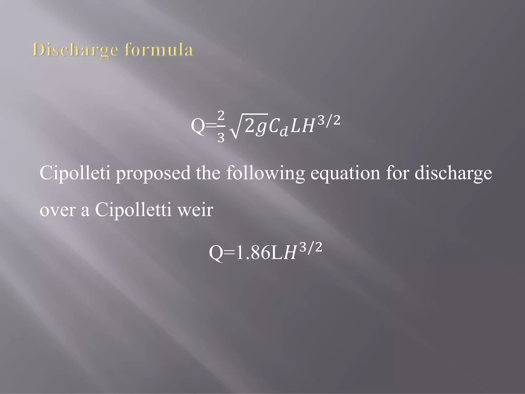
Cipolletiproposed the following equation for discharge
over a Cipolletti weir
Q=1.86L /
19.
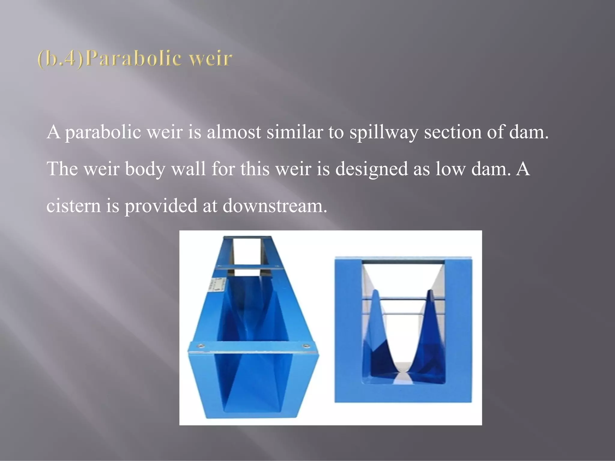
A parabolic weiris almost similar to spillway section of dam.
The weir body wall for this weir is designed as low dam. A
cistern is provided at downstream.
20.
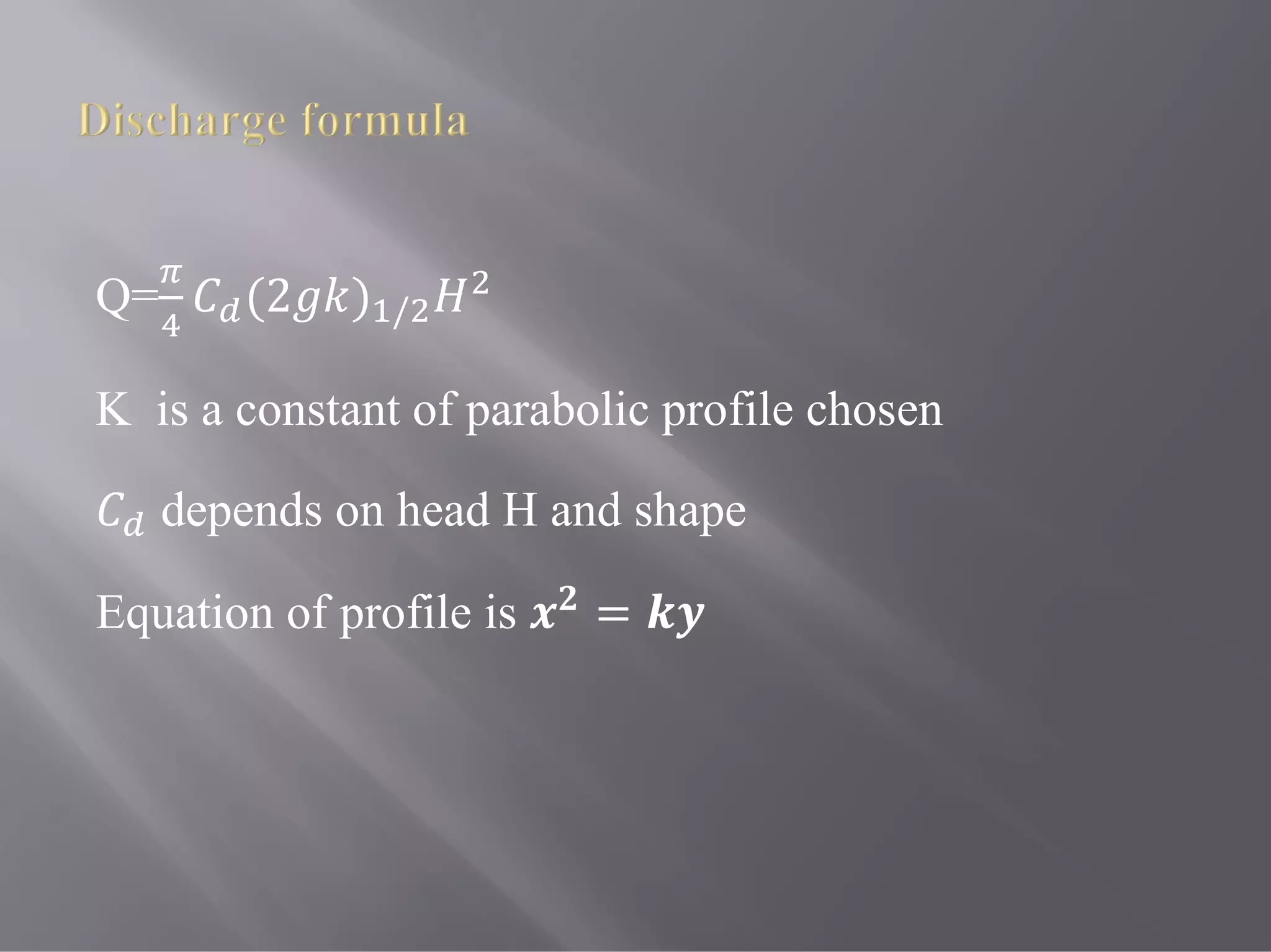
Q= (2 )/
K is a constant of parabolic profile chosen
depends on head H and shape
Equation of profile is =
21.
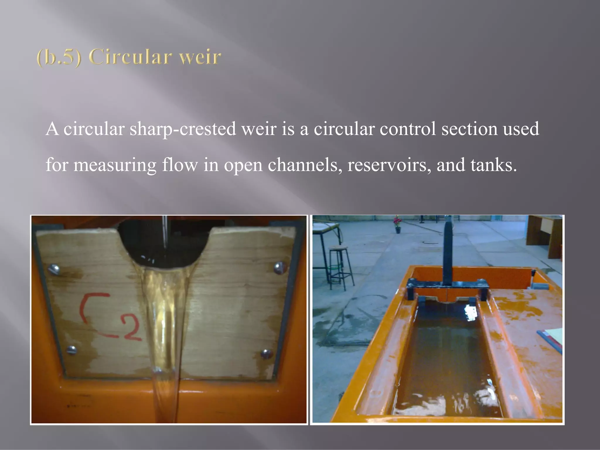
A circular sharp-crestedweir is a circular control section used
for measuring flow in open channels, reservoirs, and tanks.
22.
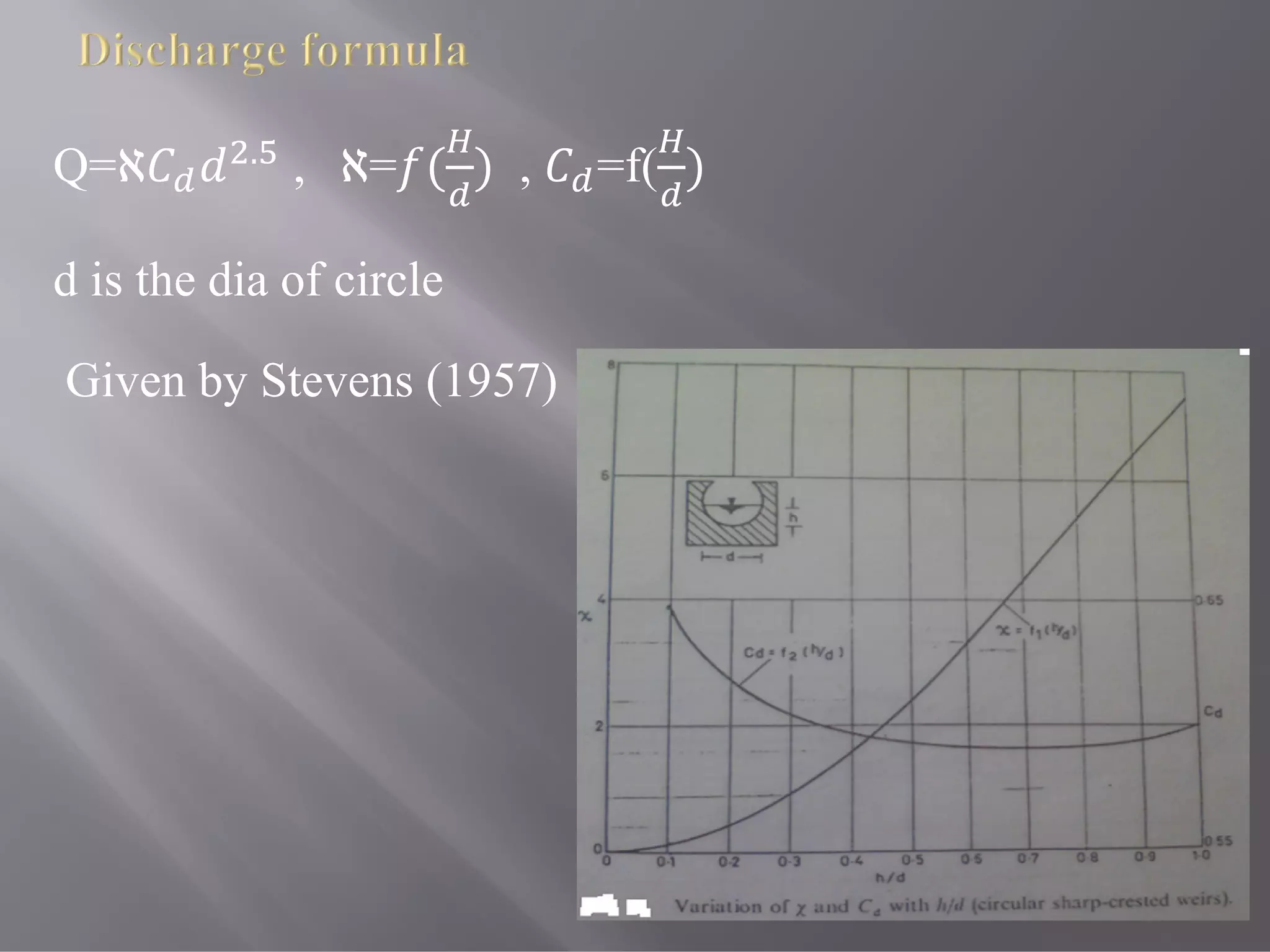
Q=ℵ .
, ℵ=( ) , =f( )
d is the dia of circle
Given by Stevens (1957)
24.
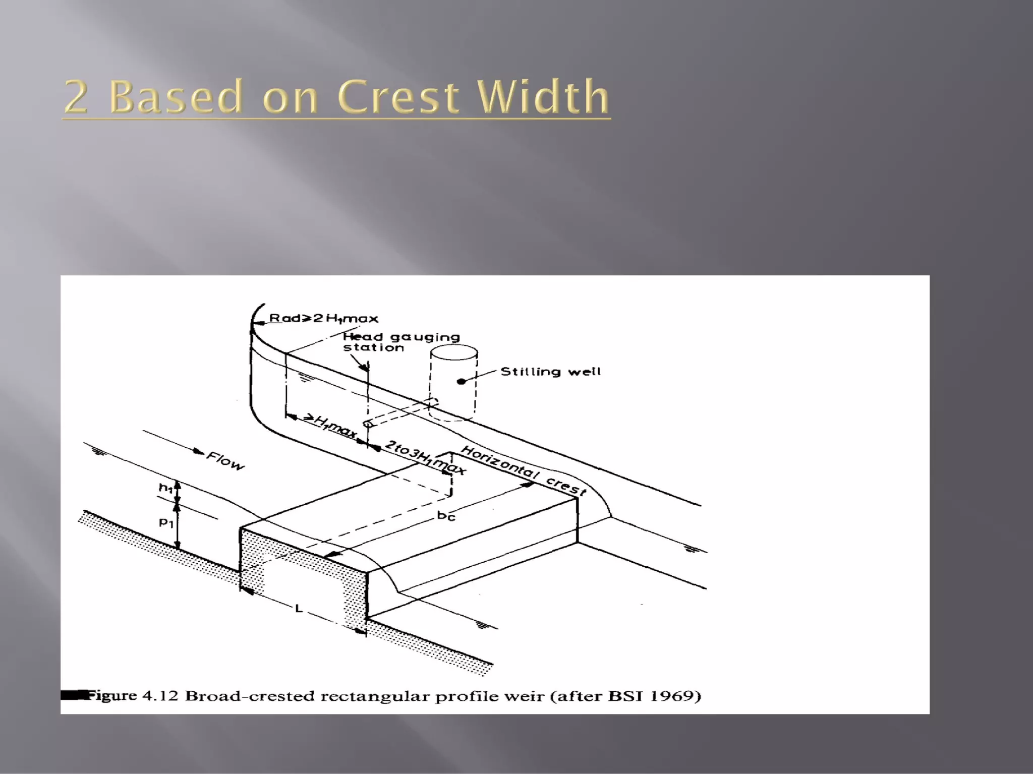
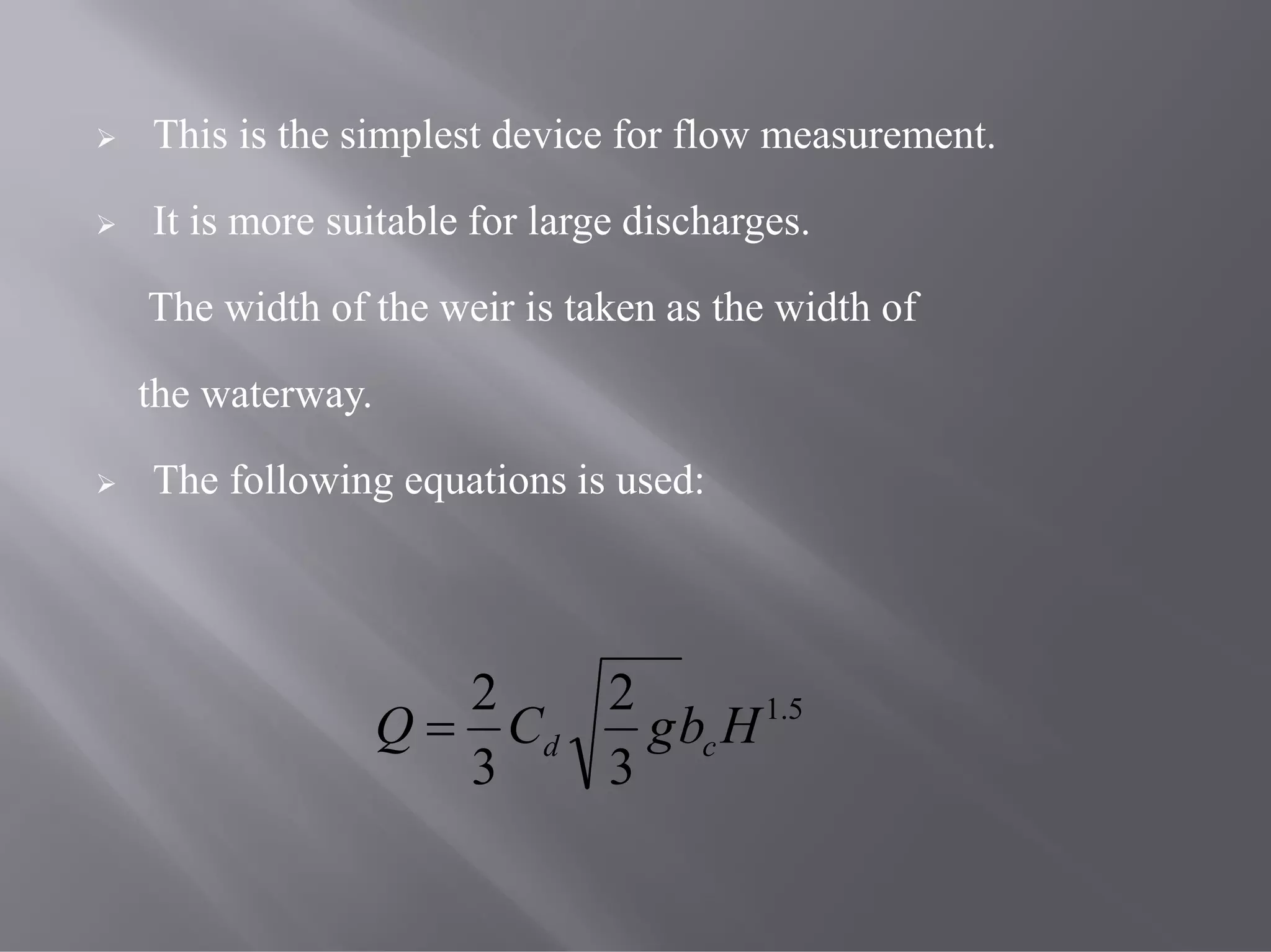
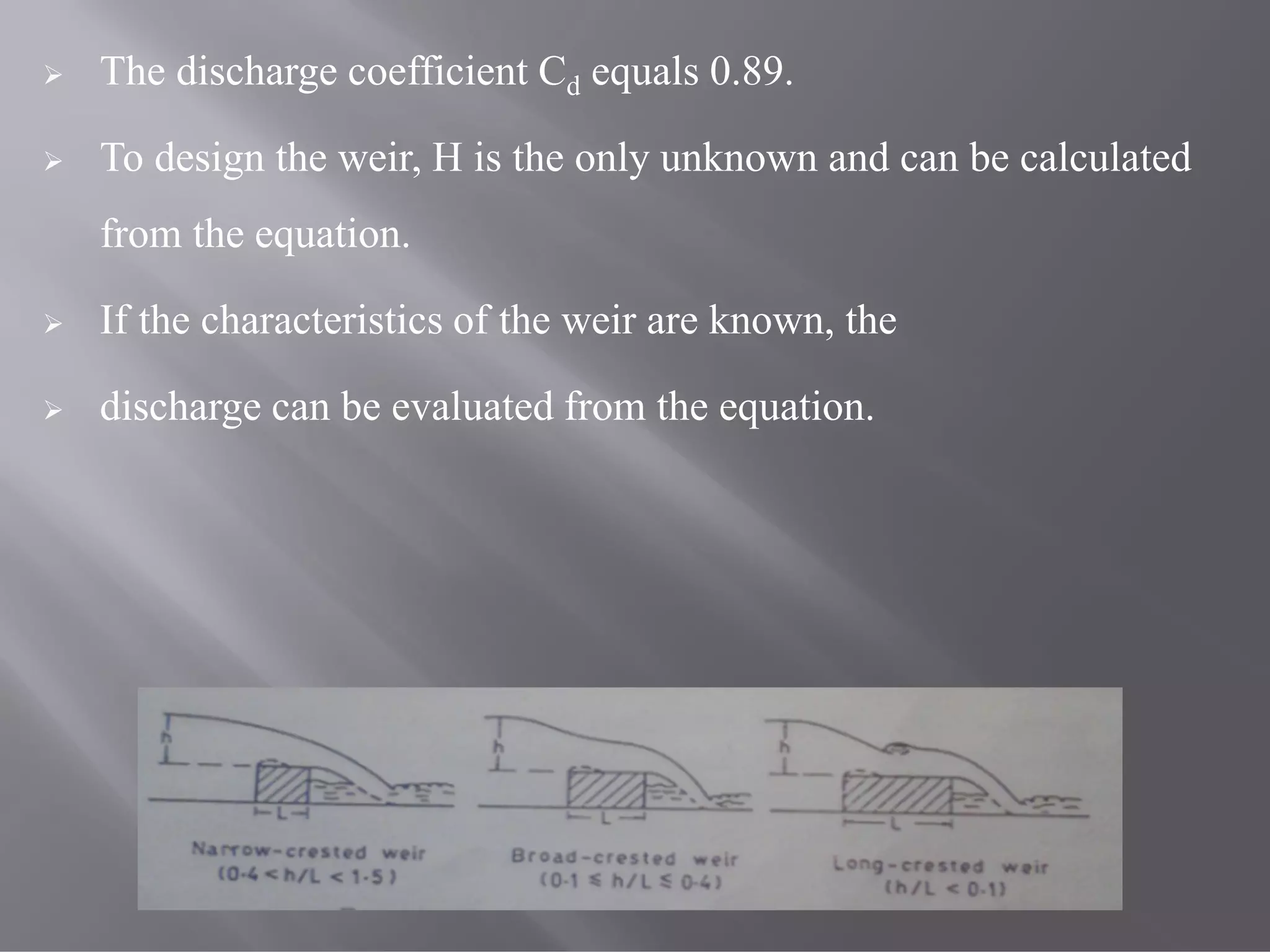
This isthe simplest device for flow measurement.
It is more suitable for large discharges.
The width of the weir is taken as the width of
the waterway.
The following equations is used:
5.1
3
2
3
2
HbgCQ cd
25.
The dischargecoefficient Cd equals 0.89.
To design the weir, H is the only unknown and can be calculated
from the equation.
If the characteristics of the weir are known, the
discharge can be evaluated from the equation.
26.
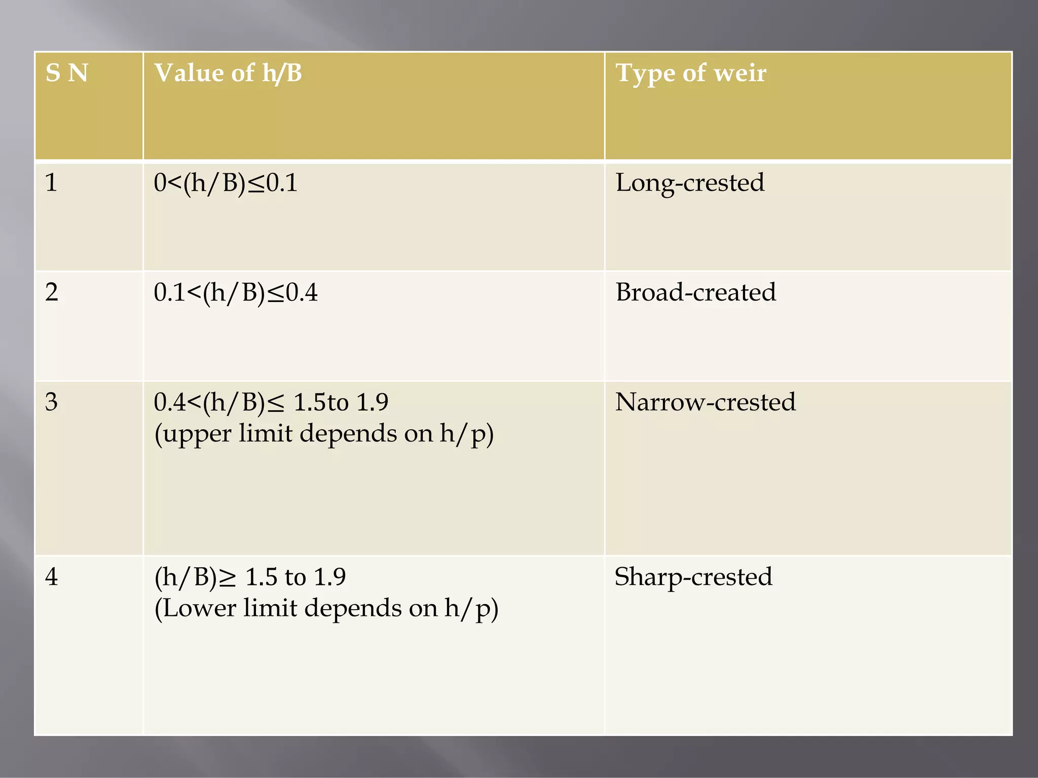
S N Valueof h/B Type of weir
1 0<(h/B)≤0.1 Long-crested
2 0.1<(h/B)≤0.4 Broad-created
3 0.4<(h/B)≤ 1.5to 1.9
(upper limit depends on h/p)
Narrow-crested
4 (h/B)≥ 1.5 to 1.9
(Lower limit depends on h/p)
Sharp-crested
(a) Free fallingweir:
A weir is said to be a free falling weir if downstream liquid level
is below the weir crest.
30.
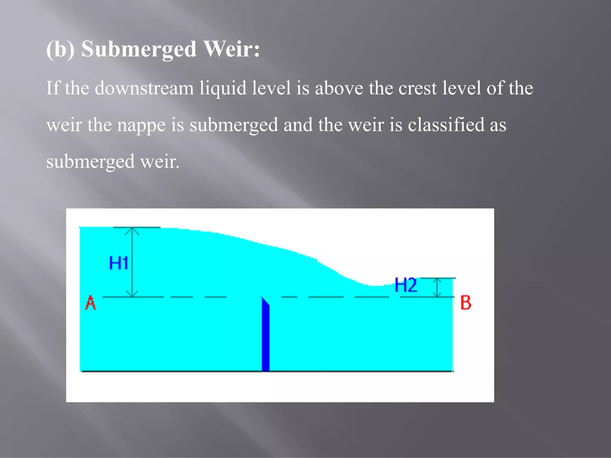
(b) Submerged Weir:
Ifthe downstream liquid level is above the crest level of the
weir the nappe is submerged and the weir is classified as
submerged weir.
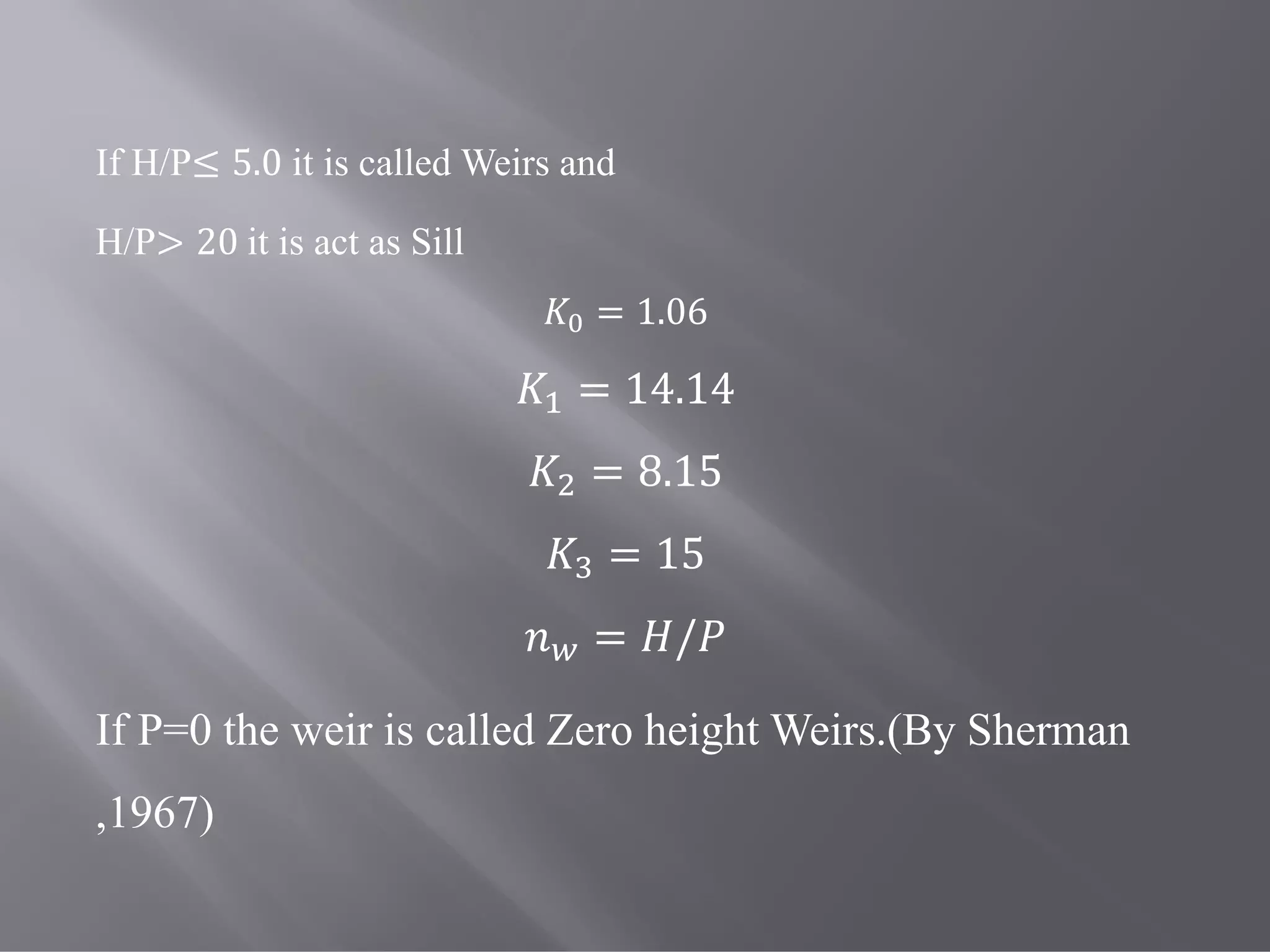
If H/P≤ 5.0it is called Weirs and
H/P> 20 it is act as Sill
= 1.06
= 14.14
= 8.15
= 15
= /
If P=0 the weir is called Zero height Weirs.(By Sherman
,1967)
34.
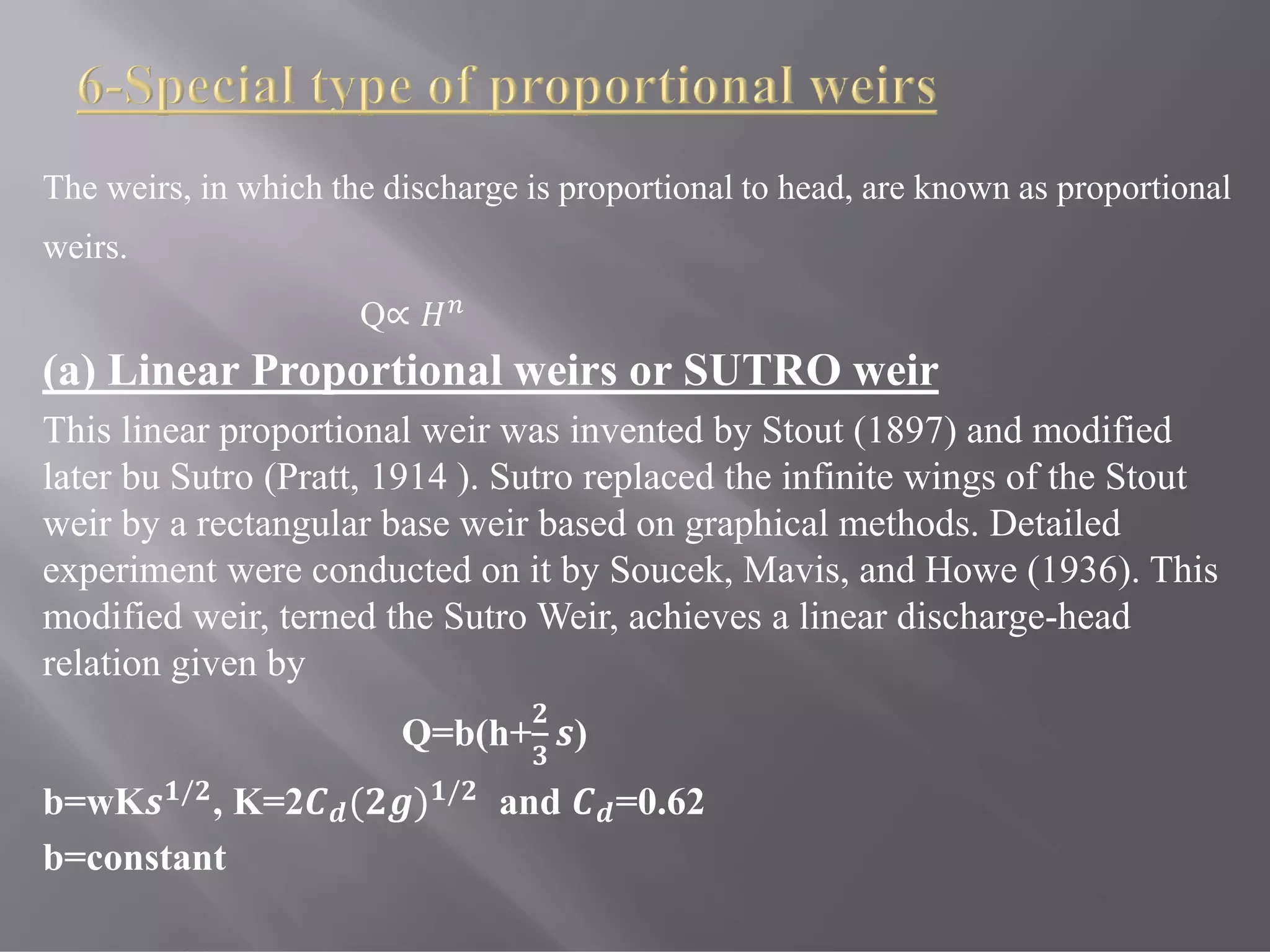
The weirs, inwhich the discharge is proportional to head, are known as proportional
weirs.
Q∝
(a) Linear Proportional weirs or SUTRO weir
This linear proportional weir was invented by Stout (1897) and modified
later bu Sutro (Pratt, 1914 ). Sutro replaced the infinite wings of the Stout
weir by a rectangular base weir based on graphical methods. Detailed
experiment were conducted on it by Soucek, Mavis, and Howe (1936). This
modified weir, terned the Sutro Weir, achieves a linear discharge-head
relation given by
Q=b(h+ )
b=wK / , K=2 ( ) / and =0.62
b=constant
36.
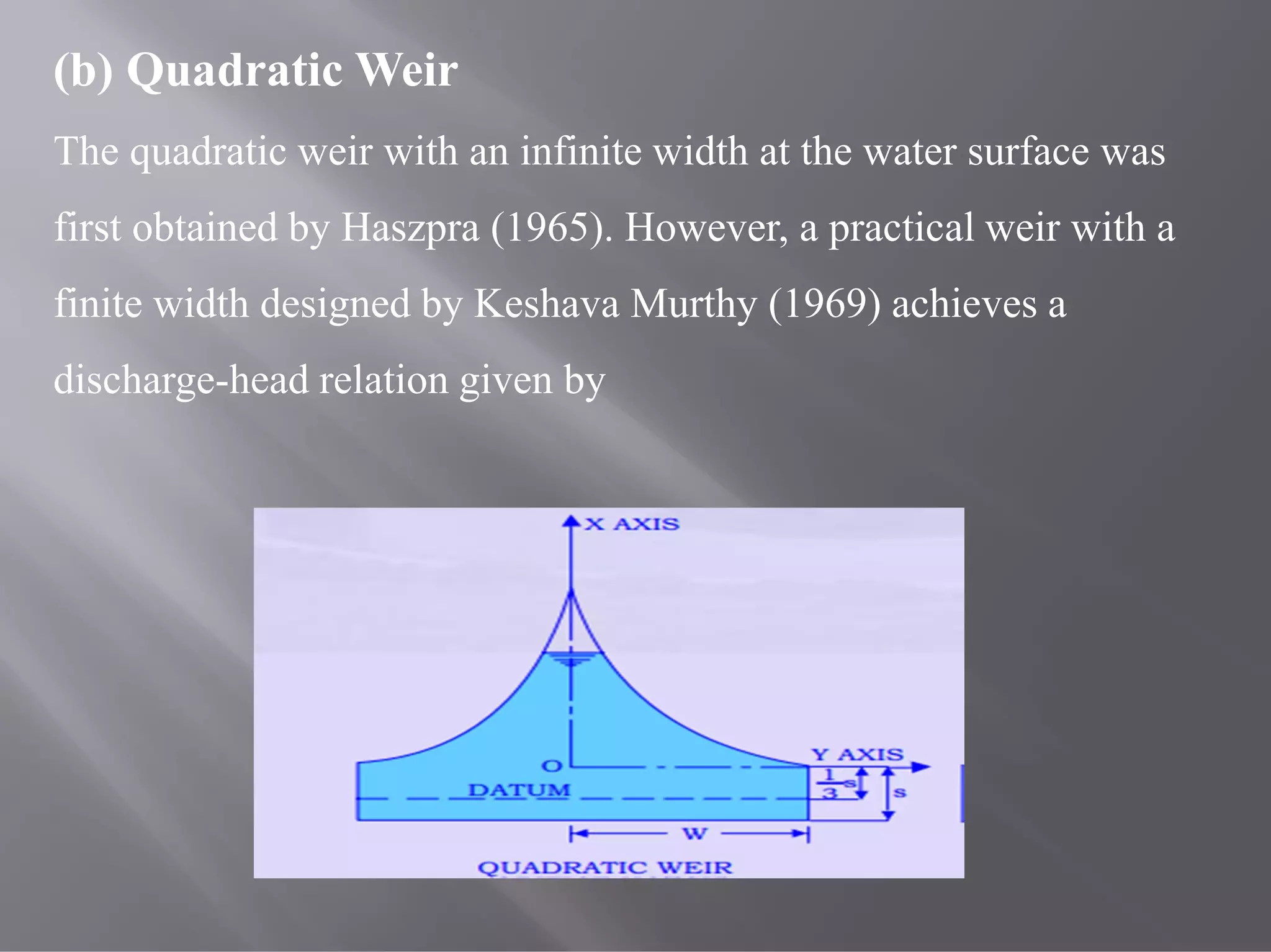
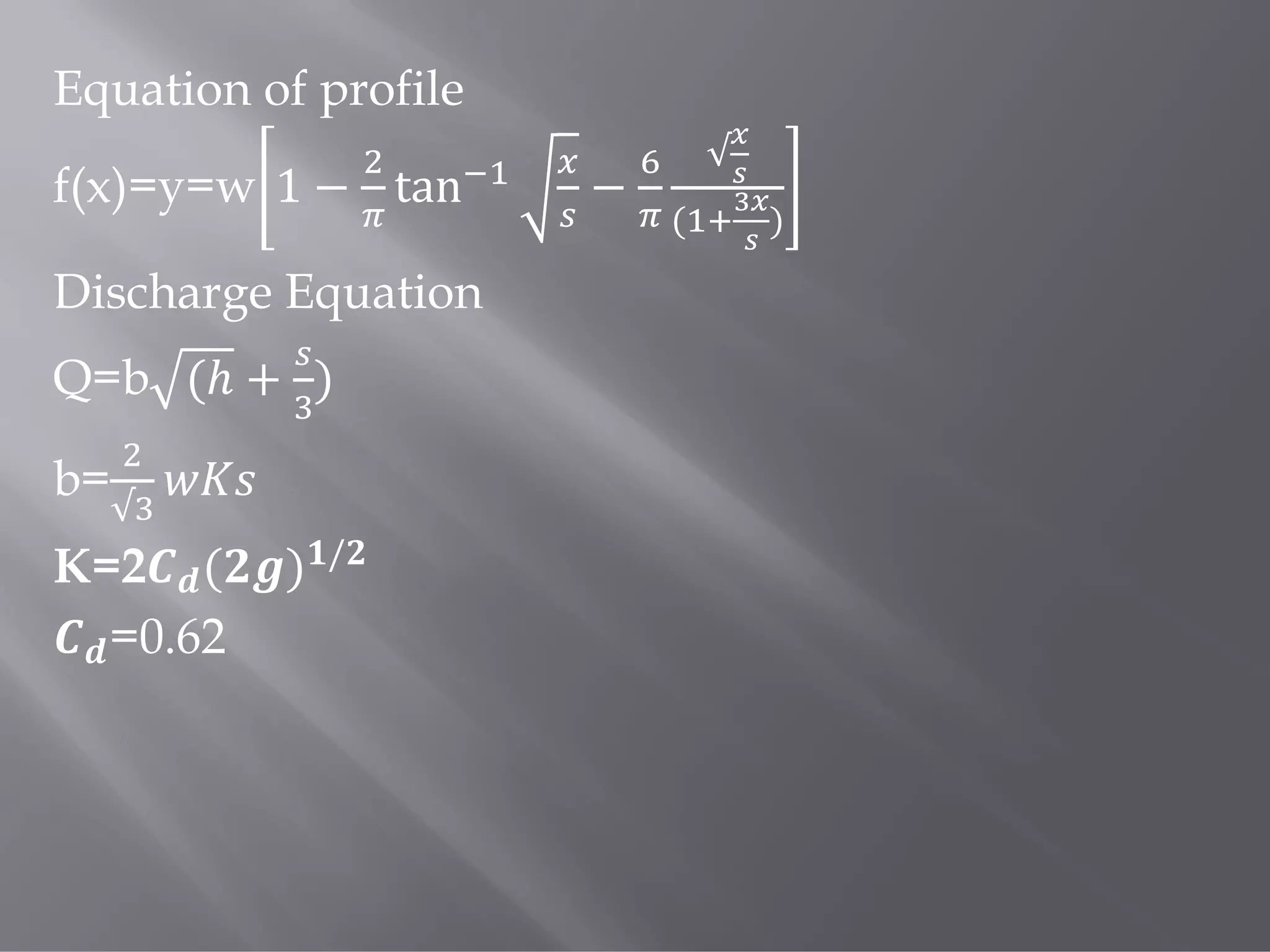
(b) Quadratic Weir
Thequadratic weir with an infinite width at the water surface was
first obtained by Haszpra (1965). However, a practical weir with a
finite width designed by Keshava Murthy (1969) achieves a
discharge-head relation given by
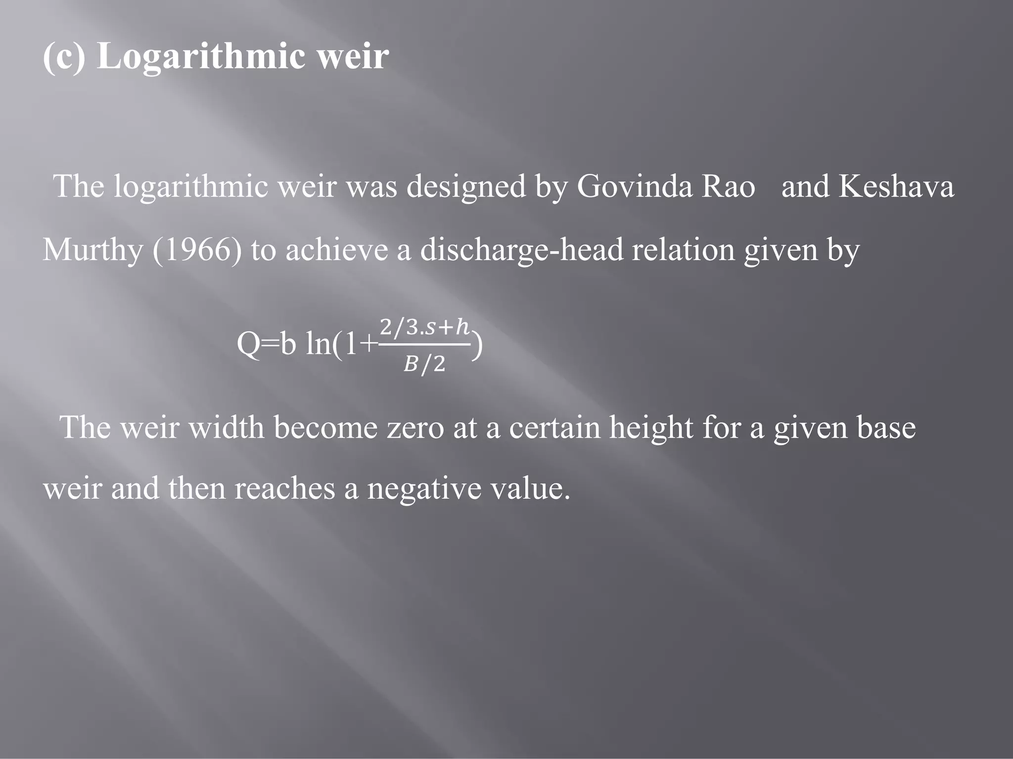
(c) Logarithmic weir
Thelogarithmic weir was designed by Govinda Rao and Keshava
Murthy (1966) to achieve a discharge-head relation given by
Q=b ln(1+
/ .
/
)
The weir width become zero at a certain height for a given base
weir and then reaches a negative value.
39.
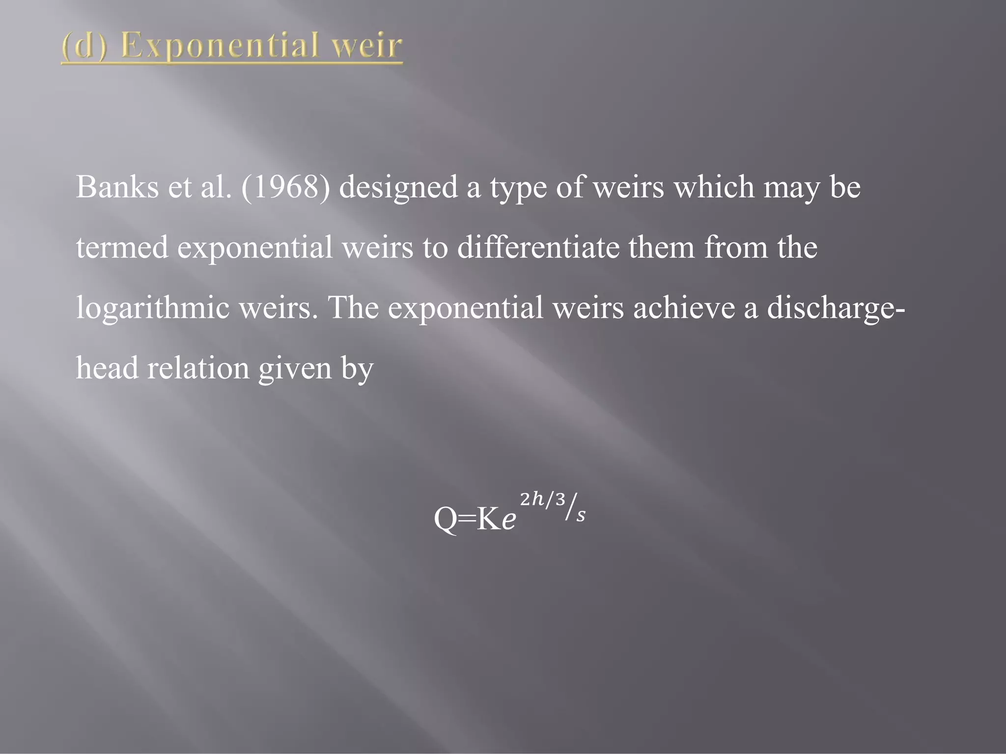
Banks et al.(1968) designed a type of weirs which may be
termed exponential weirs to differentiate them from the
logarithmic weirs. The exponential weirs achieve a discharge-
head relation given by
Q=K
/
40.
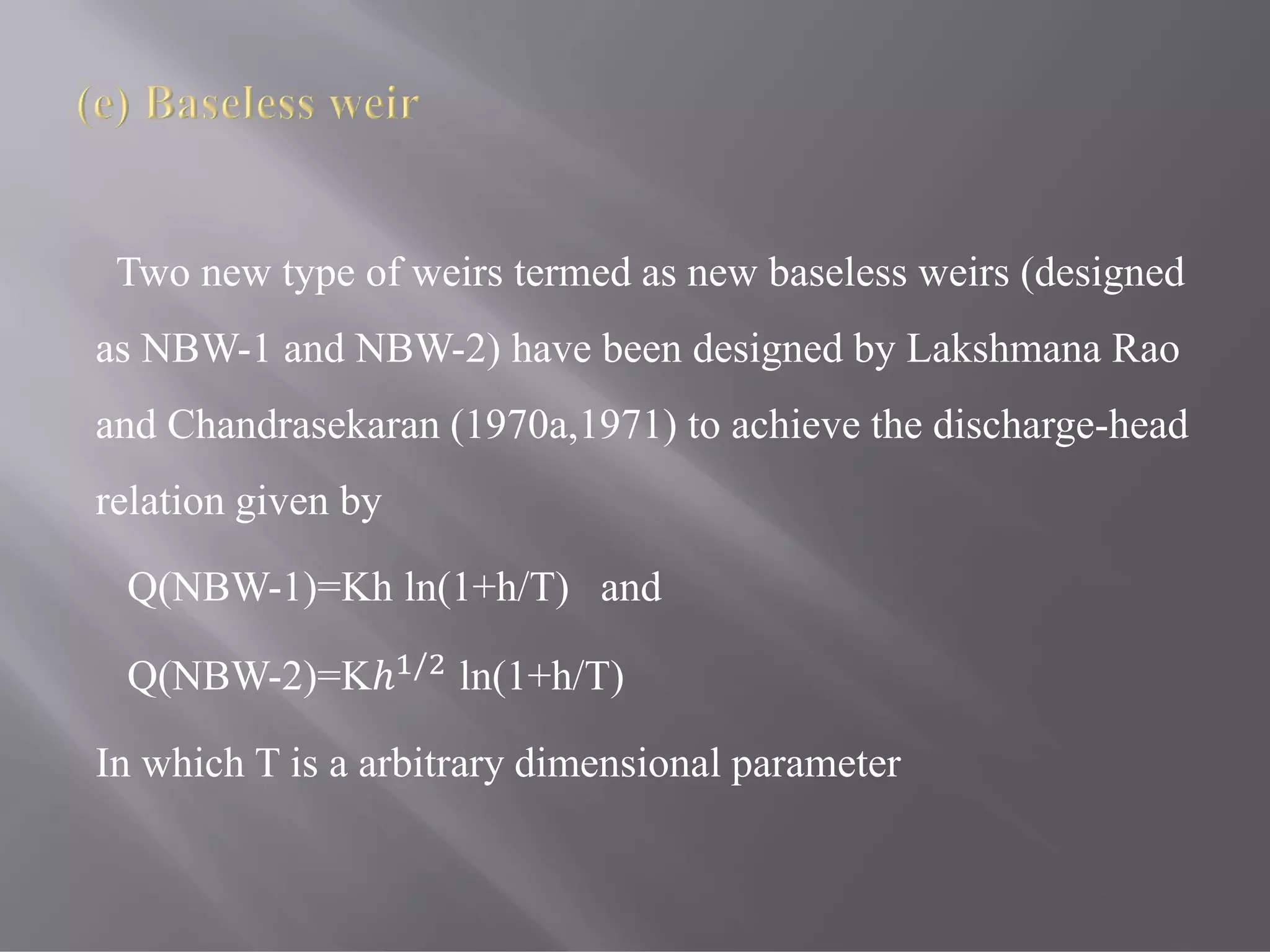
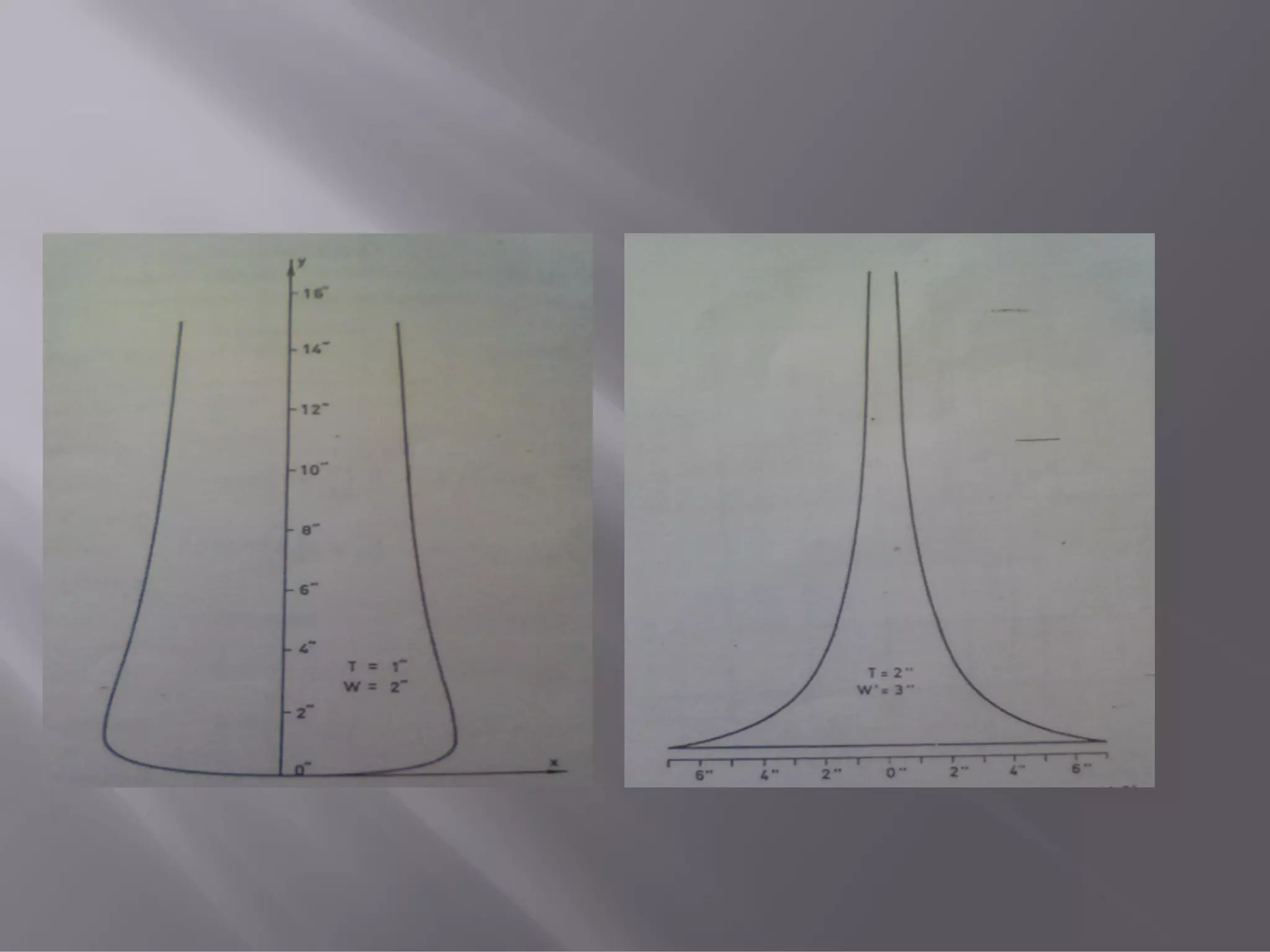
Two new typeof weirs termed as new baseless weirs (designed
as NBW-1 and NBW-2) have been designed by Lakshmana Rao
and Chandrasekaran (1970a,1971) to achieve the discharge-head
relation given by
Q(NBW-1)=Kh ln(1+h/T) and
Q(NBW-2)=Kℎ /
ln(1+h/T)
In which T is a arbitrary dimensional parameter
42.
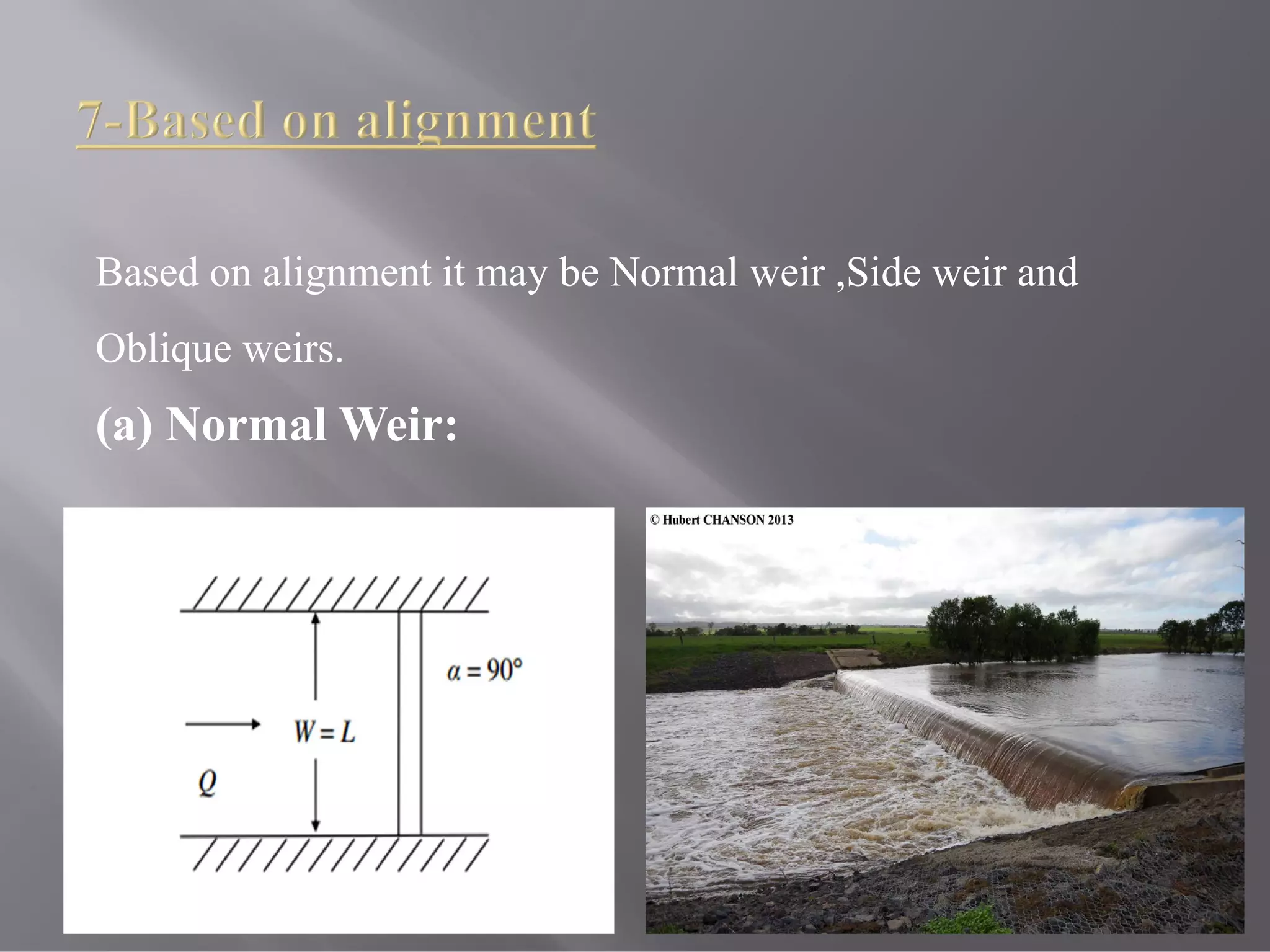
Based on alignmentit may be Normal weir ,Side weir and
Oblique weirs.
(a) Normal Weir:
45.
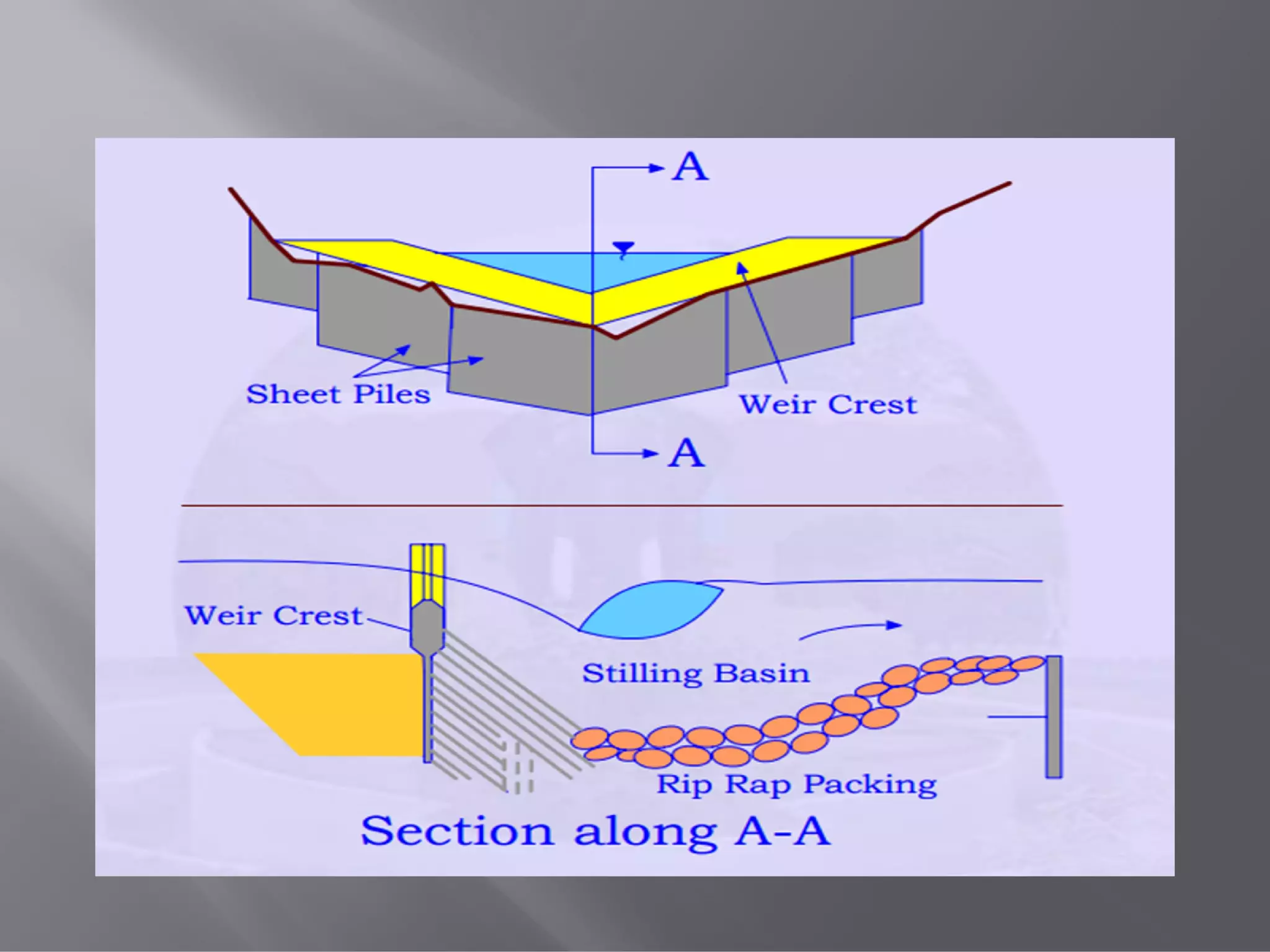
(a) Flat-Vee weir.
Flatvee weir are suitable for measuring accurately a wide range of
flows, relatively easy to install, and are economical. Such weir are
designed by modifying slightly the Crump weir.
46.
To estimate theregime characteristics of a river in relation to
watershed protection and flood prevention measures. A vee Weir
with a very large apex angle and with very little crest width is
installed with weir crest slightly above the channel bed. Figure
shows the details of a Large vee weir.
48.
A labyrinth weiris a linear weir that is folded in plan-view to
increase the crest length for a given channel or spillway width.
Due to the increase in crest length, a labyrinth weir provides an
increase in discharge capacity for a given upstream driving head
relative to traditional linear weir structures. Labyrinth weirs are
particularly well suited for spillway rehabilitation where dam
safety concerns freeboard limitations, and a revised and larger
probable maximum flow have required replacement or
modification of the spillway
50.
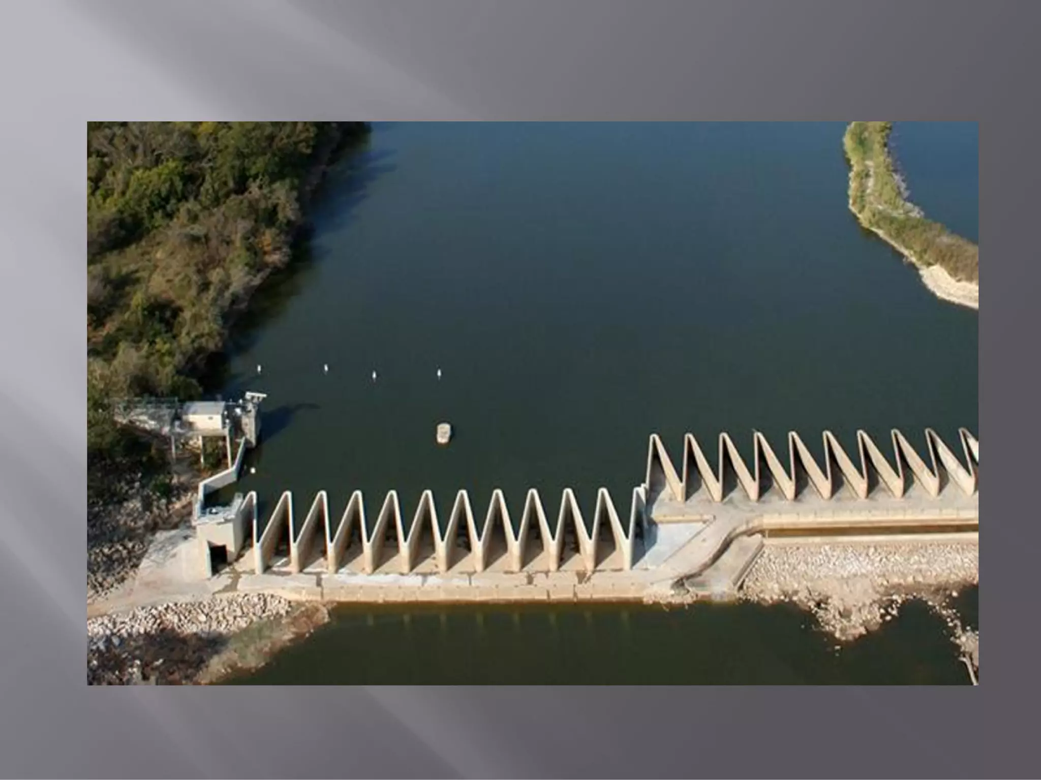
The Piano KeyWeir (PKW) is a particular geometry of weir
associating to a labyrinth shape the use of overhangs to reduce
the basis length. The PKW could thus be directly placed on a
dam crest. Together with its important discharge capacity for
low heads, this geometric feature makes the PKW an interesting
solution for dam rehabilitation. However, its hydraulic design
remains problematic, even at a preliminary stage.

![Suppressed weir
= [ 1 +
4
9
ℎ
ℎ +
− {
4
9
ℎ
ℎ +
} ]
= [ 1 +
4
9
ℎ
ℎ +
( )
− {
4
9
ℎ
ℎ +
( ) } ]
Contracted weir](https://image.slidesharecdn.com/classificationofweisnew-190317160339/75/Classification-of-weis-new-28-2048.jpg)
![Q= 2
Type Given By
Sill > 20
1.06(1 + ) / Kandaswamy
and Rouse
0-∞
[
+
+
+ 1
] .
Swamy
Weir ≤5 0.611+0.08 Rehbock](https://image.slidesharecdn.com/classificationofweisnew-190317160339/75/Classification-of-weis-new-32-2048.jpg)


![09. Silt Theories [Kennedy's Theory].pdf](https://cdn.slidesharecdn.com/ss_thumbnails/09-230714062702-13879994-thumbnail.jpg?width=640&height=640&fit=bounds)