Software Engineering
CSE-221
Presentation Topic:Sequence Diagram
Group: F
Presented by
1. Kamruzzaman Knok
ID: 201311173
2. Md. Sojib Rana
ID: 201311177
3. Md. Mahfuzar Rahaman Tarek
ID: 201311166
Presented to
Umme Rumman
Assistant Professor,
Varendra University
2.
Presentation Outline
Whatis Sequence Diagram?
Purpose of Sequence Diagram
Notation
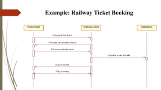
Example
Conclusion
3.
What is SequenceDiagram?
Sequence diagram simply depicts interaction between objects in a
sequential order.
These are also called as “Event Diagram”.
4.
Purpose of SequenceDiagram
1. Model high-level interaction between active objects in a system.
2. Model the interaction between object instances within a collaboration
that realizes a use case.
3. Model the interaction between objects within a collaboration that
realizes an operation.
5.
Notation
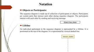
Objects orParticipants:
The sequence diagram is made up of collection of participants or objects. Participants
are system parts that interact each other during sequence diagram. The participants
interact with each other by sending and receiving message.
Lifeline
An individual participant in the sequence diagram is represented by a lifeline. It is
positioned at the top of the diagram. It is represented by vertical dashed line.
6.
Notation
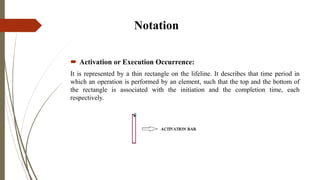
Activation orExecution Occurrence:
It is represented by a thin rectangle on the lifeline. It describes that time period in
which an operation is performed by an element, such that the top and the bottom of
the rectangle is associated with the initiation and the completion time, each
respectively.
7.
Notation
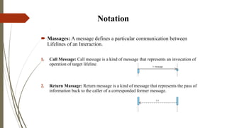
Massages: Amessage defines a particular communication between
Lifelines of an Interaction.
1. Call Message: Call message is a kind of message that represents an invocation of
operation of target lifeline.
2. Return Massage: Return message is a kind of message that represents the pass of
information back to the caller of a corresponded former message.
8.
Notation
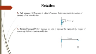
3. Self Message:Self message is a kind of message that represents the invocation of
message of the same lifeline.
4. Destroy Message: Destroy message is a kind of message that represents the request of
destroying the lifecycle of target lifeline.
9.
Notation
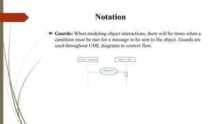
Guards: Whenmodeling object interactions, there will be times when a
condition must be met for a message to be sent to the object. Guards are
used throughout UML diagrams to control flow.
Conclusion
a gooddiagram to use to document a system’s requirements and to
flush out a system’s design.
it shows the interaction logic between the objects in the system in
the time order that the interactions take place.