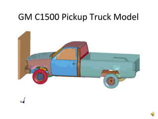
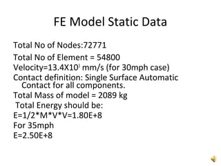
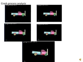
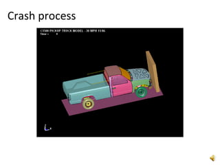
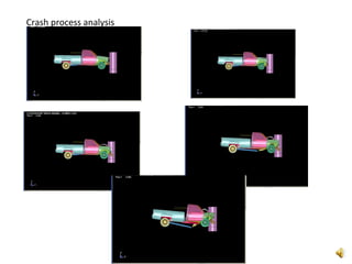
1) Group analyzed crashworthiness of a 1500 pickup truck through FE simulations of frontal impacts at 30 mph and 35 mph and an oblique 30 mph side impact.
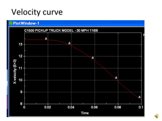
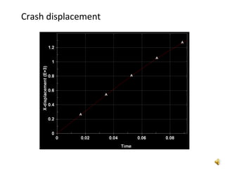
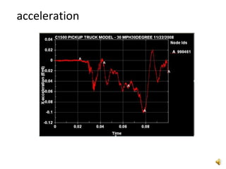
2) Key results included barrier forces, displacements, velocities and accelerations which showed increased impact at higher velocity. Pole impact introduced most stress due to concentration.
3) Analysis provided understanding of FMVSS 208, NCAP tests and how vehicle and components absorb crash energy. Recommendations to improve model and validation were provided.