Download to read offline

![International Research Journal of Engineering and Technology (IRJET) e-ISSN: 2395-0056
Volume: 06 Issue: 04 | Apr 2019 www.irjet.net p-ISSN: 2395-0072
© 2019, IRJET | Impact Factor value: 7.211 | ISO 9001:2008 Certified Journal | Page 419
REFERENCES
[1] Formula Bharat Rulebook 2019
[2] 2017-18 Formula SAE Rules
[3] “Race Car Vehicle Dynamics” William F. Milliken,
Douglas L. Milliken, 1997. Society of Automotive
Engineers.
[4] “Fundamentals of Vehicle Dynamics” SAE Inc.ThomasD
Gillespie.
[5] “Racing and Sports Car Chassis Design” Michael Costin
and David Phipps.
[6] “Design and crash analysis of a rollcage for formula SAE
race car”,IJRET, eISSN: 2319-1163, Volume:03Issue:07
[7] William B. Riley and Albert R. George, “Design, Analysis
and Testing of a Formula SAE Car Chassis”, Cornell
University, 2002-01-3300
[8] Abhijeet Das, “Design of Student Formula Race Car
Chassis”, IJSR, ISSN (Online):2319-7064,Volume4Issue
4, April 2015.](https://image.slidesharecdn.com/irjet-v6i492-190614091305/85/IRJET-Static-Structural-Analysis-of-Formula-Student-Space-Frame-5-320.jpg)

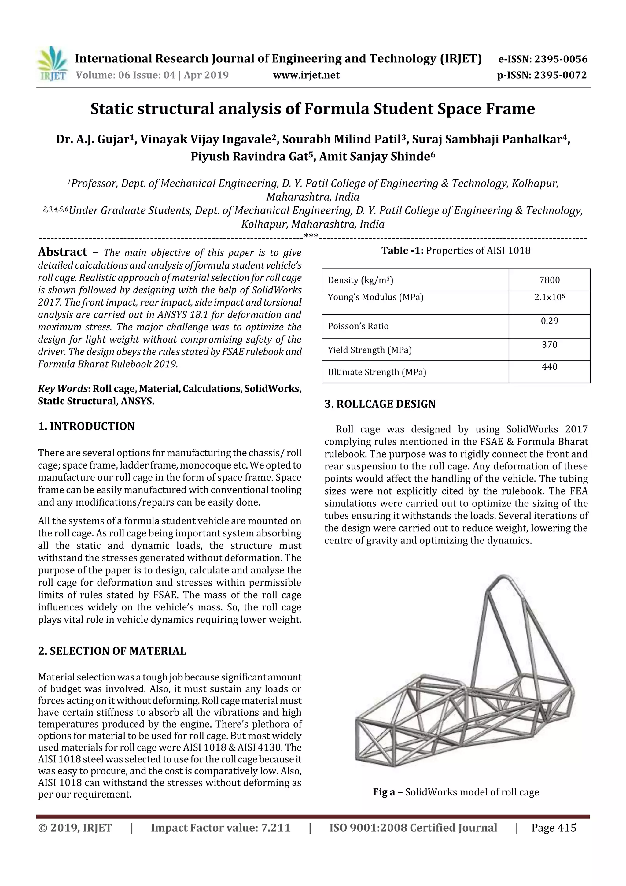
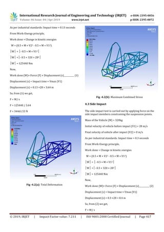
This document presents the static structural analysis of the space frame roll cage for a Formula Student race car. The roll cage was designed in SolidWorks to comply with competition rules. AISI 1018 steel was selected as the material due to its availability, low cost, and ability to withstand stresses. Finite element analysis was performed in ANSYS to simulate front, rear, and side impacts, as well as torsion. Forces for the impact simulations were calculated using the work-energy principle. The analyses showed the roll cage design has sufficient strength with deformations and stresses below permissible limits to safely absorb loads during a crash. The goal of the analysis was to validate the roll cage design and optimize it for strength and low weight.