Downloaded 33 times


![A subroutine call is implemented with the
following microoperations:
CALL:
SP SP-1← : Decrement stack point
M[SP] PC← : Push content of PC onto
the stack
PC←Effective Address : Transfer control
to the subroutine
RETURN:
PC M[SP]← : Pop stack and transfer to
PC
SP SP+1← : Increment stack pointer](https://image.slidesharecdn.com/datatransferandmanipulation-110818112538-phpapp02-170806054216/85/CPU-Organization-Datatransfer-and-manipulation-22-320.jpg)

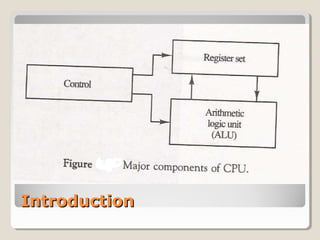
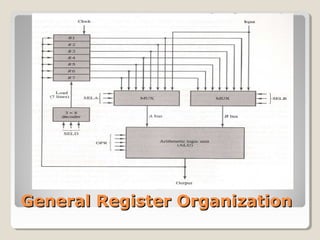
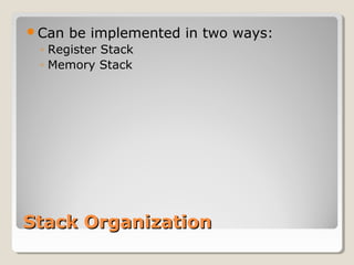
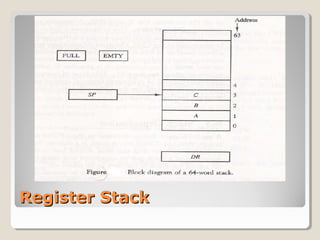
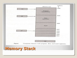
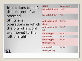
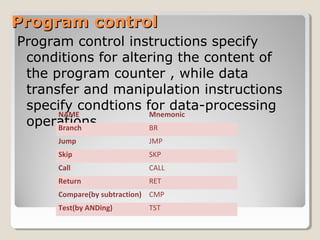
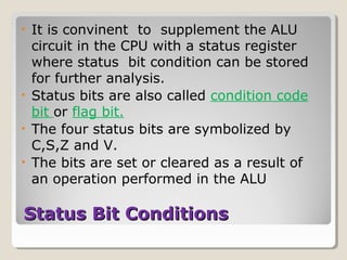
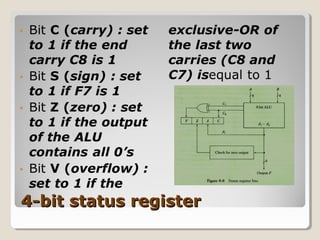
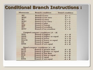
This document discusses CPU organization and how data is transferred and manipulated. It describes different register organizations like general register and stack organizations. It also discusses instruction formats, addressing modes, and different types of instructions for data transfer, manipulation, and program control. Specific instructions like load, store, move, branch, and call are described. The document also covers subroutine calls, returns, program interrupts, and the status register for storing condition codes.