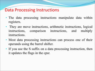
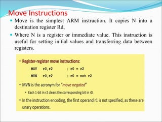
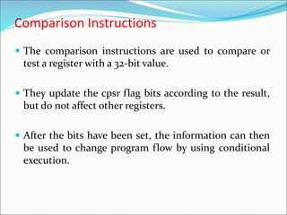
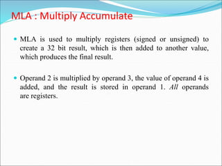
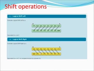
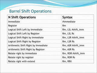
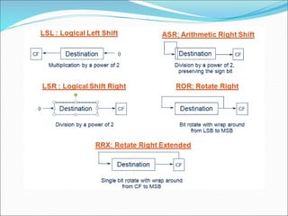
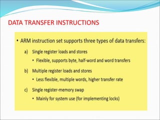
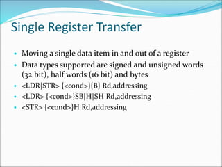
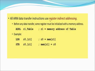
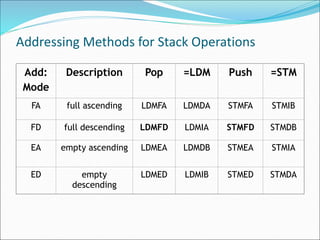
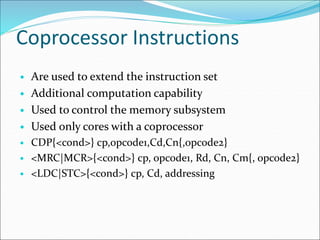
This document provides an overview of the ARM instruction set, which can be categorized into three groups: data processing instructions, data transfer instructions, and control flow instructions. It describes the various data processing instructions like move, arithmetic, logical, comparison, and multiply instructions. It also covers the different addressing modes for load/store single and multiple register instructions. Branch instructions and other instructions for program flow control are also outlined.
![Single Register Transfer
LDR load word into a register Rd <-mem32[address]
STR save byte or word from a register Rd ->mem32[address]
LDRB load byte into a register Rd <-mem8[address]
STRB save byte from a register Rd ->mem8[address]
LDRH load half word into a register Rd <-mem16[address]
STRH save half word from a register Rd ->mem16[address]
LDRSB load signed byte into a register Rd <-SignExtend
(mem8[address])
LDRSH load signed half word into a
register
Rd <-SignExtend
(mem16[address])](https://image.slidesharecdn.com/unit2erts-221213172530-7e4b3cea/85/UNIT-2-ERTS-ppt-24-320.jpg)
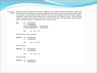
![Index Methods
Index
Method
Data Base
Address
Register
Example
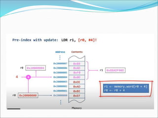
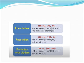
preindex
with
writeback
mem[base+offset] base+
offset
LDR r0, [r1, #4]!
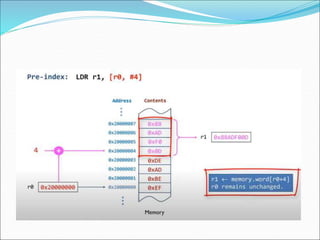
preindex mem[base+offset] not
updated
LDR r0, [r1, #4]
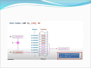
postindex mem[base] base+
offset
LDR r0, [r1], #4](https://image.slidesharecdn.com/unit2erts-221213172530-7e4b3cea/85/UNIT-2-ERTS-ppt-28-320.jpg)
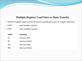
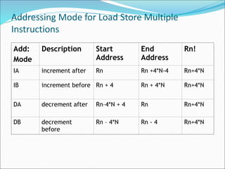
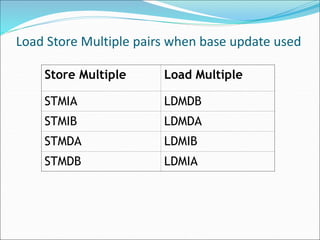
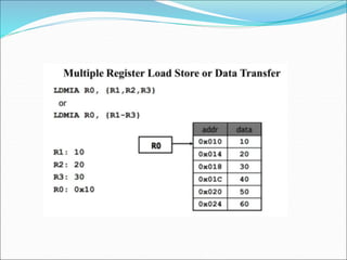
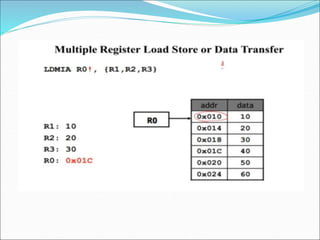
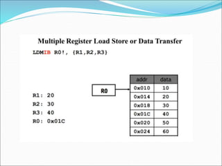
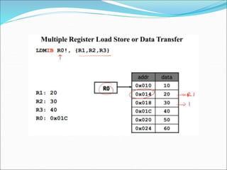
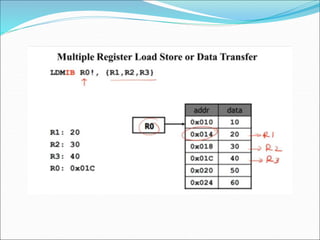
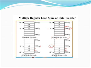
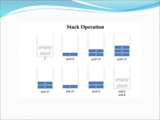
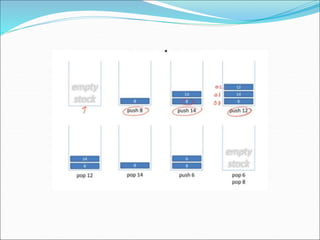
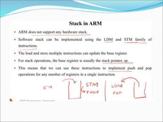
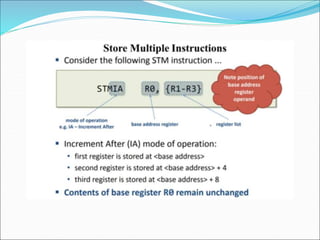
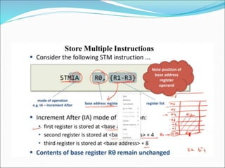
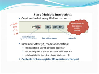
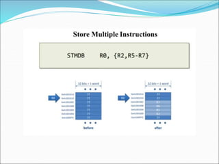
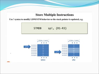
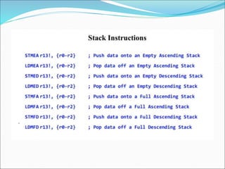
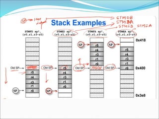
![Multiple Register Transfer
• Load–store multiple instructions can transfer multiple
registers between memory and the processor in a single
instruction.
• Moving blocks of data around memory and saving and
restoring context stacks
• <LDM|STM>{<cond>}<addressing mode> Rn{!},<registers>{^}
LDM load multiple registers {Rd}*N <- mem32[start address +
4*N] optional Rn updated
STM save multiple registers {Rd}*N -> mem32[start address +
4*N] optional Rn updated](https://image.slidesharecdn.com/unit2erts-221213172530-7e4b3cea/85/UNIT-2-ERTS-ppt-36-320.jpg)
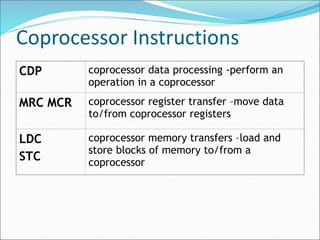
![SWAP Instruction
• Swaps the contents of memory with the contents of a
register
• Atomic operation– it reads and writes a location in the
same bus operation,preventing any other instruction from
reading or writing to that location until it completes.
• SWP{B}{<cond>} Rd, Rm, [Rn]](https://image.slidesharecdn.com/unit2erts-221213172530-7e4b3cea/85/UNIT-2-ERTS-ppt-65-320.jpg)
![SWAP Instruction
SWP swap a word between
memory and a register
tmp=mem32[Rn]
mem32[Rn]=Rm
Rd=tmp
SWPB swap a byte between
memory and a register
tmp=mem8[Rn]
mem8[Rn]=Rm
Rd=tmp](https://image.slidesharecdn.com/unit2erts-221213172530-7e4b3cea/85/UNIT-2-ERTS-ppt-66-320.jpg)
![Program Status Register
Instructions
• 2 instructions to directly control a psr
• MRS - transfers the contents of cpsr or spsr into a
register
• MSR - transfers the contents of register into cpsr or
spsr
N Z C V I F T Mode
31 30 29 28 7 6 5 4 0
Condition Flags Processor Mode
Interrupt
Masks
Thumb State
Function
Bit
Fields
Flags[24:31] Status[16:23] Extension[8:15] Control[0:7]](https://image.slidesharecdn.com/unit2erts-221213172530-7e4b3cea/85/UNIT-2-ERTS-ppt-69-320.jpg)
![Program Status Register
Instructions
• MRS{<cond>} Rd,<cpsr|spsr>
• MSR{<cond>} <cpsr|spsr>_<fields>,Rm
• MSR{<cond>} <cpsr|spsr>_<fields>,#immediate
MRS copy psr to a gpr Rd = psr
MSR move gpr to a psr psr[field] = Rm
MSR move an immediate value to
a psr
psr[field] = immediate](https://image.slidesharecdn.com/unit2erts-221213172530-7e4b3cea/85/UNIT-2-ERTS-ppt-70-320.jpg)
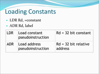
![Loading Constants
Pseudo instruction Actual instruction
LDR r0, =0xff MOV r0, #0xff
LDR r0, =0x55555555 LDR r0, [pc,#offset_12]](https://image.slidesharecdn.com/unit2erts-221213172530-7e4b3cea/85/UNIT-2-ERTS-ppt-75-320.jpg)