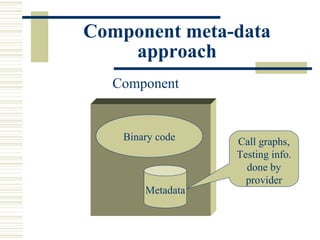
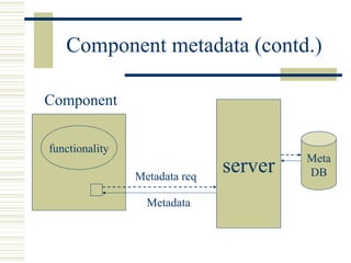
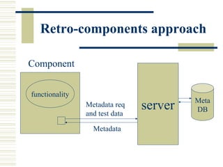
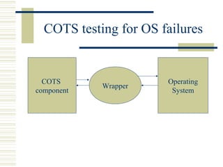
COTS Testing
Diff. With in-house
                components
 Interface (pre and post conditions) are not
  clearly specified.
 No Arch. and code.
 Black boxes to component user.

            Why use COTS
Why COTS Testing


 Failure of Ariane5.
    • explosion resulted
      from insufficiently
      tested software
      reused from the
      Ariane 4 launcher.
COTS Evaluation and selection
Why rigorous evaluation of
               COTS?
 Large number of alternative products.
 Multiple stakeholders.
 Large number of Quality criteria.
 Compatibility with other products.
Why evaluation difficult

 Large number of evaluation criteria.
 Different opinions are usually encountered among
  different stakeholders.
 Evaluation criteria are not easily measurable at
  evaluation time.
 Gathering relevant info. is prohibitively expensive.
 COTS market is changing fast, evaluation must be
  performed several times during lifecycle.
 Evaluation deals with uncertainty info.
AHP Technique

 Originally designed for economic and
  political science domains.
 Requires a pair wise comparison of
  alternatives and pair wise weighting of
  selection criteria.
 Enables consistency analysis of comparisons
  and weights, making possible to assess
  quality of gathered info.
AHP Technique (contd.)

 Allows alternatives to be measured on a ratio
  scale,we can determine how much better an
  alternative compared to other.
 Practically usable if number of alternatives
  and criteria are sufficiently low, because
  comparisons are made by experts.
Selection in practice

Follows three stages
 Informal screening for a set of requirements
  using selection thresholds.
 More systematic evaluation using AHP
  process.
 Detailed Information gathering involves
  testing, prototyping and reading technical
  documents.
State of the art in COTS testing
How to provide information to
                user
 Component meta-data approach.
 Retro-components approach.
 Component test bench approach.
 Built-in test approach.
 Component+ approach.
 STECC strategy.
Component meta-data
    approach
  Component


    Binary code    Call graphs,
                   Testing info.
                     done by
                     provider
        Metadata
Component metadata (contd.)

Component


functionality
                                        Meta
                Metadata req
                               server   DB

                  Metadata
Retro-components approach

Component


functionality
                                         Meta
                Metadata req
                and test data
                                server   DB

                  Metadata
Component test bench
             approach
 A set of test cases called test operation is
  associated with each interface of a
  component.
 A test operation defines the necessary steps
  for testing a specific method.
 The concrete test inputs and expected test
  output packaged in a test operation.
Built-in test approach.

      Component


      Functionality


  Test case     Tester
  generator
Built-in test approach(contd.)

 Normal mode.    Maintenance mode.


                     Functionality

 Functionality

                 Test case     Tester
                 generator
Built-in test approach(contd.)


                     Base Component


            Inheritance


                     Derived
                     Component
Component+ approach
 Tester
              Built-in testing enabled component
Test case
generator
                       Functionality

  Handler
                       Test executor
  Failure
 Recovery
  mech.s        Interface
Disadv. of BIT and
              component+
 Static nature.
 Generally do not ensure that tests are
  conducted as required by the component user
 The component provider makes some
  assumptions concerning the requirements of
  the component user, which again might be
  wrong or inaccurate.
STECC strategy

                     query

  functionality
                    Metadata            Meta
                    Req.       Server   DB
Tester
                    Metadata


                    Test
                  generator
Levels of Testing

 Unit Testing.
 Integration Testing.
 System Testing
Types of testing
 Functionality Testing .
 Reliability Testing.
 Robustness Testing.
 Performance Testing.
 Load Testing.
 Stress Testing.
 Stability Testing.
 Security Testing.
Certifying COTS

When considering a candidate component, developers
need to ask three key questions:
 Does component C fill the developer’s needs?
 Is the quality of component C high enough?
 What impact will component C have on system S?
Certifying COTS(contd.)
CERTIFICATION
            TECHNIQUES
 Black-box component testing.
 System-level fault injection.
 Operational system testing.
 Software Wrapping.
 Interface propagation Analysis.
Black box Testing

 To understand the behavior of a component,
  various inputs are executed and outputs are
  analyzed.
 To catch all types of errors all possible
  combinations of input values should be
  executed.
 To make testing feasible, test cases are
  selected randomly from test case space.
Black box test reduction using
        Input-output Analysis

 Random Testing is not complete.
 To perform complete functional testing,
  number of test cases can be reduced by
  Input-output Analysis.
How to find I/O relationships
 By static analysis or execution analysis of
  program.
Fault Injection


                                   request
                                                Fault
   Fault
                       Component             simulation
simulation
                                                tool
    tool

                                     Exceptions,
      Erroneous
                                     No response
      or malicious
      input
Operational System Testing

 complements system-level fault injection.
 System is operated with random inputs (valid
  and invalid inputs)
 Provides more accurate assessment of COTS
  quality.
 To ensure that a component is a good match
  for the system.
Software Wrapping

        Input wrapper         Output wrapper


Input                   Component              output
Instrumentation configuration
             file
Interface propagation Analysis


  COTS                                    COTS
                  Fault Injector
Component 1                             Component 2


           Modify input, call correct method.
           Call correct method, modify output.
           Call perturbed function.
Fault Injection used for

 Robustness Testing.
 Error propagation Analysis.
 Reliability Testing.
 Security Testing.
Robustness Testing
COTS testing for OS failures


  COTS                 Operating
            Wrapper
component               System
Ballista approach

 Based on fault injection technique.
 Test cases are generated using parameter
  types of an interface.
 Independent of internal functionality.
 Testing is not complete.
Test value Data Base
Test value Data Base(contd.)

 Integer data type: 0, 1, -1, MAXINT, -MAXINT,
  selected powers of two, powers of two minus one,
  and powers of two plus one.
 Float data type: 0, 1, -1, +/-DBL_MIN, +/-
  DBL_MAX, pi, and e.
 Pointer data type: NULL, -1 (cast to a pointer),
  pointer to free’d memory, and pointers to malloc’ed
  buffers of various powers of two in size.
Test value Data Base(contd.)

 String data type (based on the pointer base type):
  includes NULL, -1 (cast to a pointer), pointer to an
  empty string, a string as large as a virtual memory
  page, a string 64K bytes in length.
 File descriptor (based on integer base type): includes
  -1;MAXINT; and various descriptors: to a file open for
  reading, to a file open for writing, to a file whose offset is
  set to end of file, to an empty file, and to a file deleted after
  the file descriptor was assigned.
Test case generation

 All combinations of values for the parameter
  types are generated.
 Number of test cases generated are product
  of number of parameters and test base for
  that type.
Error propagation analysis

 Interface Propagation Analysis is used by injecting
  faults at one component.
 This is done at component integration level.
 A known faulty input is injected using fault injector
  into the system.
 Components effected by this input are observed
  (how they handle the faulty input).
Performance Testing
Middleware

 Application’s execution and Middleware
  cannot be divorced in any meaningful
  way.
 In order to predict the performance of
  application component, performance of
  its middleware should be analyzed.
Performance prediction
          Methodology
Application’s performance prediction is
three step process.
     Obtaining Technology performance.
     Analyzing Architecture specific
      behavioral characteristics.
     Analyzing Application specific
      behavioral characteristics.
Technology performance
        profile
Technology performance
    profile (contd.)
Technology performance
    profile (contd.)
Architecture behavior

Identity Application
Effect of database access thru
              Middleware
            Container

           Session
            bean                      DB
                        Entity
                        bean

 The performance of the entity bean architecture is
  less than 50% of the performance of the session
  bean only Architecture.
Effect of Server Thread

 The performance increases from 2 threads to
  32 threads, stabilizes around 32 to 64
  threads, and gradually decreases as more
  threads are added due to contention.
The Effect of Client Request
                Load.
 Client response time increases with
  concurrent client request rate due to
  contention for server threads.
Effect of Database Contention

 Effect of database contention leads to
  performance that is between 20% and 49%.
Optimal Number of threads
Load Testing
Load Testing

 It is just Performance testing under various
  loads.
 Performance is measured as Connections per
  second (CPS), throughput in bytes per
  second, and round trip time (RTT) .
Load Test Application

       Load test
         App

             Ethernet


     Web         System Under Test
    server
                 App       DB
                server    server
Testing strategy

Load tests will be conducted in three phases.
    1. Consumption of server resources as a function
       of the volume of incoming requests will be
       measured.
    2. Response time for sequential requests will be
       measured.
    3. Response time for concurrent client request
       load will be measured.
Security Testing
Security Risks with COTS

 Component design.
 Component procurement.
 Component integration.
 System maintenance.
Component Design

 Inadvertently flawed component design.
 Intentionally flawed component design.
 Excessive component functionality.
 Open or widely spread component design.
 Insufficient or incorrect documentation.
Component integration

Mismatch between product security levels.
Ex. UNIX and CORBA security integration.

      System maintenance
 Insecure updating.
 Unexpected side effects.
 Maintenance backdoors.
Privacy Data Base Risks
Risks revealed

 Trojan horse in client.
 Information leaking to swap file.
 DBMS log files.
 DBMS ordering of records.
Piracy avoidance techniques

 Hardware and software tokens.
 Dynamic Decryption of Code.
 Watermarking.
 Code Partitioning.
Regression testing for COTS
I-BACCI process

1. Decomposing the binary file of the component;
   and filtering trivial information.
2. Comparison the code sections between the two
   versions.
3. Identification of glue code functions.
4. Identification of change propagation in other
   components/system.
5. Selection of test cases to cover only the affected
   glue code functions (functions in firewall).
Black box understanding of
          COTS
Methods for understanding

 Binary reverse Engg.
 Interface probing.
 Partial automation of interface probing.
Binary reverse Engg.

 Derives the design structure (call graph,
  control graph) from binary code.
 Source code can also be partially extracted
  using decompilation.
 Decompiled source code will have no comments
  and variable names will not be meaningful.
 Licenses forbid decompilation back to source
  code.
Interface probing

 System Developer designs a set of test cases,
  executes, and analyzes outputs.
 Done in an iterative manner.
Disadvantages

 A large number of test cases have to be
  generated and analyzed.
 Some properties may require significant
  probing which may be tedious,labor intensive,
  expensive.
 Developers miss certain limitations and make
  incorrect assumptions.
Partial Automation of interface
               probing
 Based on interface probing.
 Test cases are generated based on scenarios.
 Testing is done in three phases
    1. Scenario description phase.
    2. Search space specification phase.
    3. Test case generation phase.

Cots testing

  • 1.
  • 2.
    Diff. With in-house components  Interface (pre and post conditions) are not clearly specified.  No Arch. and code.  Black boxes to component user. Why use COTS
  • 3.
    Why COTS Testing Failure of Ariane5. • explosion resulted from insufficiently tested software reused from the Ariane 4 launcher.
  • 4.
  • 5.
    Why rigorous evaluationof COTS?  Large number of alternative products.  Multiple stakeholders.  Large number of Quality criteria.  Compatibility with other products.
  • 6.
    Why evaluation difficult Large number of evaluation criteria.  Different opinions are usually encountered among different stakeholders.  Evaluation criteria are not easily measurable at evaluation time.  Gathering relevant info. is prohibitively expensive.  COTS market is changing fast, evaluation must be performed several times during lifecycle.  Evaluation deals with uncertainty info.
  • 7.
    AHP Technique  Originallydesigned for economic and political science domains.  Requires a pair wise comparison of alternatives and pair wise weighting of selection criteria.  Enables consistency analysis of comparisons and weights, making possible to assess quality of gathered info.
  • 8.
    AHP Technique (contd.) Allows alternatives to be measured on a ratio scale,we can determine how much better an alternative compared to other.  Practically usable if number of alternatives and criteria are sufficiently low, because comparisons are made by experts.
  • 9.
    Selection in practice Followsthree stages  Informal screening for a set of requirements using selection thresholds.  More systematic evaluation using AHP process.  Detailed Information gathering involves testing, prototyping and reading technical documents.
  • 10.
    State of theart in COTS testing
  • 11.
    How to provideinformation to user  Component meta-data approach.  Retro-components approach.  Component test bench approach.  Built-in test approach.  Component+ approach.  STECC strategy.
  • 12.
    Component meta-data approach Component Binary code Call graphs, Testing info. done by provider Metadata
  • 13.
    Component metadata (contd.) Component functionality Meta Metadata req server DB Metadata
  • 14.
    Retro-components approach Component functionality Meta Metadata req and test data server DB Metadata
  • 15.
    Component test bench approach  A set of test cases called test operation is associated with each interface of a component.  A test operation defines the necessary steps for testing a specific method.  The concrete test inputs and expected test output packaged in a test operation.
  • 16.
    Built-in test approach. Component Functionality Test case Tester generator
  • 17.
    Built-in test approach(contd.) Normal mode. Maintenance mode. Functionality Functionality Test case Tester generator
  • 18.
    Built-in test approach(contd.) Base Component Inheritance Derived Component
  • 19.
    Component+ approach Tester Built-in testing enabled component Test case generator Functionality Handler Test executor Failure Recovery mech.s Interface
  • 20.
    Disadv. of BITand component+  Static nature.  Generally do not ensure that tests are conducted as required by the component user  The component provider makes some assumptions concerning the requirements of the component user, which again might be wrong or inaccurate.
  • 21.
    STECC strategy query functionality Metadata Meta Req. Server DB Tester Metadata Test generator
  • 22.
    Levels of Testing Unit Testing.  Integration Testing.  System Testing
  • 23.
    Types of testing Functionality Testing .  Reliability Testing.  Robustness Testing.  Performance Testing.  Load Testing.  Stress Testing.  Stability Testing.  Security Testing.
  • 24.
    Certifying COTS When consideringa candidate component, developers need to ask three key questions:  Does component C fill the developer’s needs?  Is the quality of component C high enough?  What impact will component C have on system S?
  • 25.
  • 26.
    CERTIFICATION TECHNIQUES  Black-box component testing.  System-level fault injection.  Operational system testing.  Software Wrapping.  Interface propagation Analysis.
  • 27.
    Black box Testing To understand the behavior of a component, various inputs are executed and outputs are analyzed.  To catch all types of errors all possible combinations of input values should be executed.  To make testing feasible, test cases are selected randomly from test case space.
  • 28.
    Black box testreduction using Input-output Analysis  Random Testing is not complete.  To perform complete functional testing, number of test cases can be reduced by Input-output Analysis.
  • 31.
    How to findI/O relationships  By static analysis or execution analysis of program.
  • 32.
    Fault Injection request Fault Fault Component simulation simulation tool tool Exceptions, Erroneous No response or malicious input
  • 33.
    Operational System Testing complements system-level fault injection.  System is operated with random inputs (valid and invalid inputs)  Provides more accurate assessment of COTS quality.  To ensure that a component is a good match for the system.
  • 34.
    Software Wrapping Input wrapper Output wrapper Input Component output
  • 36.
  • 37.
    Interface propagation Analysis COTS COTS Fault Injector Component 1 Component 2  Modify input, call correct method.  Call correct method, modify output.  Call perturbed function.
  • 38.
    Fault Injection usedfor  Robustness Testing.  Error propagation Analysis.  Reliability Testing.  Security Testing.
  • 39.
  • 40.
    COTS testing forOS failures COTS Operating Wrapper component System
  • 41.
    Ballista approach  Basedon fault injection technique.  Test cases are generated using parameter types of an interface.  Independent of internal functionality.  Testing is not complete.
  • 42.
  • 43.
    Test value DataBase(contd.)  Integer data type: 0, 1, -1, MAXINT, -MAXINT, selected powers of two, powers of two minus one, and powers of two plus one.  Float data type: 0, 1, -1, +/-DBL_MIN, +/- DBL_MAX, pi, and e.  Pointer data type: NULL, -1 (cast to a pointer), pointer to free’d memory, and pointers to malloc’ed buffers of various powers of two in size.
  • 44.
    Test value DataBase(contd.)  String data type (based on the pointer base type): includes NULL, -1 (cast to a pointer), pointer to an empty string, a string as large as a virtual memory page, a string 64K bytes in length.  File descriptor (based on integer base type): includes -1;MAXINT; and various descriptors: to a file open for reading, to a file open for writing, to a file whose offset is set to end of file, to an empty file, and to a file deleted after the file descriptor was assigned.
  • 45.
    Test case generation All combinations of values for the parameter types are generated.  Number of test cases generated are product of number of parameters and test base for that type.
  • 46.
    Error propagation analysis Interface Propagation Analysis is used by injecting faults at one component.  This is done at component integration level.  A known faulty input is injected using fault injector into the system.  Components effected by this input are observed (how they handle the faulty input).
  • 47.
  • 48.
    Middleware  Application’s executionand Middleware cannot be divorced in any meaningful way.  In order to predict the performance of application component, performance of its middleware should be analyzed.
  • 49.
    Performance prediction Methodology Application’s performance prediction is three step process.  Obtaining Technology performance.  Analyzing Architecture specific behavioral characteristics.  Analyzing Application specific behavioral characteristics.
  • 50.
  • 51.
    Technology performance profile (contd.)
  • 52.
    Technology performance profile (contd.)
  • 53.
  • 54.
    Effect of databaseaccess thru Middleware Container Session bean DB Entity bean  The performance of the entity bean architecture is less than 50% of the performance of the session bean only Architecture.
  • 55.
    Effect of ServerThread  The performance increases from 2 threads to 32 threads, stabilizes around 32 to 64 threads, and gradually decreases as more threads are added due to contention.
  • 56.
    The Effect ofClient Request Load.  Client response time increases with concurrent client request rate due to contention for server threads.
  • 57.
    Effect of DatabaseContention  Effect of database contention leads to performance that is between 20% and 49%.
  • 58.
  • 59.
  • 60.
    Load Testing  Itis just Performance testing under various loads.  Performance is measured as Connections per second (CPS), throughput in bytes per second, and round trip time (RTT) .
  • 61.
    Load Test Application Load test App Ethernet Web System Under Test server App DB server server
  • 62.
    Testing strategy Load testswill be conducted in three phases. 1. Consumption of server resources as a function of the volume of incoming requests will be measured. 2. Response time for sequential requests will be measured. 3. Response time for concurrent client request load will be measured.
  • 63.
  • 64.
    Security Risks withCOTS  Component design.  Component procurement.  Component integration.  System maintenance.
  • 65.
    Component Design  Inadvertentlyflawed component design.  Intentionally flawed component design.  Excessive component functionality.  Open or widely spread component design.  Insufficient or incorrect documentation.
  • 66.
    Component integration Mismatch betweenproduct security levels. Ex. UNIX and CORBA security integration. System maintenance  Insecure updating.  Unexpected side effects.  Maintenance backdoors.
  • 67.
  • 68.
    Risks revealed  Trojanhorse in client.  Information leaking to swap file.  DBMS log files.  DBMS ordering of records.
  • 69.
    Piracy avoidance techniques Hardware and software tokens.  Dynamic Decryption of Code.  Watermarking.  Code Partitioning.
  • 70.
  • 71.
    I-BACCI process 1. Decomposingthe binary file of the component; and filtering trivial information. 2. Comparison the code sections between the two versions. 3. Identification of glue code functions. 4. Identification of change propagation in other components/system. 5. Selection of test cases to cover only the affected glue code functions (functions in firewall).
  • 72.
  • 73.
    Methods for understanding Binary reverse Engg.  Interface probing.  Partial automation of interface probing.
  • 74.
    Binary reverse Engg. Derives the design structure (call graph, control graph) from binary code.  Source code can also be partially extracted using decompilation.  Decompiled source code will have no comments and variable names will not be meaningful.  Licenses forbid decompilation back to source code.
  • 75.
    Interface probing  SystemDeveloper designs a set of test cases, executes, and analyzes outputs.  Done in an iterative manner.
  • 76.
    Disadvantages  A largenumber of test cases have to be generated and analyzed.  Some properties may require significant probing which may be tedious,labor intensive, expensive.  Developers miss certain limitations and make incorrect assumptions.
  • 77.
    Partial Automation ofinterface probing  Based on interface probing.  Test cases are generated based on scenarios.  Testing is done in three phases 1. Scenario description phase. 2. Search space specification phase. 3. Test case generation phase.