The document discusses thermal-driven refrigeration systems as an alternative to conventional air conditioning that uses less electricity and pollutes less. It summarizes two common absorption refrigeration pairs: ammonia-water and water-lithium bromide. It then introduces a new sorbent-sorptive pair using sodium thiocyanate as the absorbent and ammonia as the refrigerant. The document includes schematics of typical absorption cycles and the components involved, such as the evaporator, absorber, generator, condenser and expansion valves. It provides a detailed description of the refrigeration cycle using the new sodium thiocyanate-ammonia pair.

![LIST OF FIGURES
FIGURE 1. Schematic of the ammonia absorption system [5]...................................................... 5
FIGURE 2. Schematic of a solar driven Water-LiBr absorption refrigeration system [4]............ 7
FIGURE 3. The schematic of the absorption refrigeration cycle [1]............................................. 8](https://image.slidesharecdn.com/221f10d1-2a53-430d-a0d6-6bda2acaca6d-160113212407/85/Cooling-and-Moisture-Control-System-3-320.jpg)
![1.0 INTRODUCTION
The recent focus in both research and development are thermally driven refrigeration
systems as they do not deplete the ozone layer and require less use of electricity [1]. “Conventional
air-conditioning systems require high quality energy, electricity, generated from primary energy
sources” as well as contribute to increasing pollution levels [2]. Therefore, another alternative
system being used for cooling residential and light commercial and industrial process application
is an absorption cooling system [1]. This report will outline a few details, including the cycle model
description and the engineering drawings, of the thermal-driven refrigeration system that involves
a new sorbent-sorptive as the working pair.
2.0 ADVANCED ABSORPTION SYSTEM
A simple absorption cycle is when two fluids and a heat input is used to create a
refrigeration effect rather than using electricity, as that is the usual method for vapor compression
cycles [2]. The purpose of an absorption refrigeration cycle is to remove heat through the process
of evaporating a refrigerant at a low pressure and “the rejection of heat through the condensation
of the refrigerant at a higher pressure” [2]. In the system, the absorption of a refrigerant involves
a transport medium, or called the absorbent, and the most common refrigerant used is ammonia
(NH3), while water (H2O) serves the role of the absorbent, especially for applications below 32⁰ F
[2]. However, this report focuses on a new pair where the active component of the absorbent is
sodium thiocyanate (NaSCN) and the refrigerant remains to be ammonia [1].
1.1 AIR-COOLED NH3-H2O
An air cooled NH3-H2O absorption refrigeration system, as mentioned before is the
most common sorbent-sorptive pair which can be used for small scale applications like](https://image.slidesharecdn.com/221f10d1-2a53-430d-a0d6-6bda2acaca6d-160113212407/85/Cooling-and-Moisture-Control-System-4-320.jpg)
![residential cooling which is driven by solar heated hot water [3]. There are several systems
that use this pair and some suggests that this system could possibly “reduce fabrication and
maintenance costs of both the solar collection system and the absorption chiller” [3].
The NH3-H2O is a very common pair as it is a very stable solution that can be used
with many materials, except for copper and its alloys because ammonia causes them to
corrode [4]. A typical ammonia-water absorption system has the following components:
evaporator, absorber, pump, generator, rectifier, condenser and expansion valve. In the
evaporator is where the ammonia which is in liquid state produces the cooling effect,
absorbing the heat from the water and evaporating it [4]. The ammonia, in vapor state,
moves to the absorber where the weak ammonia-water solution is [4]. The water in that
solution is unsaturated and is able to absorb higher quantities of ammonia gas which it does
when the ammonia vapor comes in from the evaporator, thus making it a strong solution
[4]. This strong solution of ammonia and water is then pumped at a high pressure through
the pump to the generator [4]. In the generator the strong solution is heated by an external
source which vaporizes the refrigerant ammonia and the rectifier is a heat exchanger that
is cooled by the water and is used to cool the condenser [4]. The high pressure ammonia
vapor enters the condenser in which it is cooled by air or water, converting it back to a
liquid state [4]. It then passes through the expansion valve where the temperature and the
pressure immediately decreases [4]. The ammonia then re-enters into the evaporator,
ultimately creating the cooling effect.](https://image.slidesharecdn.com/221f10d1-2a53-430d-a0d6-6bda2acaca6d-160113212407/85/Cooling-and-Moisture-Control-System-5-320.jpg)
![A specific example of an ammonia-water absorption cycle is illustrated with a
schematic in Fig 1. The main components in the system includes a generator, an absorber,
a rectifier, a solution pump, a condenser, an evaporator and a sub-cooling economizer [5].
The generator is the direct-gas fixed boiler that is being supplied with heat from a direct-
fired burner, the absorber includes two sections: the solution-cooled absorber in which the
pre-absorption occurs and the final absorber which is cooled by the atmospheric air [5].
The rectifier that is “being cooled by a strong solution refluxes the ammonia-condensate
back to the generator concentrating it in the vapor coming from the generator” [5]. A
solution pump is a pulse pump that has a reciprocating motion that discharges strong
solution with a use of a sealing diaphragm [5]. The condenser is a finned tube air cooled
exchanger while the evaporator is a shell and tube heat exchangers [5]. Finally, the sub-
cooling economizer is just a tube in tube heat exchanger [5].
FIGURE 1. Schematic of the ammonia absorption system [5].](https://image.slidesharecdn.com/221f10d1-2a53-430d-a0d6-6bda2acaca6d-160113212407/85/Cooling-and-Moisture-Control-System-6-320.jpg)
![However, some of the disadvantages to an ammonia-water pair absorption cooling
system is that “ammonia is toxic and its usage is limited in some countries to the large
capacity systems or secondary heat exchangers to isolate the ammonia” [4]. Since the
system has a “high water content in the vapor phase [it] requires an auxiliary rectifier to
separate it from [ammonia]” [1].
1.2 H2O-LiBr
Another common absorption system is with the use water-lithium bromide pair. It
was first tested in the 1940’s where the water acted as the refrigerant while the lithium
bromide was used as the absorbent [4]. The typical components in this system includes an
evaporator, absorber and a generator. At low pressure and temperature, water enters into
the evaporator and due to its low pressure, the water is in mixture phases of both a liquid
and vapor [4]. The “water refrigerant absorbs the heat from the substance to be chilled and
gets fully evaporated. It then enters the absorber” [4]. The lithium bromide solution resides
in the absorber and thus the water-lithium bromide solution is formed which is then
pumped to the generator by a pump [4]. In the generator, heat is supplied to the solution
resulting in the water vaporizing and passing to the condenser where it is cooled [4]. As
the water moves along the system, it loses its pressure and temperature and when it re-
enters the evaporator, it produces the cooling effect [4]. The lithium bromide, meanwhile,
exits the generator and reenters the absorber. An example of such a system that is solar
driven is illustrated below with a schematic in Fig. 2.](https://image.slidesharecdn.com/221f10d1-2a53-430d-a0d6-6bda2acaca6d-160113212407/85/Cooling-and-Moisture-Control-System-7-320.jpg)
![The use of water-lithium bromide is an effective absorption system as it has an
higher coefficient of performance than the ammonia water system, as “water is an excellent
refrigerant due to its high latent heat” [4]. However, some of the disadvantages to this
system is that the applications are restricted where the cooling requirements are above the
freezing point of 0⁰ C [4]. In addition, “the disadvantage of the H2O-LiBr system came
from its negative pressure and corrosion” [1].
3.0 NEW SORBENT-SORPTIVE PAIR
The new sorbent-sorptive pair is a salt mixture, first developed by the DY Refrigeration
Inc. and is being used in the ice-maker fishery industry [1]. The active component of the absorbent
is the sodium thiocyanate while ammonia is the refrigerant used.
FIGURE 2. Schematic of a solar driven Water-LiBr absorption refrigeration system [4].](https://image.slidesharecdn.com/221f10d1-2a53-430d-a0d6-6bda2acaca6d-160113212407/85/Cooling-and-Moisture-Control-System-8-320.jpg)
![3.1 CYCLE MODEL DESCRIPTION
Similar to that of the absorption system mentioned above, Fig. 3 also illustrates the
main components such as the evaporator, condenser, generator and absorber. The high
pressure liquid ammonia, passing through the expansion valve, V1, to the evaporator
reduces in pressure [1]. In the evaporator, the liquid ammonia vaporizes by the absorption
of heat from the material being cooled, which results in a low partial pressure vapor [1].
This vapor then moves to the absorber in which the strong solution of sodium thiocyanate
resides after coming in through the generator absorber exchanger [1]. This mixture creates
the weak solution that is pumped by the circulation pump to the solution heat exchanger.
From there it moves towards the generator where the solution is brought to a boil [1]. “The
remaining solution flows back to the absorber and the superheated vapor ammonia passes
into the condenser and liquefied to high pressure liquid ammonia by releasing heat to the
cooling material, and thus, completes the cycle” [1].
FIGURE 3. The schematic of the absorption refrigeration cycle [1].](https://image.slidesharecdn.com/221f10d1-2a53-430d-a0d6-6bda2acaca6d-160113212407/85/Cooling-and-Moisture-Control-System-9-320.jpg)
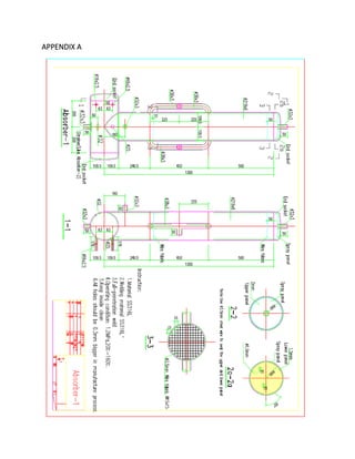
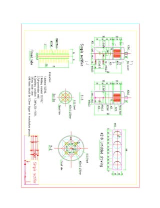
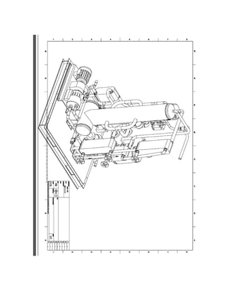
![3.2 ENGINEERING DRAWINGS
This ammonia-sodium thiocyanate absorption system is presented below via
engineering drawings in the Appendix A. Each main component of the system is included,
as well as the assembly drawings.
4.0 CONCLUSION
This report outlined the basic operations of a thermal driven absorption system as well as
comparing the different types of working fluids that are used. It also focused on an absorption
system that uses a new sorbent-sorptive pair: ammonia and sodium thiocyanate.
5.0 REFERENCES
[1] L. Zhu, S. Wang and J. Gu, "Performance Investigation of a Thermal-Driven Refrigeration System," Wiley
InterScience, 2008.
[2] S. Alsaqoor and K. S. AlQdah, "Performance of a Refrigeration Absorption Cycle Driven by Different Power
Sources," Smart Grid and Renewable Energy, 2014.
[3] D. S., W. R. Z., L. P., X. Z. Z., P. Q.W. and X. S.C., "Experimental Studies on an Air-Cooled Two-Stage NH3-
H2O solar absorption air-conditioning prototype," Institute of Refrigeration and Cryogenics, Shangai Jiao Tong
University, Shanghai, 2012.
[4] Machine History, "Solar Powered Air Conditioning," [Online]. Available: http://www.machine-
history.com/Solar%20Powered%20Air%20Conditioning#Absorption:%20NH3/H2O%20or%20Ammonia/Water.
[Accessed April 2015].
[5] I. Boian, A. Serban, S. Fota and F. Chiriac, "NH3 – H2O Absorption Systems Used for Research and Student
Activities," Transylvania University of Brasov, Brasov.](https://image.slidesharecdn.com/221f10d1-2a53-430d-a0d6-6bda2acaca6d-160113212407/85/Cooling-and-Moisture-Control-System-10-320.jpg)