Downloaded 10 times
![International Journal of Mechanical Engineering and Technology (IJMET), ISSN 0976 – 6340(Print),
ISSN 0976 – 6359(Online), Volume 5, Issue 7, July (2014), pp. 42-50 © IAEME
46
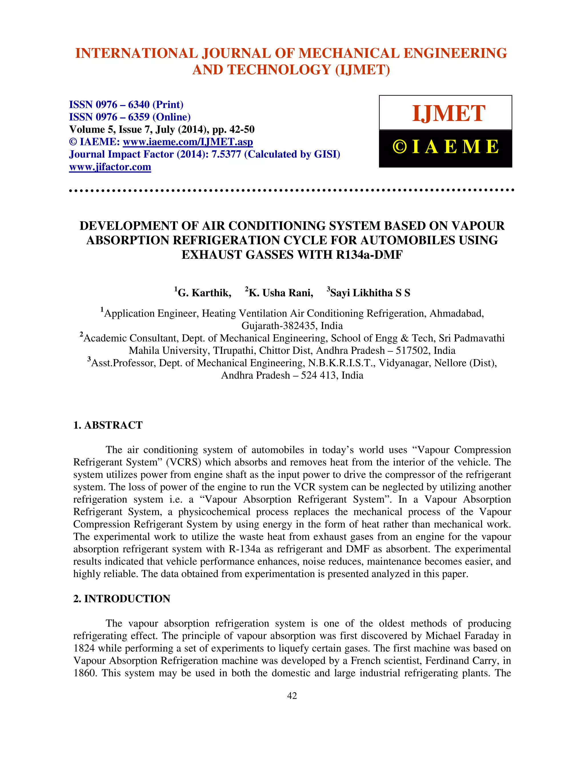
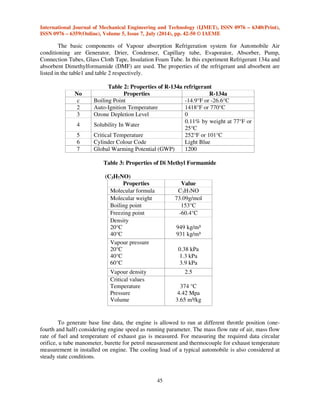
4. CALCULATIONS
For design considerations we have to take assumptions which are based on the basis of
normal summer ambient weather/temperature conditions as well as the temperature to be maintained
at Evaporator Coil is also assumed to be maintained for human comfort.
Table 4: Design consideration of automobile air conditioning unit based on vapour absorption
refrigeration system (CAPACITY=1TR)
Temp
(°C)
Temp
(K)
Press
ure
(bar)
Specific
Enthalpy
(kJ/kg)
Specific Entropy
(kJ/kg K)
Enthalpy
(kJ/kg)
Liquid
(hf)
Latent
(hfg)
Liquid
(sf)
Vapour
(sg)
Liq+Vap
(hg)
Absorber
(T_A)
33
306
5.4
228 409
1.0885 1.7190
181
Generator
(T_G)#
90
363
9.2
254 418
1.1809 1.7122
164
Condenser
(T_C)
38
311
9.2
254 418
1.1809 1.7122
164
Evaporator
(T_E)
19
292
5.4
228 409
1.0885 1.7190
181
Calculations based up on Human comfort.
(For ease of calculation and compactness of the model we have made all of our calculations, taking
Capacity = 1TR)
Coefficient of Performance (COP) = [ ]= 2.41
Workdone (Winput) = [ ]= 87.02 kj/min = 1.45 kw
Mass of Refrigerant Flowing (mf) = = 0.78 kg/min
Volume of Refrigerant Flowing (vf) = ) = 0.000059 m3/sec
Power Required to Drive Suction Pump = = 26 W](https://image.slidesharecdn.com/30120140507005-140924025042-phpapp01/85/30120140507005-5-320.jpg)
![International Journal of Mechanical Engineering and Technology (IJMET), ISSN 0976 – 6340(Print),
ISSN 0976 – 6359(Online), Volume 5, Issue 7, July (2014), pp. 42-50 © IAEME
of which only the pump consumes some power that too is very feeble as compared to that of the
Compressor, and thus helps in saving of fuel.
50
This system can be employed to commercial heavy vehicles including those which are
involved in the transportation of refrigerated products, as this system can easily provide the
refrigeration/air-conditioning of cabin as per the requirements by using the exhaust heat of the
vehicle’s engine (which is in abundance in such vehicles) thus will not add any additional engine to
run the air-conditioning/refrigerating unit in vehicle and hence reduces the operational cost. All in
all, it can be a very well and economical asset for the automobile and can completely change the
scenario of Automobile Air-Conditioning System.
In case of vapour compression refrigeration system an amount of 15% engine work is
required to drive the refrigeration motor. The present investigation has successfully saved this work
by replacing vapour compression refrigeration system with Vapour Absorption Refrigeration
System. The COP of Vapour Absorption Refrigeration System developed by the present project is
2.41 and the lower temperature achieved is 19oC.
REFERENCES
[1] Alam Shah (2006), A Proposed Model for Utilizing Exhaust Heat to run Automobile Air-conditioner,
The 2nd Joint International Conference on “Sustainable Energy and
Environment (SEE 2006)” 21-23 Nov; 2006, Bangkok, Thailand.
[2] G Vicatos, J Gryzagoridis, S Wang, Department of Mechanical Engineering, University of
Cape Town, A car air-conditioning system based on an absorption refrigeration cycle using
energy from exhaust gas of an internal combustion engine. “Journal of Energy in Southern
Africa (Vol 19 No 4), November 2008”
[3] M. Hosoz , M. Direk, Department of Mechanical Education, Kocaeli University, Umuttepe,
41100 Kocaeli, Turkey, Performance evaluation of an integrated automotive air conditioning
and heat pump system “Received 5 November 2004; accepted 18 May 2005 Available online
14 July 2005.” Energy Conversion and Management 47 (2006) 545–559
[4] Khurmi R S, Gupta J K, Refrigeration and Air Conditioning- 2010, Vapour Absorption
Refrigeration (Pg 238-249).
[5] Ganeshan V, Internal Combustion Engine- 2010, Heat Rejection Cooling (Pg 445-467)
[6] Domkundwar Domkundwar, Refrigeration Air-Conditioning Data book.
[7] K.Ganesh Babu, K.Ravi Kumar and Dr. Md. Azizuddin, “Performance Improvement by
Reducing Compressor Work of R-134a and R22 used Refrigeration Systems by using Two-
Phase Ejector”, International Journal of Advanced Research in Engineering Technology
(IJARET), Volume 4, Issue 3, 2013, pp. 187 - 193, ISSN Print: 0976-6480, ISSN Online:
0976-6499.
[8] Dr. Ashok G. Matani and Mukesh K. Agrawal, “Performance Analysis of Vapour
Compression Refrigeration System using R134a, Hc Mixture and R401a as Working
Medium”, International Journal of Mechanical Engineering Technology (IJMET),
Volume 4, Issue 2, 2013, pp. 112 - 126, ISSN Print: 0976 – 6340, ISSN Online: 0976 – 6359.
[9] Anirban Sur and Dr.Randip.K.Das, “Review on Solar Adsorption Refrigeration Cycle”,
International Journal of Mechanical Engineering Technology (IJMET), Volume 1, Issue 1,
2010, pp. 190 - 226, ISSN Print: 0976 – 6340, ISSN Online: 0976 – 6359.](https://image.slidesharecdn.com/30120140507005-140924025042-phpapp01/85/30120140507005-9-320.jpg)

The document discusses the development of a vapor absorption refrigeration system for automobile air conditioning that uses waste heat from engine exhaust, utilizing R-134a as the refrigerant and DMF as the absorbent. This system is shown to improve vehicle performance and reduce engine power consumption compared to conventional vapor compression systems, which require significant energy and may decrease engine life. The findings indicate a coefficient of performance (COP) of 2.41, suggesting a more economical and efficient option for vehicle air conditioning.


![[IJET-V1I6P8] Authors: Priyanka Bonde ,R.R.Borase,J.G.Patil](https://cdn.slidesharecdn.com/ss_thumbnails/ijet-v1i6p8-151213093225-thumbnail.jpg?width=640&height=640&fit=bounds)


