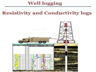
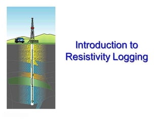
4. WELL LOGGING
• Well logging, also known as borehole logging is
the practice of making a detailed record of the
geologic formations penetrated by a borehole.
• Well logging is performed in boreholes drilled for
the oil and gas, groundwater, mineral and
geothermal exploration, as well as part of
environmental and geotechnical studies.
5.
6. INTRODUCTION
• Resistivity Log is a relationship that exists
between Rock resistivity and both porosity
and saturation.
• A rock which contains an oil and/or gas
saturation will have a higher resistivity
than the same rock completely saturated
with formation water.
7. RESISTIVITY
• Resistivity is an intensive rock/fluid
property, and is a measure of (the inverse
of) the electrical flow capacity of the rock
• Resistance is extensive and for linear, 1-D
electrical flow,
• r=(R ·L)/A
• r electrical resistance, (Ohm)
• R electrical resistivity, (Ohm.m)
• L length of electrical flow path, m
• A cross-sectional area perpendicular to electrical flow path, m2
9. RESISTIVITY
• Example: For a rock cube with sides
of 1 m, if electrical potential of 1 V
(Volt) is required for current flow of 1
A (Ampere), then resistivity is 1
Ohm·m (Ohm ·meter)
11. RESISTIVITY OF EARTH
MATERIALS
• Rock
• Gas
• Oil
• Fresh Water
• Salt Water
• Here resistivity increases from bottom to top
and conductance increases from top to
bottom
12. • Common Notations:
• Ro = Resistivity of non-shaly rock
• Rt = True formation resistivity (ohm-m)
• Rw= Formation water resistivity (ohm-m)
13. Factors affecting the
Electrical Resistivity
• Resistivity of water
• Porosity of the formation
• Pore geometry
• Lithology of the formation
• Degree of cementation
• Type and amount of clay in the rock
14. RESISTIVITY LOGGING
• It is also called Electric logging.
• Resistivity logging measures the subsurface
electrical resistivity.
• The resistivity of a formation is a key parameter
in determining hydrocarbon saturation.
• Electricity can pass through a formation only
because of the conductive water it contains.
• Sub-surface formations have finite, measurable
resistivities because of the water in their pores or
absorbed in their interstitial clay.
15. • Formation resistivities are usually from 0.2 to
1000 ohm-m.
• Resistivities higher than 1000 ohm-m are un-
common in permeable formations but are
observed in impervious, very low porosity (e.g.
evaporites) formations.
• Formation resistivities are measured by either
sending current into the formation and measuring
the ease of the electrical flow through it or by
inducing an electric current into the formation and
measuring how large it is.
16. MEASUREMENTS
• Having the Active Measurements
• High deep resistivity means:
Hydrocarbons
Tight streak
• Low deep resistivity means:
Shale
Wet sand
• Separation between the resistivity means:
Formation fluid is different from the drilling fluid
• Deep, medium and shallow refers the how deep
the formation the resistivity is reading.
17. • Current were passed through the formation by means of
current electrodes, and voltages were measured
between measure electrodes. These measured voltages
provided the resistivity determinations for each device.
• In a homogeneous isotropic formation if infinite extent,
the equipotential surfaces surrounding a single current-
emitting electrode (A) are spheres. The voltage between
an electrode (M) situated on one of these spheres and
one at infinity is proportional to the resistivity of the
homogeneous formation, and the measured voltage can
be scaled in resistivity units.
PRINCIPAL
18. RESISTIVITY DEVICES
NORMAL DEVICE:
• In the normal device a current of constant intensity
is passed between two electrodes, A and B. The
resultant potential difference is measured between
two other electrodes, M and N. Electrodes A and M
are in the subsurface. B and N are, theoretically,
located an infinite distance away at surface. The
distance AM is called the spacing and the point of
inscription for the measurement is at 0. mid- way
between A and M.
• Arrangement is shown in figure.
20. RESISTIVITY DEVICES
LATERAL DEVICE
In the basic lateral device a constant current is
passed between A and B, and the potential
difference between M and N, located on two
concentric spherical equipotential surfaces
centered on A, is measured. Thus, the voltage
measured is proportional to the potential
gradient between M and N. The point of
inscription is at 0, midway between M and N.
22. SCALE
A problem common to all resistivity and
conductivity devices is providing a scale that
can be read accurately over the full range of
response. Years ago, most laterologs were
recorded on linear scales. Because of the
very large range of resistivities often
encountered, the required scale was relatively
insensitive. Very low readings, whether
resistivity or conductivity, were virtually
unreadable.
23. Backup curves of increased sensitivity were
introduced, but they were difficult to read
and cluttered the log in formations of high
contrast.
Today the Logarithmic scale for recording
resistivity curves. Its standard form is a split
four-cycle grid covering the range from 0.2
to 2000 Ohm-meter, as shown in below
figure.
24.
25. APPLICATIONS/USES
• Resistivity measurements are used to calculate
water saturation.(i.e. Saline water has small R,
Petroleum has large R).
• Locate Hydrocarbons.
• Lithology and stratigraphic correlations of
Aquifer and associated rocks.
• Chemical and Physical characteristics of water.
• For Salinity, Viscosity, Effective Porosity, type of
water etc.
26. • Greater spacing of electrodes allows greater
penetration into Formation.
• Induction tools uses coils instead of electrodes
and sets up field to determine Conductivity and
thus Resistivity, gives deep penetration to
approximate Rt.
• Modern tools allow measurement of Horizontal
and vertical resistivity.
27. LIMITATIONS
• Responses in permeable zones depend on
nature of mud.
• Most water-based muds have low resistivity
and oil-based muds have resistivity like that
of petroleum.
• Distance of penetration of mud filtrate varies
with permeability and with mud type.
• Strata that are thin relatively to spacing of
electrodes can give counter-intuitive
responses.