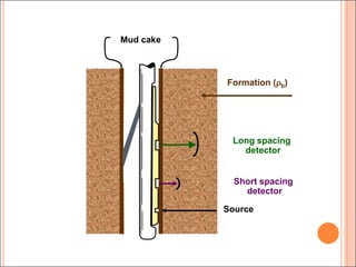
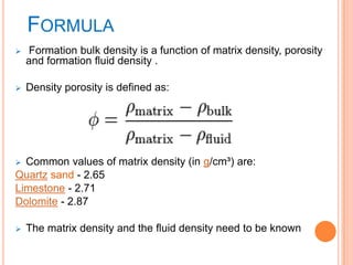
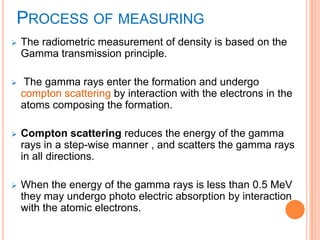
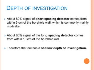
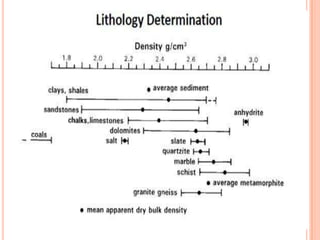
FORMATION DENSITY LOG
Suchitra Laishram
Msc II year
Department of Geology
GR
API0 200
CALIX
IN6 16
CALIY
IN6 16
RHOB
G/C32 3
DRHO
G/C3-0.25 0.25
4100
4200
DEFINITION
 Formation Density logging is a well logging tool
that can provide a continuous record of a
formation's bulk density along the length of a
borehole.
 This is one of three well logging tools that are
commonly used to calculate porosity, the other two
being sonic logging and neutron porosity logging.
HISTORY AND PRINCIPLE
 The tool was initially developed in the 1950s and
was in use throughout the hydrocarbon industry by
the 1960s.
 A type of active nuclear tool, a radioactive source
and detector are lowered down the borehole and
the source emits medium-energy gamma rays into
the formation.
 These gamma rays interact with electrons in the
formation and are scattered in an interaction known
as Compton scattering.
USES OF FORMATION DENSITY LOG
 This method is the most reliable porosity indicator
for sandstones and limestones because their
density is well-known.
 On the other hand the density of clay minerals such
as mudstone is highly variable, depending on
depositional environment, overburden
pressure, type of clay mineral and many other
factors.
 Its main use is to derive a value for the total porosity of
the formation.
 It s also useful in the detection of gas-bearing
formations and in the recognition of evaporites.
 •The combination of formation density log data with
neutron log data gives one of the best ways of
identifying lithologies in a borehole.
DENSITY LOG
 Advantage:
-- Automatically compensates for mudcake and minor
borehole irregularities.
 Limitations:
-- Correction valid only if mudcake or standoff < 0.75”
and is uniform along pad.
-- Abnormally low density (high porosity) in washed out (>
17”) hole or rough hole.
Formation (b)
Long spacing
detector
Short spacing
detector
Mud cake
Source
FORMULA
 Formation bulk density is a function of matrix density, porosity
and formation fluid density .
 Density porosity is defined as:
 Common values of matrix density (in g/cm³) are:
Quartz sand - 2.65
Limestone - 2.71
Dolomite - 2.87
 The matrix density and the fluid density need to be known
TOOLS CONSISTS OF :
 A radioactive source: usually caesium-137 or cobalt-60,
and emits gamma rays of medium energy (in the range
0.2 – 2 MeV). For example, caesium-137 emits gamma
rays with a energy of 0.662 MeV.
 A short range detector. This detector is very similar to the
detectors used in the natural gamma ray tools,and is
placed 7 inches from the source.
 A long range detector. This detector is identical to the
short range detector, and is placed 16 inches from the
source.
PROCESS OF MEASURING
 The radiometric measurement of density is based on the
Gamma transmission principle.
 The gamma rays enter the formation and undergo
compton scattering by interaction with the electrons in the
atoms composing the formation.
 Compton scattering reduces the energy of the gamma
rays in a step-wise manner , and scatters the gamma rays
in all directions.
 When the energy of the gamma rays is less than 0.5 MeV
they may undergo photo electric absorption by interaction
with the atomic electrons.
 The flux of gamma rays that reach each of the two
detectors is therefore attenuated by the formation, and
the amount of attenuation is dependent upon the density
of electrons in the formation.
 The extent to which it is attenuated is directly proportional
to the density of the measured material.
 Moreover the measurement performance is not affected
by temperature, pressure, viscosity, color or chemical
properties of the measured material.
 A formation with a high bulk density, has a high number
density of electrons. It attenuates the gamma rays
significantly, and hence a low gamma ray count rate is
recorded at the sensors.
 A formation with a low bulk density, has a low number
density of electrons. It attenuates the gamma rays less
than a high density formation, and hence a higher gamma
ray count rate is recorded at the sensors.
DEPTH OF INVESTIGATION
 About 80% signal of short spacing detector comes from
within 5 cm of the borehole wall, which is commonly mainly
mudcake .
 About 80% signal of the long spacing detector comes
from within 10 cm of the borehole wall.
 Therefore the tool has a shallow depth of investigation.
LOG PRESENTATION
 The formation density log is recorded in tracks 2 and 3 of
the standard API log presentation on a linear scale.
 The scale is usually spans 1.95 to 2.95 g/cm3 as this is the
normal range for rocks.
THE FORMATION DENSITY TOOL IS MOST OFTEN
RUN IN COMBINATION WITH
a) Gamma ray log : used in mining, mineral exploration, water-
well drilling, for formation evaluation in oil and gas well drilling
and for other related purposes.
b) Caliper log : provides a continuous measurement of the size
and shape of a borehole along its depth.
c) Neutron log : responds primarily to the amount of hydrogen in
the formation which is contained in oil, natural gas, and water.
------ the interpretation of the formation density tool together with
the results from the neutron log provide one of the two best
lithological assessmenttechniques for a reservoir.
VERTICAL RESOLUTION
 The vertical resolution at the typical logging speed
(1300 ft/hr)is good which is defined by the
distance between the two detectors.
 The high vertical resolution means that the log
is useful for defining formation boundaries.
BOREHOLE QUALITY
 The log is run eccentredin the borehole, and therefore is
prone to cavingand rough borehole wallswhere the detectors
or the source may not be pressed against the borehole wall.
 In this case the readings will be erroneous due to radiation
leakage along the borehole between the detectors and bad
measurement geometry.
DRILLING MUD EFFECT
 Drilling muds with high density or that absorb
gamma rays efficiently, such as barite filled muds ,
will effect the detector readings.
 Factors influencing to drilling :
 The change of drilling fluid viscosity.
 The change of drilling fluid density.
 The change of mud pH.
DETERMINATION OF POROSITY
 The porosity of a formation can be obtained from
the bulk density if the mean density of the rock
matrix and that of the fluids it contains are known.
IDENTIFICATION OF LITHOLOGY
 Formation density is not a useful tool for identifying
lithology alone since most sedimentary rocks can have a
range of densities that commonly overlap.
 When used in combination with the neutron log, lithology
can be determined.
 Evaporites are usually very pure and have consistent
densities, making them more easily identifiable the other
sedimentary rocks.
SHALE EFFECT IN DENSITY
MEASUREMENT
 Shale undergoes progressive compaction and increasing
density with depth of burial and age.
 If, within a given shale interval, there is a sudden change
of density, the most likely explanation is that the
formations above and below have been deposited in a
completely different environment. The change is
therefore an indication of a possible unconformity
 The density tool records the bulk density of the formation.
The porosity derived from this will include all pores and
fractures whether they are connected or not.
 Fracture identification and evaluation using conventional
resistivity and compressional -wave acoustic logs is
difficult, in part because fracture recognition is very
dependent on the dip angle of fractures with respect to
the borehole.
FRACTURE RECOGNITION
 The density tool records the bulk density of the
formation. The porosity derived from this will include all
pores and fractures whether they are connected or not.
 Fracture identification and evaluation using conventional
resistivity and compressional -wave acoustic logs is
difficult, in part because fracture recognition is very
dependent on the dip angle of fractures with respect to
the borehole.
 The sonic tool can also be used to measure the porosity of
the formation. However, the sonic tool is not sensitive to
fracture porosity.
 Hence, the difference between the porosities derived from
these two measurements can be used as an indicator of
the extent of fracturing in a reservoir interval.
ORGANIC CONTENT OF SOURCE
ROCKS
 The presence of organic matter can reduce the density of
shales by up to 0.5 g/cm3.It is possible to calculate the
total organic carbon (TOC) content of a source rock from
the change in bulk density.
CONCLUSIONS
 The objective of this project is to compare and determine
the most reliable logging tool for the derivation of the
porosity of a formation using statistical analysis.
 Combined with a detailed quality control system making
use of the multitude of collocated and nearly collocated
measurements it is possible to assess the quality of the
new measurement and its limitations.
REFERENCE
 Class notes
 Wikipedia
 Google
Formation density log

Formation density log

  • 1.
    FORMATION DENSITY LOG SuchitraLaishram Msc II year Department of Geology GR API0 200 CALIX IN6 16 CALIY IN6 16 RHOB G/C32 3 DRHO G/C3-0.25 0.25 4100 4200
  • 2.
    DEFINITION  Formation Densitylogging is a well logging tool that can provide a continuous record of a formation's bulk density along the length of a borehole.  This is one of three well logging tools that are commonly used to calculate porosity, the other two being sonic logging and neutron porosity logging.
  • 3.
    HISTORY AND PRINCIPLE The tool was initially developed in the 1950s and was in use throughout the hydrocarbon industry by the 1960s.  A type of active nuclear tool, a radioactive source and detector are lowered down the borehole and the source emits medium-energy gamma rays into the formation.  These gamma rays interact with electrons in the formation and are scattered in an interaction known as Compton scattering.
  • 4.
    USES OF FORMATIONDENSITY LOG  This method is the most reliable porosity indicator for sandstones and limestones because their density is well-known.  On the other hand the density of clay minerals such as mudstone is highly variable, depending on depositional environment, overburden pressure, type of clay mineral and many other factors.
  • 5.
     Its mainuse is to derive a value for the total porosity of the formation.  It s also useful in the detection of gas-bearing formations and in the recognition of evaporites.  •The combination of formation density log data with neutron log data gives one of the best ways of identifying lithologies in a borehole.
  • 6.
    DENSITY LOG  Advantage: --Automatically compensates for mudcake and minor borehole irregularities.  Limitations: -- Correction valid only if mudcake or standoff < 0.75” and is uniform along pad. -- Abnormally low density (high porosity) in washed out (> 17”) hole or rough hole.
  • 7.
    Formation (b) Long spacing detector Shortspacing detector Mud cake Source
  • 8.
    FORMULA  Formation bulkdensity is a function of matrix density, porosity and formation fluid density .  Density porosity is defined as:  Common values of matrix density (in g/cm³) are: Quartz sand - 2.65 Limestone - 2.71 Dolomite - 2.87  The matrix density and the fluid density need to be known
  • 9.
    TOOLS CONSISTS OF:  A radioactive source: usually caesium-137 or cobalt-60, and emits gamma rays of medium energy (in the range 0.2 – 2 MeV). For example, caesium-137 emits gamma rays with a energy of 0.662 MeV.  A short range detector. This detector is very similar to the detectors used in the natural gamma ray tools,and is placed 7 inches from the source.  A long range detector. This detector is identical to the short range detector, and is placed 16 inches from the source.
  • 10.
    PROCESS OF MEASURING The radiometric measurement of density is based on the Gamma transmission principle.  The gamma rays enter the formation and undergo compton scattering by interaction with the electrons in the atoms composing the formation.  Compton scattering reduces the energy of the gamma rays in a step-wise manner , and scatters the gamma rays in all directions.  When the energy of the gamma rays is less than 0.5 MeV they may undergo photo electric absorption by interaction with the atomic electrons.
  • 11.
     The fluxof gamma rays that reach each of the two detectors is therefore attenuated by the formation, and the amount of attenuation is dependent upon the density of electrons in the formation.  The extent to which it is attenuated is directly proportional to the density of the measured material.  Moreover the measurement performance is not affected by temperature, pressure, viscosity, color or chemical properties of the measured material.
  • 12.
     A formationwith a high bulk density, has a high number density of electrons. It attenuates the gamma rays significantly, and hence a low gamma ray count rate is recorded at the sensors.  A formation with a low bulk density, has a low number density of electrons. It attenuates the gamma rays less than a high density formation, and hence a higher gamma ray count rate is recorded at the sensors.
  • 13.
    DEPTH OF INVESTIGATION About 80% signal of short spacing detector comes from within 5 cm of the borehole wall, which is commonly mainly mudcake .  About 80% signal of the long spacing detector comes from within 10 cm of the borehole wall.  Therefore the tool has a shallow depth of investigation.
  • 14.
    LOG PRESENTATION  Theformation density log is recorded in tracks 2 and 3 of the standard API log presentation on a linear scale.  The scale is usually spans 1.95 to 2.95 g/cm3 as this is the normal range for rocks.
  • 16.
    THE FORMATION DENSITYTOOL IS MOST OFTEN RUN IN COMBINATION WITH a) Gamma ray log : used in mining, mineral exploration, water- well drilling, for formation evaluation in oil and gas well drilling and for other related purposes. b) Caliper log : provides a continuous measurement of the size and shape of a borehole along its depth. c) Neutron log : responds primarily to the amount of hydrogen in the formation which is contained in oil, natural gas, and water. ------ the interpretation of the formation density tool together with the results from the neutron log provide one of the two best lithological assessmenttechniques for a reservoir.
  • 17.
    VERTICAL RESOLUTION  Thevertical resolution at the typical logging speed (1300 ft/hr)is good which is defined by the distance between the two detectors.  The high vertical resolution means that the log is useful for defining formation boundaries.
  • 18.
    BOREHOLE QUALITY  Thelog is run eccentredin the borehole, and therefore is prone to cavingand rough borehole wallswhere the detectors or the source may not be pressed against the borehole wall.  In this case the readings will be erroneous due to radiation leakage along the borehole between the detectors and bad measurement geometry.
  • 19.
    DRILLING MUD EFFECT Drilling muds with high density or that absorb gamma rays efficiently, such as barite filled muds , will effect the detector readings.  Factors influencing to drilling :  The change of drilling fluid viscosity.  The change of drilling fluid density.  The change of mud pH.
  • 20.
    DETERMINATION OF POROSITY The porosity of a formation can be obtained from the bulk density if the mean density of the rock matrix and that of the fluids it contains are known.
  • 22.
    IDENTIFICATION OF LITHOLOGY Formation density is not a useful tool for identifying lithology alone since most sedimentary rocks can have a range of densities that commonly overlap.  When used in combination with the neutron log, lithology can be determined.  Evaporites are usually very pure and have consistent densities, making them more easily identifiable the other sedimentary rocks.
  • 24.
    SHALE EFFECT INDENSITY MEASUREMENT  Shale undergoes progressive compaction and increasing density with depth of burial and age.  If, within a given shale interval, there is a sudden change of density, the most likely explanation is that the formations above and below have been deposited in a completely different environment. The change is therefore an indication of a possible unconformity
  • 25.
     The densitytool records the bulk density of the formation. The porosity derived from this will include all pores and fractures whether they are connected or not.  Fracture identification and evaluation using conventional resistivity and compressional -wave acoustic logs is difficult, in part because fracture recognition is very dependent on the dip angle of fractures with respect to the borehole.
  • 26.
    FRACTURE RECOGNITION  Thedensity tool records the bulk density of the formation. The porosity derived from this will include all pores and fractures whether they are connected or not.  Fracture identification and evaluation using conventional resistivity and compressional -wave acoustic logs is difficult, in part because fracture recognition is very dependent on the dip angle of fractures with respect to the borehole.
  • 27.
     The sonictool can also be used to measure the porosity of the formation. However, the sonic tool is not sensitive to fracture porosity.  Hence, the difference between the porosities derived from these two measurements can be used as an indicator of the extent of fracturing in a reservoir interval.
  • 28.
    ORGANIC CONTENT OFSOURCE ROCKS  The presence of organic matter can reduce the density of shales by up to 0.5 g/cm3.It is possible to calculate the total organic carbon (TOC) content of a source rock from the change in bulk density.
  • 29.
    CONCLUSIONS  The objectiveof this project is to compare and determine the most reliable logging tool for the derivation of the porosity of a formation using statistical analysis.  Combined with a detailed quality control system making use of the multitude of collocated and nearly collocated measurements it is possible to assess the quality of the new measurement and its limitations.
  • 30.
    REFERENCE  Class notes Wikipedia  Google