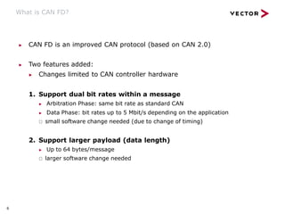
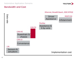
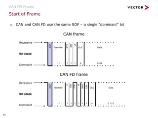
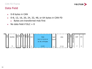
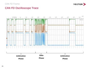
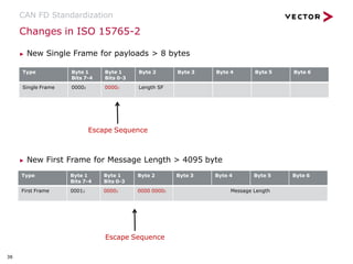
V1.02 | 2018-10-11
An Introduction
CAN FD
▶ Why CAN FD?
What is CAN FD?
CAN FD Use Cases
Automotive Application Domains
CAN FD Frame
CAN FD Controller
CAN FD Performance
CAN FD Devices
CAN FD Standardization
Summary
References
Agenda
3
Why CAN FD?
Many CAN buses have reached 50 % … 95 % network load level
1. Network speed limited to 1 Mbit/s (typical ≤ 500 kbit/s)
▶ Limited by physical characteristics of in-vehicle wiring due to the
In-Frame response mechanism:
▶ ACK generation delay in CAN controller
▶ Propagation delay through the transceiver
▶ Propagation delay over wire
2. CAN messages contain ≥ 50 % overhead
▶ Other protocols have less overhead
▶ Ethernet UDP – ~1500 bytes/datagram, 64 bytes overhead (IPv4)
▶ FlexRay – 254 bytes/frame, 8 bytes of overhead
CAN_H
CAN_L
CAN ECU
RT
CAN ECU
Why CAN FD?
▶ What is CAN FD?
CAN FD Use Cases
Automotive Application Domains
CAN FD Frame
CAN FD Controller
CAN FD Performance
CAN FD Devices
CAN FD Standardization
Summary
References
Agenda
What is CAN FD?
6
▶ CAN FD is an improved CAN protocol (based on CAN 2.0)
▶ Two features added:
▶ Changes limited to CAN controller hardware
1. Support dual bit rates within a message
▶ Arbitration Phase: same bit rate as standard CAN
▶ Data Phase: bit rates up to 5 Mbit/s depending on the application
🢂 small software change needed (due to change of timing)
2. Support larger payload (data length)
▶ Up to 64 bytes/message
🢂 larger software change needed
What is CAN FD?
▶ System cost similar to standard CAN
▶ Controller, crystal, transceiver, node interconnection cost
▶ Existing CAN transceivers usable up to 2-5 Mbit/s depending on the
application
▶ Well known technology: Event triggered system
▶ Smooth migration at reasonable cost possible
▶ Classic CAN and CAN FD ECUs can be mixed under certain conditions
7
Combining CAN and CAN FD
What is CAN FD?
Scenario 1
▶ Some nodes are not CAN FD capable:
▶ Communicate only with classic CAN messages or switch off the not-
capable nodes (e.g. during flashing)
> Partial network transceiver
> Sophisticated filter transceivers (e.g. NXP Shield Transceiver)
Scenario 2
▶ All nodes are CAN FD capable:
▶ Classic and FD messages can be mixed
8
Combining CAN and CAN FD
What is CAN FD?
Transmit Classical FD
Classical
FD
Receive
9
Why CAN FD?
What is CAN FD?
▶ CAN FD Use Cases
Automotive Application Domains
CAN FD Frame
CAN FD Controller
CAN FD Performance
CAN FD Devices
CAN FD Standardization
Summary
References
Agenda
11
CAN FD Use Cases
▶ Faster software download
▶ Avoid split of data into several frames
▶ Decrease bus load of an existing bus
▶ Increase no. of ECUs on the bus
▶ Avoid split of networks
▶ Accelerate communication on long bus lines
(truck/bus)
Why CAN FD?
What is CAN FD?
CAN FD Use Cases
▶ Automotive Application Domains
CAN FD Frame
CAN FD Controller
CAN FD Performance
CAN FD Devices
CAN FD Standardization
Summary
References
Agenda
Bandwidth and Cost
Automotive Application Domains
Implementation cost
Data
rate
Sensors &
actuators
Convenience
Powertrain &
chassis
Assistance &
X-by-wire
LIN
13
CAN LS
CAN HS
FlexRay
Driver
Assistance
Infotainment
MOST150
Ethernet, BroadR-Reach, IEEE RTPGE
CAN FD
Automotive Application Domains
CAN FD vs. FlexRay
▶ CAN FD closes the gap between classic CAN
(1 MBit/s) and FlexRay (10 MBit/s) but
▶ Higher effort for FlexRay migration
▶ FlexRay is less flexible but offers high predictability
(bus load, …)
▶ FlexRay is not efficient for ECU flashing
CAN FD vs. Ethernet
▶ Ethernet provides the necessary bandwidth e.g.
for Car2x, and camera applications
▶ Higher effort for Ethernet migration
▶ Ethernet (UDP) more efficient for streaming
applications
▶ Event triggered system vs. switched network
14
Why CAN FD?
What is CAN FD?
CAN FD Use Cases
Automotive Application Domains
▶ CAN FD Frame
CAN FD Controller
CAN FD Performance
CAN FD Devices
CAN FD Standardization
Summary
References
Agenda
Arbitration Phase and Data Phase
CAN FD Frame
CAN FD Frame
Arbitration Phase
(standard bit rate)
Arbitration Phase
(standard bit rate)
Data Phase
(optional high bit rate)
CAN FD Extended Frame
Arbitration Phase Data Phase Arbitration Phase
SOF
1
CRC
Delimiter
ACK
ACK
Delimiter
1
RRS
IDE
FDF
res
BRS
ESI
1
1 1 1 1 1 1 1
Identifier
11
DLC
4
Data
0..512
CRC
17 / 21 7
EOF IFS
3
Stuff
Count
4
1
1 1
1 7
1
1
1
SOF
CRC
Delimiter
ACK
ACK
Delimiter
RRS
FDF
res
BRS
ESI
Identifier
11
DLC
4
Data
0..512
CRC
17 / 21
EOF IFS
3
Extended
Identifier
18
SRR
IDE
1 1 1 1
Stuff
Count
4
16
CAN FD Frame Fields
CAN FD Frame
▶ … and seven different bit fields – SOF, Arbitration, Control,
Data, CRC (Stuff Count + CRC Sequence), ACK, EOF
CAN FD Frame
Arbitration
Field
Start
Of
Frame
Control
Field
Data Field CRC
Field
ACK
Field
End
Of
Frame
SOF
1
CRC
Delimiter
ACK
ACK
Delimiter
1
RRS
IDE
FDF
res
BRS
ESI
1
1 1 1 1 1 1 1
Identifier
11
DLC
4
Data
0..512
CRC
17 / 21 7
EOF IFS
3
Stuff
Count
4
17
Start of Frame
CAN FD Frame
▶ CAN and CAN FD use the same SOF – a single “dominant” bit
CAN frame
Recessive
CAN FD frame
Bit state
Dominant
Recessive
Bit state
Dominant
1
SOF
r1
IDE
FDF
r0
BRS
ESI
Identifier
11
DLC
1 1 1 1 1 1 4
Data
0..512
1
SOF
RTR
IDE
r0
1 1 1
Identifier
11
DLC
4
Data
0..64
18
Arbitration Field
CAN FD Frame
▶ Little difference between CAN and CAN FD arbitration fields
▶ Both share the same addressing for Standard and Extended formats
▶ CAN FD removes the RTR bit and maintains an always dominant
RRS bit
CAN frame
CAN FD frame
Data
0..512
SOF
1
RRS
IDE
FDF
res
BRS
ESI
1
Identifier
11
DLC
1 1 1 1 1 4
SOF
1 1
RTR
r1
r0
1 1
Identifier
11
DLC
4
Data
0..64
19
Control Field
▶ CAN and CAN FD share the following bits:
▶ IDE, res and the DLC bits
CAN FD Frame
▶ CAN FD adds the following bits to the control field:
▶ FDF – FD Format
▶ Determines if CAN (dominant) or CAN FD (recessive)
▶ BRS – Bit Rate Switch
▶ Separates Arbitration Phase from Data Phase in CAN FD
▶ Clock rate switches when BRS is recessive
▶ ESI – Error State Indicator (error active/passive)
1
1 1
SOF
1 RRS
IDE
FDF
res
BRS
ESI
1 1 1
Identifier
11
DLC
4
Data
0..512
20
Control Field: DLC
▶ Data Length Code (DLC)
▶ 4 bits used for both formats
▶ CAN FD compatible with CAN at data lengths ≤ 7
▶ CAN ignores 3 lsb if DLC = 8, CAN FD does not
▶ For lengths ≥ 8, CAN FD uses the following DLCs:
CAN FD Frame
1000 = 8 1100 = 24
1001 = 12 1101 = 32
1010 = 16 1110 = 48
1011 = 20 1111 = 64
CRC
17 / 21
SOF
1
CRC
Delimiter
ACK
ACK
Delimiter
RRS
IDE
FDF
res
BRS
ESI
1 1 1
Identifier
11
DLC
1 1 1 1 1 1 4
Data
0-8, 12, 16, 20, 24
32, 48, or 64 bytes
0..512 7
EOF IFS
3
Stuff
Count
21
4
Data Field
▶ 0-8 bytes in CAN
▶ 0-8, 12, 16, 20, 24, 32, 48, or 64 bytes in CAN FD
▶ Bytes are transferred msb first
▶ No data field if DLC = 0
CAN FD Frame
SOF
1
CRC
Delimiter
ACK
ACK
Delimiter
RRS
IDE
FDF
res
BRS
ESI
1 1 1
Identifier
11
DLC
1 1 1 1 1 1 4
Data
0-8, 12, 16, 20, 24
32, 48, or 64 bytes
0..512 7
EOF IFS
3
Stuff
Count
22
4
CRC
17 / 21
23
CRC Field: Stuff Count
CAN FD Frame
CRC
Delimiter
ACK
ACK
Delimiter
1 1 1
Data
0..512
CRC
17 / 21 7
EOF IFS
3
Stuff
Count
4
1 1 1
1
Bit
2
Bit
1
Bit
0
Parity
▶ Preceding stuff bits are included in the CAN FD CRC calculation
▶ CAN does not use stuff bits in the CRC calculation
▶ This makes it necessary to transmit the total number of bits.
▶ Therefore the number of dynamic stuff bits is included into the frame format (stuff
bit count modulo 8).
▶ Two safeguards for the Stuff Count are implemented:
▶ 1. Adding a parity-bit (even parity)
▶ 2. Gray-coding the stuff bit count (Bit0-2)
CRC Field: CRC Sequence
CAN FD Frame
▶ Size of CRC differs based on CAN/CAN FD and length of DLC
▶ 15 bits for CAN
▶ 17 bits for CAN FD where data field ≤ 16 bytes
▶ 21 bits for CAN FD where data field > 16 bytes
▶ CAN FD CRC delimiter is always transmitted as 1 bit, but due to phase
shift between nodes a transmitter accepts up to 2 bit times
▶ Data Phase of CAN FD frame ends with the sample point of the first
bit of the CRC delimiter
CRC
Delimiter
ACK
ACK
Delimiter
1 1 1
Data
0..512
CRC
17 / 21 7
EOF IFS
3
Stuff
Count
4
24
ACK Field
CAN FD Frame
▶ ACK sent at the end of the CRC delimiter bit
▶ Slight difference in the format between CAN and CAN FD
▶ CAN FD nodes recognize up to two bit times as a valid ACK
▶ 1 extra bit time allowed to compensate for transceiver phase shift and bus
propagation delay due to the switch from a high Data Phase clock to a low
Arbitration Phase clock
End of Frame
▶ Frames are delimited by a group of 7 recessive bits
CRC
Delimiter
1
C
K
A
te
r i
m
i
D
el
C
K
A
1 1
Data
0..512
CRC
17 / 21 7
EOF IFS
3
Stuff
Count
4
25
CAN FD Oscilloscope Trace
CAN FD Frame
Arbitration
Phase
26
Data
Phase
Arbitration
Phase
Why CAN FD?
What is CAN FD?
CAN FD Use Cases
Automotive Application Domains
CAN FD Frame
▶ CAN FD Controller
CAN FD Performance
CAN FD Devices
CAN FD Standardization
Summary
References
Agenda
CAN FD Controller
28
▶ Controller allows for dynamic switching between CAN – CAN FD
▶ Four Frame Formats:
▶ CAN base format – 11 bit identifier and fixed bit rate
▶ CAN extended format – 29 bit identifier and fixed bit rate
▶ CAN FD base format – 11 bit identifier and dual bit rate
▶ CAN FD extended format – 29 bit identifier and dual bit rate
▶ Error Frame:
▶ Identical to CAN error frame
▶ Error frame is always sent with arbitration bit rate
▶ Controller switches automatically to arbitration bit rate
CAN FD Controller
29
▶ Remote Frame:
▶ Remote frame in CAN base format
▶ Remote frame in CAN extended format
▶ Remote frames are undefined in CAN FD format
▶ RTR bit removed from CAN FD bit-stream
▶ Overload Frame:
▶ Identical to CAN overload frame
▶ Overload frame is always send with arbitration bit rate
Why CAN FD?
What is CAN FD?
CAN FD Use Cases
Automotive Application Domains
CAN FD Frame
CAN FD Controller
▶ CAN FD Performance
CAN FD Devices
CAN FD Standardization
Summary
References
Agenda
CAN FD Performance
31
▶ Basic calculation principles:
▶ Stuff bits excluded
▶ Max CAN frame with 111 bits
▶ Max CAN FD frames with 120/572 bits
▶ CAN FD can decrease bus loading significantly
▶ Data/Overhead ratio increases for 64 byte significantly
Frame Type No. Data Bytes Arb. Bit-Rate Opt. Bit-Rate Avg. Bit-Rate Frame Duration
CAN 8 500 Kbit/s - 222 us
CAN FD 8 500 Kbit/s 2 Mbit/s 1.16 Mbit/s 103.5 us
CAN FD 8 500 Kbit/s 5 Mbit/s 1.57 Mbit/s 76.2 us
CAN FD 64 500 Kbit/s 2 Mbit/s 1.74 Mbit/s 329.5 us
CAN FD 64 500 Kbit/s 5 Mbit/s 3.43 Mbit/s 166.6 us
CAN FD Performance
▶ CAN FD average bit rate converges due to Arbitration Phase
▶ Arbitration phase becomes dominant at a certain baud rate for the Data
Phase.
▶ This means that the overall frame length becomes not much smaller
through a further increase of the Data Phase bit rate.
32
Why CAN FD?
What is CAN FD?
CAN FD Use Cases
Automotive Application Domains
CAN FD Frame
CAN FD Controller
CAN FD Performance
▶ CAN FD Devices
CAN FD Standardization
Summary
References
Agenda
34
CAN FD Devices
CAN Controller
▶ MCUs with full CAN FD support available (ISO)
▶ Freescale, ST, Renesas, Spansion, Infineon …
CAN Transceiver
▶ Typical bit rates of automotive transceivers for CAN FD
▶ Functional messages: 2 Mbit/s
▶ Reprogramming: 5 Mbit/s
▶ Transceivers for CAN FD operation available from different manufacturers
▶ Support of 2 Mbit/s within current emission limits
Why CAN FD?
What is CAN FD?
CAN FD Use Cases
Automotive Application Domains
CAN FD Frame
CAN FD Controller
CAN FD Performance
CAN FD Devices
▶ CAN FD Standardization
Summary
References
Agenda
CAN FD Standardization
CAN ISO 11898
▶ CAN FD as part of ISO 11898-1 (CAN Controller)
> International Standard (IS 2015)
▶ ISO 11898-2 (CAN Transceiver)
> International Standard (IS 2016)
> Substitutes the previous versions of part 2, part 5, and part 6.
> Specifies the transceiver characteristics for bit-rates up to 5 Mbit/s.
CAN ISO 16845
▶ Upgrade of CAN controller conformance test ISO 16845-1
> International Standard (IS 2016)
▶ Upgrade of CAN transceiver conformance test ISO 16845-2
> International Standard (IS 2018)
AUTOSAR
▶ CAN FD (8 byte) in Autosar 4.1.1
▶ CAN FD (64 byte) in Autosar 4.2.1
J1939
▶ CAN FD upgrade  ongoing
36
CAN FD Standardization
ISO 15765-2: ISO TP
▶ ISO transport protocol supports the CAN FD data link layer with data
fields up to 64 byte
▶ International Standard (IS 2016)
CANopen
▶ CiA SIG CANopen is updating the CiA 301 application layer to support
the CAN FD data link layer
37
▶ New Single Frame for payloads > 8 bytes
▶ New First Frame for Message Length > 4095 byte
Changes in ISO 15765-2
CAN FD Standardization
Type Byte 1
Bits 7-4
Byte 1
Bits 0-3
Byte 2 Byte 3 Byte 4 Byte 5 Byte 6
Single Frame 00002 00002 Length SF
Escape Sequence
Type Byte 1
Bits 7-4
Byte 1
Bits 0-3
Byte 2 Byte 3 Byte 4 Byte 5 Byte 6
First Frame 00012 00002 0000 00002 Message Length
Escape Sequence
38
Why CAN FD?
What is CAN FD?
CAN FD Use Cases
Automotive Application Domains
CAN FD Frame
CAN FD Controller
CAN FD Performance
CAN FD Devices
CAN FD Standardization
▶ Summary
References
Agenda
40
Summary
Serial communication networks require increased bandwidth
▶ Due to high bus load levels
▶ For flashing applications
CAN FD can provide significantly increased bandwidth
▶ Due to increased data clock rates
▶ Due to larger data payloads
CAN FD is an improvement of well known CAN technology
▶ Event triggered system
▶ Unchanged arbitration and acknowledge mechanism
Why CAN FD?
What is CAN FD?
CAN FD Use Cases
Automotive Application Domains
CAN FD Frame
CAN FD Controller
CAN FD Performance
CAN FD Devices
CAN FD Standardization
Summary
▶ References
Agenda
42
References
▶ Paper “CAN with Flexible Data Rate” – Florian Hartwich, Robert Bosch
GmbH;CAN in Automation, iCC 2012, March 2012
▶ Presentation “CAN FD CAN with Flexible Data Rate” – Florian Hartwich,
Robert Bosch, GmbH; Feb. 15, 2012
▶ http://www.bosch-semiconductors.com/ip-modules/can-ip-modules/m-can
▶ M_CAN Controller Area Network User’s Manual
▶ http://www.bosch-semiconductors.com/ip-modules/can-ip-modules/can-fd
▶ Papers about bit timing requirements and robustness of CAN FD
networks
▶ Press Articles from Vector:
▶ https://www.vector.com/de/de/know-
how/technologien/netzwerke/can/#c42688
▶ https://www.vector.com/int/en/know-
how/technologies/networks/can/#c9439
© 2018. Vector Informatik GmbH. All rights reserved. Any distribution or copying is subject to prior written approval by Vector. V1.02 | 2018-10-11
Author:
Vector Germany
For more information about Vector
and our products please visit
www.vector.com

CAN_FD_Introduction_ENGLISH VERSION.pptx

  • 1.
    V1.02 | 2018-10-11 AnIntroduction CAN FD
  • 2.
    ▶ Why CANFD? What is CAN FD? CAN FD Use Cases Automotive Application Domains CAN FD Frame CAN FD Controller CAN FD Performance CAN FD Devices CAN FD Standardization Summary References Agenda
  • 3.
    3 Why CAN FD? ManyCAN buses have reached 50 % … 95 % network load level 1. Network speed limited to 1 Mbit/s (typical ≤ 500 kbit/s) ▶ Limited by physical characteristics of in-vehicle wiring due to the In-Frame response mechanism: ▶ ACK generation delay in CAN controller ▶ Propagation delay through the transceiver ▶ Propagation delay over wire 2. CAN messages contain ≥ 50 % overhead ▶ Other protocols have less overhead ▶ Ethernet UDP – ~1500 bytes/datagram, 64 bytes overhead (IPv4) ▶ FlexRay – 254 bytes/frame, 8 bytes of overhead CAN_H CAN_L CAN ECU RT CAN ECU
  • 4.
    Why CAN FD? ▶What is CAN FD? CAN FD Use Cases Automotive Application Domains CAN FD Frame CAN FD Controller CAN FD Performance CAN FD Devices CAN FD Standardization Summary References Agenda
  • 5.
    What is CANFD? 6 ▶ CAN FD is an improved CAN protocol (based on CAN 2.0) ▶ Two features added: ▶ Changes limited to CAN controller hardware 1. Support dual bit rates within a message ▶ Arbitration Phase: same bit rate as standard CAN ▶ Data Phase: bit rates up to 5 Mbit/s depending on the application 🢂 small software change needed (due to change of timing) 2. Support larger payload (data length) ▶ Up to 64 bytes/message 🢂 larger software change needed
  • 6.
    What is CANFD? ▶ System cost similar to standard CAN ▶ Controller, crystal, transceiver, node interconnection cost ▶ Existing CAN transceivers usable up to 2-5 Mbit/s depending on the application ▶ Well known technology: Event triggered system ▶ Smooth migration at reasonable cost possible ▶ Classic CAN and CAN FD ECUs can be mixed under certain conditions 7
  • 7.
    Combining CAN andCAN FD What is CAN FD? Scenario 1 ▶ Some nodes are not CAN FD capable: ▶ Communicate only with classic CAN messages or switch off the not- capable nodes (e.g. during flashing) > Partial network transceiver > Sophisticated filter transceivers (e.g. NXP Shield Transceiver) Scenario 2 ▶ All nodes are CAN FD capable: ▶ Classic and FD messages can be mixed 8
  • 8.
    Combining CAN andCAN FD What is CAN FD? Transmit Classical FD Classical FD Receive 9
  • 9.
    Why CAN FD? Whatis CAN FD? ▶ CAN FD Use Cases Automotive Application Domains CAN FD Frame CAN FD Controller CAN FD Performance CAN FD Devices CAN FD Standardization Summary References Agenda
  • 10.
    11 CAN FD UseCases ▶ Faster software download ▶ Avoid split of data into several frames ▶ Decrease bus load of an existing bus ▶ Increase no. of ECUs on the bus ▶ Avoid split of networks ▶ Accelerate communication on long bus lines (truck/bus)
  • 11.
    Why CAN FD? Whatis CAN FD? CAN FD Use Cases ▶ Automotive Application Domains CAN FD Frame CAN FD Controller CAN FD Performance CAN FD Devices CAN FD Standardization Summary References Agenda
  • 12.
    Bandwidth and Cost AutomotiveApplication Domains Implementation cost Data rate Sensors & actuators Convenience Powertrain & chassis Assistance & X-by-wire LIN 13 CAN LS CAN HS FlexRay Driver Assistance Infotainment MOST150 Ethernet, BroadR-Reach, IEEE RTPGE CAN FD
  • 13.
    Automotive Application Domains CANFD vs. FlexRay ▶ CAN FD closes the gap between classic CAN (1 MBit/s) and FlexRay (10 MBit/s) but ▶ Higher effort for FlexRay migration ▶ FlexRay is less flexible but offers high predictability (bus load, …) ▶ FlexRay is not efficient for ECU flashing CAN FD vs. Ethernet ▶ Ethernet provides the necessary bandwidth e.g. for Car2x, and camera applications ▶ Higher effort for Ethernet migration ▶ Ethernet (UDP) more efficient for streaming applications ▶ Event triggered system vs. switched network 14
  • 14.
    Why CAN FD? Whatis CAN FD? CAN FD Use Cases Automotive Application Domains ▶ CAN FD Frame CAN FD Controller CAN FD Performance CAN FD Devices CAN FD Standardization Summary References Agenda
  • 15.
    Arbitration Phase andData Phase CAN FD Frame CAN FD Frame Arbitration Phase (standard bit rate) Arbitration Phase (standard bit rate) Data Phase (optional high bit rate) CAN FD Extended Frame Arbitration Phase Data Phase Arbitration Phase SOF 1 CRC Delimiter ACK ACK Delimiter 1 RRS IDE FDF res BRS ESI 1 1 1 1 1 1 1 1 Identifier 11 DLC 4 Data 0..512 CRC 17 / 21 7 EOF IFS 3 Stuff Count 4 1 1 1 1 7 1 1 1 SOF CRC Delimiter ACK ACK Delimiter RRS FDF res BRS ESI Identifier 11 DLC 4 Data 0..512 CRC 17 / 21 EOF IFS 3 Extended Identifier 18 SRR IDE 1 1 1 1 Stuff Count 4 16
  • 16.
    CAN FD FrameFields CAN FD Frame ▶ … and seven different bit fields – SOF, Arbitration, Control, Data, CRC (Stuff Count + CRC Sequence), ACK, EOF CAN FD Frame Arbitration Field Start Of Frame Control Field Data Field CRC Field ACK Field End Of Frame SOF 1 CRC Delimiter ACK ACK Delimiter 1 RRS IDE FDF res BRS ESI 1 1 1 1 1 1 1 1 Identifier 11 DLC 4 Data 0..512 CRC 17 / 21 7 EOF IFS 3 Stuff Count 4 17
  • 17.
    Start of Frame CANFD Frame ▶ CAN and CAN FD use the same SOF – a single “dominant” bit CAN frame Recessive CAN FD frame Bit state Dominant Recessive Bit state Dominant 1 SOF r1 IDE FDF r0 BRS ESI Identifier 11 DLC 1 1 1 1 1 1 4 Data 0..512 1 SOF RTR IDE r0 1 1 1 Identifier 11 DLC 4 Data 0..64 18
  • 18.
    Arbitration Field CAN FDFrame ▶ Little difference between CAN and CAN FD arbitration fields ▶ Both share the same addressing for Standard and Extended formats ▶ CAN FD removes the RTR bit and maintains an always dominant RRS bit CAN frame CAN FD frame Data 0..512 SOF 1 RRS IDE FDF res BRS ESI 1 Identifier 11 DLC 1 1 1 1 1 4 SOF 1 1 RTR r1 r0 1 1 Identifier 11 DLC 4 Data 0..64 19
  • 19.
    Control Field ▶ CANand CAN FD share the following bits: ▶ IDE, res and the DLC bits CAN FD Frame ▶ CAN FD adds the following bits to the control field: ▶ FDF – FD Format ▶ Determines if CAN (dominant) or CAN FD (recessive) ▶ BRS – Bit Rate Switch ▶ Separates Arbitration Phase from Data Phase in CAN FD ▶ Clock rate switches when BRS is recessive ▶ ESI – Error State Indicator (error active/passive) 1 1 1 SOF 1 RRS IDE FDF res BRS ESI 1 1 1 Identifier 11 DLC 4 Data 0..512 20
  • 20.
    Control Field: DLC ▶Data Length Code (DLC) ▶ 4 bits used for both formats ▶ CAN FD compatible with CAN at data lengths ≤ 7 ▶ CAN ignores 3 lsb if DLC = 8, CAN FD does not ▶ For lengths ≥ 8, CAN FD uses the following DLCs: CAN FD Frame 1000 = 8 1100 = 24 1001 = 12 1101 = 32 1010 = 16 1110 = 48 1011 = 20 1111 = 64 CRC 17 / 21 SOF 1 CRC Delimiter ACK ACK Delimiter RRS IDE FDF res BRS ESI 1 1 1 Identifier 11 DLC 1 1 1 1 1 1 4 Data 0-8, 12, 16, 20, 24 32, 48, or 64 bytes 0..512 7 EOF IFS 3 Stuff Count 21 4
  • 21.
    Data Field ▶ 0-8bytes in CAN ▶ 0-8, 12, 16, 20, 24, 32, 48, or 64 bytes in CAN FD ▶ Bytes are transferred msb first ▶ No data field if DLC = 0 CAN FD Frame SOF 1 CRC Delimiter ACK ACK Delimiter RRS IDE FDF res BRS ESI 1 1 1 Identifier 11 DLC 1 1 1 1 1 1 4 Data 0-8, 12, 16, 20, 24 32, 48, or 64 bytes 0..512 7 EOF IFS 3 Stuff Count 22 4 CRC 17 / 21
  • 22.
    23 CRC Field: StuffCount CAN FD Frame CRC Delimiter ACK ACK Delimiter 1 1 1 Data 0..512 CRC 17 / 21 7 EOF IFS 3 Stuff Count 4 1 1 1 1 Bit 2 Bit 1 Bit 0 Parity ▶ Preceding stuff bits are included in the CAN FD CRC calculation ▶ CAN does not use stuff bits in the CRC calculation ▶ This makes it necessary to transmit the total number of bits. ▶ Therefore the number of dynamic stuff bits is included into the frame format (stuff bit count modulo 8). ▶ Two safeguards for the Stuff Count are implemented: ▶ 1. Adding a parity-bit (even parity) ▶ 2. Gray-coding the stuff bit count (Bit0-2)
  • 23.
    CRC Field: CRCSequence CAN FD Frame ▶ Size of CRC differs based on CAN/CAN FD and length of DLC ▶ 15 bits for CAN ▶ 17 bits for CAN FD where data field ≤ 16 bytes ▶ 21 bits for CAN FD where data field > 16 bytes ▶ CAN FD CRC delimiter is always transmitted as 1 bit, but due to phase shift between nodes a transmitter accepts up to 2 bit times ▶ Data Phase of CAN FD frame ends with the sample point of the first bit of the CRC delimiter CRC Delimiter ACK ACK Delimiter 1 1 1 Data 0..512 CRC 17 / 21 7 EOF IFS 3 Stuff Count 4 24
  • 24.
    ACK Field CAN FDFrame ▶ ACK sent at the end of the CRC delimiter bit ▶ Slight difference in the format between CAN and CAN FD ▶ CAN FD nodes recognize up to two bit times as a valid ACK ▶ 1 extra bit time allowed to compensate for transceiver phase shift and bus propagation delay due to the switch from a high Data Phase clock to a low Arbitration Phase clock End of Frame ▶ Frames are delimited by a group of 7 recessive bits CRC Delimiter 1 C K A te r i m i D el C K A 1 1 Data 0..512 CRC 17 / 21 7 EOF IFS 3 Stuff Count 4 25
  • 25.
    CAN FD OscilloscopeTrace CAN FD Frame Arbitration Phase 26 Data Phase Arbitration Phase
  • 26.
    Why CAN FD? Whatis CAN FD? CAN FD Use Cases Automotive Application Domains CAN FD Frame ▶ CAN FD Controller CAN FD Performance CAN FD Devices CAN FD Standardization Summary References Agenda
  • 27.
    CAN FD Controller 28 ▶Controller allows for dynamic switching between CAN – CAN FD ▶ Four Frame Formats: ▶ CAN base format – 11 bit identifier and fixed bit rate ▶ CAN extended format – 29 bit identifier and fixed bit rate ▶ CAN FD base format – 11 bit identifier and dual bit rate ▶ CAN FD extended format – 29 bit identifier and dual bit rate ▶ Error Frame: ▶ Identical to CAN error frame ▶ Error frame is always sent with arbitration bit rate ▶ Controller switches automatically to arbitration bit rate
  • 28.
    CAN FD Controller 29 ▶Remote Frame: ▶ Remote frame in CAN base format ▶ Remote frame in CAN extended format ▶ Remote frames are undefined in CAN FD format ▶ RTR bit removed from CAN FD bit-stream ▶ Overload Frame: ▶ Identical to CAN overload frame ▶ Overload frame is always send with arbitration bit rate
  • 29.
    Why CAN FD? Whatis CAN FD? CAN FD Use Cases Automotive Application Domains CAN FD Frame CAN FD Controller ▶ CAN FD Performance CAN FD Devices CAN FD Standardization Summary References Agenda
  • 30.
    CAN FD Performance 31 ▶Basic calculation principles: ▶ Stuff bits excluded ▶ Max CAN frame with 111 bits ▶ Max CAN FD frames with 120/572 bits ▶ CAN FD can decrease bus loading significantly ▶ Data/Overhead ratio increases for 64 byte significantly Frame Type No. Data Bytes Arb. Bit-Rate Opt. Bit-Rate Avg. Bit-Rate Frame Duration CAN 8 500 Kbit/s - 222 us CAN FD 8 500 Kbit/s 2 Mbit/s 1.16 Mbit/s 103.5 us CAN FD 8 500 Kbit/s 5 Mbit/s 1.57 Mbit/s 76.2 us CAN FD 64 500 Kbit/s 2 Mbit/s 1.74 Mbit/s 329.5 us CAN FD 64 500 Kbit/s 5 Mbit/s 3.43 Mbit/s 166.6 us
  • 31.
    CAN FD Performance ▶CAN FD average bit rate converges due to Arbitration Phase ▶ Arbitration phase becomes dominant at a certain baud rate for the Data Phase. ▶ This means that the overall frame length becomes not much smaller through a further increase of the Data Phase bit rate. 32
  • 32.
    Why CAN FD? Whatis CAN FD? CAN FD Use Cases Automotive Application Domains CAN FD Frame CAN FD Controller CAN FD Performance ▶ CAN FD Devices CAN FD Standardization Summary References Agenda
  • 33.
    34 CAN FD Devices CANController ▶ MCUs with full CAN FD support available (ISO) ▶ Freescale, ST, Renesas, Spansion, Infineon … CAN Transceiver ▶ Typical bit rates of automotive transceivers for CAN FD ▶ Functional messages: 2 Mbit/s ▶ Reprogramming: 5 Mbit/s ▶ Transceivers for CAN FD operation available from different manufacturers ▶ Support of 2 Mbit/s within current emission limits
  • 34.
    Why CAN FD? Whatis CAN FD? CAN FD Use Cases Automotive Application Domains CAN FD Frame CAN FD Controller CAN FD Performance CAN FD Devices ▶ CAN FD Standardization Summary References Agenda
  • 35.
    CAN FD Standardization CANISO 11898 ▶ CAN FD as part of ISO 11898-1 (CAN Controller) > International Standard (IS 2015) ▶ ISO 11898-2 (CAN Transceiver) > International Standard (IS 2016) > Substitutes the previous versions of part 2, part 5, and part 6. > Specifies the transceiver characteristics for bit-rates up to 5 Mbit/s. CAN ISO 16845 ▶ Upgrade of CAN controller conformance test ISO 16845-1 > International Standard (IS 2016) ▶ Upgrade of CAN transceiver conformance test ISO 16845-2 > International Standard (IS 2018) AUTOSAR ▶ CAN FD (8 byte) in Autosar 4.1.1 ▶ CAN FD (64 byte) in Autosar 4.2.1 J1939 ▶ CAN FD upgrade  ongoing 36
  • 36.
    CAN FD Standardization ISO15765-2: ISO TP ▶ ISO transport protocol supports the CAN FD data link layer with data fields up to 64 byte ▶ International Standard (IS 2016) CANopen ▶ CiA SIG CANopen is updating the CiA 301 application layer to support the CAN FD data link layer 37
  • 37.
    ▶ New SingleFrame for payloads > 8 bytes ▶ New First Frame for Message Length > 4095 byte Changes in ISO 15765-2 CAN FD Standardization Type Byte 1 Bits 7-4 Byte 1 Bits 0-3 Byte 2 Byte 3 Byte 4 Byte 5 Byte 6 Single Frame 00002 00002 Length SF Escape Sequence Type Byte 1 Bits 7-4 Byte 1 Bits 0-3 Byte 2 Byte 3 Byte 4 Byte 5 Byte 6 First Frame 00012 00002 0000 00002 Message Length Escape Sequence 38
  • 38.
    Why CAN FD? Whatis CAN FD? CAN FD Use Cases Automotive Application Domains CAN FD Frame CAN FD Controller CAN FD Performance CAN FD Devices CAN FD Standardization ▶ Summary References Agenda
  • 39.
    40 Summary Serial communication networksrequire increased bandwidth ▶ Due to high bus load levels ▶ For flashing applications CAN FD can provide significantly increased bandwidth ▶ Due to increased data clock rates ▶ Due to larger data payloads CAN FD is an improvement of well known CAN technology ▶ Event triggered system ▶ Unchanged arbitration and acknowledge mechanism
  • 40.
    Why CAN FD? Whatis CAN FD? CAN FD Use Cases Automotive Application Domains CAN FD Frame CAN FD Controller CAN FD Performance CAN FD Devices CAN FD Standardization Summary ▶ References Agenda
  • 41.
    42 References ▶ Paper “CANwith Flexible Data Rate” – Florian Hartwich, Robert Bosch GmbH;CAN in Automation, iCC 2012, March 2012 ▶ Presentation “CAN FD CAN with Flexible Data Rate” – Florian Hartwich, Robert Bosch, GmbH; Feb. 15, 2012 ▶ http://www.bosch-semiconductors.com/ip-modules/can-ip-modules/m-can ▶ M_CAN Controller Area Network User’s Manual ▶ http://www.bosch-semiconductors.com/ip-modules/can-ip-modules/can-fd ▶ Papers about bit timing requirements and robustness of CAN FD networks ▶ Press Articles from Vector: ▶ https://www.vector.com/de/de/know- how/technologien/netzwerke/can/#c42688 ▶ https://www.vector.com/int/en/know- how/technologies/networks/can/#c9439
  • 42.
    © 2018. VectorInformatik GmbH. All rights reserved. Any distribution or copying is subject to prior written approval by Vector. V1.02 | 2018-10-11 Author: Vector Germany For more information about Vector and our products please visit www.vector.com