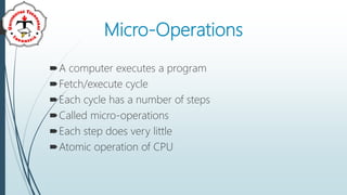
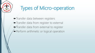
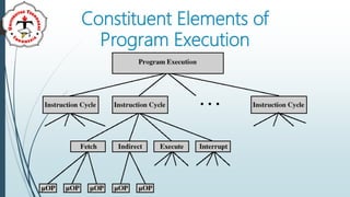
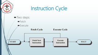
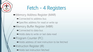
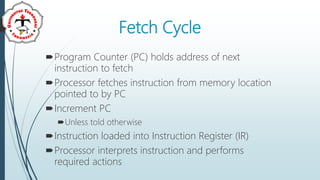
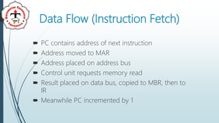
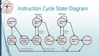
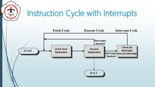
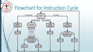
Organisasi dan Arsitektur
Komputer
Ajeng Savitri Puspaningrum, M.Kom
Pertemuan 8
Control Unit (CU) – Part 2
Explaining CU’s micro operation
Explaining how CU’s micro operation
works
Micro-Operations
A computer executes a program
Fetch/execute cycle
Each cycle has a number of steps
Called micro-operations
Each step does very little
Atomic operation of CPU
Types of Micro-operation
Transfer data between registers
Transfer data from register to external
Transfer data from external to register
Perform arithmetic or logical operation
Constituent Elements of
Program Execution
Instruction Cycle
Two steps:
Fetch
Execute
Fetch - 4 Registers
Memory Address Register (MAR)
Connected to address bus
Specifies address for read or write op
Memory Buffer Register (MBR)
Connected to data bus
Holds data to write or last data read
Program Counter (PC)
Holds address of next instruction to be fetched
Instruction Register (IR)
Holds last instruction fetched
Fetch Cycle
Program Counter (PC) holds address of next
instruction to fetch
Processor fetches instruction from memory location
pointed to by PC
Increment PC
Unless told otherwise
Instruction loaded into Instruction Register (IR)
Processor interprets instruction and performs
required actions
Data Flow (Instruction Fetch)
 PC contains address of next instruction
 Address moved to MAR
 Address placed on address bus
 Control unit requests memory read
 Result placed on data bus, copied to MBR, then to
IR
 Meanwhile PC incremented by 1
Data Flow (Data Fetch)
IR is examined
If indirect addressing, indirect cycle is performed
Indirect Cycle
The execution of an
instruction involves an
operand or more in
memory, each of
which requires
memory access
Instruction Cycle State Diagram
Data Flow (Execute)
May take many forms
Depends on instruction being executed
May include
Memory read/write
Input/Output
Register transfers
ALU operations
Data Flow (Interrupt)
Simple
Predictable
Current PC saved to allow resumption after interrupt
Contents of PC copied to MBR
Special memory location (e.g. stack pointer) loaded to
MAR
MBR written to memory
PC loaded with address of interrupt handling routine
Next instruction (first of interrupt handler) can be fetched
Interrupt Cycle
Added to instruction cycle
Processor checks for interrupt : Indicated by an
interrupt signal
If no interrupt, fetch next instruction
If interrupt pending:
 Suspend execution of current program
 Save context
 Set PC to start address of interrupt handler routine
 Process interrupt
 Restore context and continue interrupted program
Instruction Cycle with Interrupts
Flowchart for Instruction Cycle
01 (indirect)
Prefetch
Fetch accessing main memory
Execution usually does not access main memory
Can fetch next instruction during execution of
current instruction
Called instruction prefetch
Refference
Stalling, William, Computer Organization
and Architecture, 10th Edition, Pearson,
2015
Abdurohman, Maman, Organisasi dan
Arsitektur Komputer revisi ke-4, Penerbit
Informatika, 2017
Terima Kasih
ajeng.savitri@teknokrat.ac.id
https://teknokrat.ac.id/en/
https://spada.teknokrat.ac.id/

Control Unit (CU) – Part 2