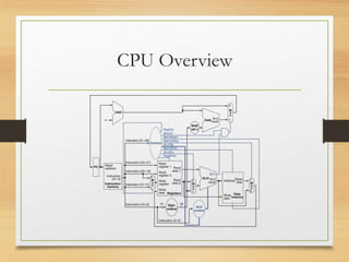
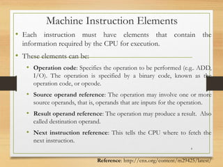
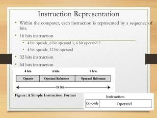
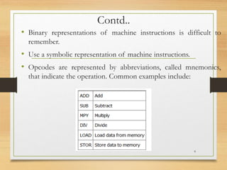
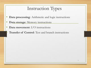
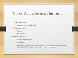
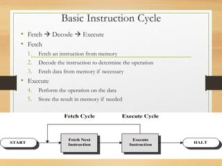
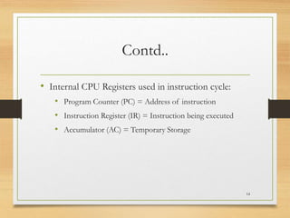
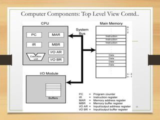
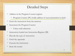
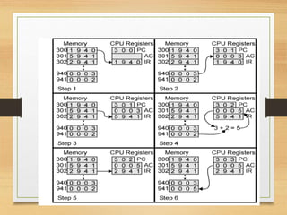
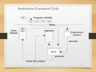
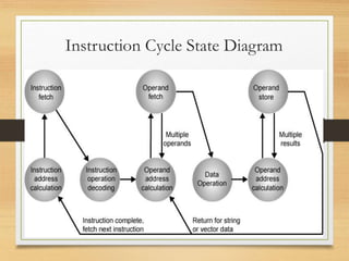
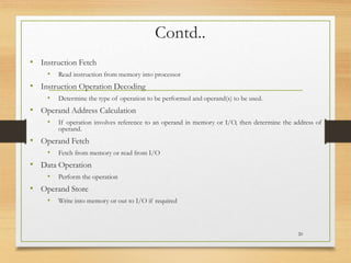
4 – Processor Basics
CPU Overview
Outline
• Basic Operational Concepts
• Processor Clock
• Instruction Representation
• Instruction Cycle
3
Machine Instruction Elements
• Each instruction must have elements that contain the
information required by the CPU for execution.
• These elements can be:
• Operation code: Specifies the operation to be performed (e.g.. ADD,
I/O). The operation is specified by a binary code, known as the
operation code, or opcode.
• Source operand reference: The operation may involve one or more
source operands, that is, operands that are inputs for the operation.
• Result operand reference: The operation may produce a result. Also
called destination operand.
• Next instruction reference: This tells the CPU where to fetch the
next instruction.
4
Reference: http://cnx.org/content/m29425/latest/
Instruction Representation
• Within the computer, each instruction is represented by a sequence of
bits.
• 16 bits instruction
• 4 bit opcode, 6 bit operand 1, 6 bit operand 2
• 4 bit opcode, 12 bit operand
• 32 bits instruction
• 64 bits instruction
5
Figure: A Simple Instruction Format
Contd..
• Binary representations of machine instructions is difficult to
remember.
• Use a symbolic representation of machine instructions.
• Opcodes are represented by abbreviations, called mnemonics,
that indicate the operation. Common examples include:
6
Instruction Types
• Data processing: Arithmetic and logic instructions
• Data storage: Memory instructions
• Data movement: I/O instructions
• Transfer of Control: Test and branch instructions
7
No. of Addresses in an Instruction
• Three addresses
• Operand 1, operand 2, result
• Two addresses
• Source
• Destination
• One addresses
• Source or Destination
• Zero address
• Zero-address instructions are applicable to a special memory organization,
called a Stack. A stack is a last-in-first-out set of locations.
8
Types of Operands
• Machine instructions operate on data.
• The most important general categories of data are:
• Addresses
• Numbers
• Characters
• Logical data
9
Basic Operations – Processor
• Execute the software by fetching instruction from memory
• Look for any external signal and react accordingly
• Input signals from keyboard or mouse etc.
10
Processor Clock
• Heart of any processor
• Simple digital signals at equal time intervals
• Alternate On Off states
• All activity within the CPU is synchronized with the edges (rising
or falling) of this clock signal.
11
Reference: http://www.plantation-
productions.com/Webster/www.artofasm.com/Linux/HTML/SystemOrganizationa4.html
Rising Edge Falling Edge
Program Counter (a.k.a. Binary Counter)
• With every falling edge or rising edge (depending upon processor) of clock
signal, the counter is incremented by one.
• Width varies from processor to processor
• The contents of PC are used as target address for the memory area
12
Microprocessor
Memory
Control Unit
(CU)
PC
Data Buffer
Memory
Read
Memory address
Data from Memory
Data
Address
Read
Figure: Reading from memory
Basic Instruction Cycle
• Fetch  Decode  Execute
• Fetch
1. Fetch an instruction from memory
2. Decode the instruction to determine the operation
3. Fetch data from memory if necessary
• Execute
4. Perform the operation on the data
5. Store the result in memory if needed
13
Contd..
• Internal CPU Registers used in instruction cycle:
• Program Counter (PC) = Address of instruction
• Instruction Register (IR) = Instruction being executed
• Accumulator (AC) = Temporary Storage
14
Computer Components: Top Level View Contd..
15
Detailed Steps
• Address in the Program Counter register
• Program Counter (PC) holds address of next instruction to fetch
• Fetch the instruction from the memory
• Increment the Program Counter
• Unless told otherwise
• Instruction loaded into Instruction Register (IR)
• Decode the type of instruction
• Fetch the operands
• Execute the instruction
• Store the results
16
Example Program Execution
17
Instruction Execution Cycle
18
I-1 I-2 I-3 I-4
PC Program (RAM)
I-1
Instruction
Queue
op1
op2
Data
(RAM)
fetch
ALU
registers
store the output
decode
execute
Instruction Cycle State Diagram
19
Contd..
• Instruction Fetch
• Read instruction from memory into processor
• Instruction Operation Decoding
• Determine the type of operation to be performed and operand(s) to be used.
• Operand Address Calculation
• If operation involves reference to an operand in memory or I/O, then determine the address of
operand.
• Operand Fetch
• Fetch from memory or read from I/O
• Data Operation
• Perform the operation
• Operand Store
• Write into memory or out to I/O if required
20

Lecture004BasicsofthedProcessor (1).pptx

  • 1.
  • 2.
  • 3.
    Outline • Basic OperationalConcepts • Processor Clock • Instruction Representation • Instruction Cycle 3
  • 4.
    Machine Instruction Elements •Each instruction must have elements that contain the information required by the CPU for execution. • These elements can be: • Operation code: Specifies the operation to be performed (e.g.. ADD, I/O). The operation is specified by a binary code, known as the operation code, or opcode. • Source operand reference: The operation may involve one or more source operands, that is, operands that are inputs for the operation. • Result operand reference: The operation may produce a result. Also called destination operand. • Next instruction reference: This tells the CPU where to fetch the next instruction. 4 Reference: http://cnx.org/content/m29425/latest/
  • 5.
    Instruction Representation • Withinthe computer, each instruction is represented by a sequence of bits. • 16 bits instruction • 4 bit opcode, 6 bit operand 1, 6 bit operand 2 • 4 bit opcode, 12 bit operand • 32 bits instruction • 64 bits instruction 5 Figure: A Simple Instruction Format
  • 6.
    Contd.. • Binary representationsof machine instructions is difficult to remember. • Use a symbolic representation of machine instructions. • Opcodes are represented by abbreviations, called mnemonics, that indicate the operation. Common examples include: 6
  • 7.
    Instruction Types • Dataprocessing: Arithmetic and logic instructions • Data storage: Memory instructions • Data movement: I/O instructions • Transfer of Control: Test and branch instructions 7
  • 8.
    No. of Addressesin an Instruction • Three addresses • Operand 1, operand 2, result • Two addresses • Source • Destination • One addresses • Source or Destination • Zero address • Zero-address instructions are applicable to a special memory organization, called a Stack. A stack is a last-in-first-out set of locations. 8
  • 9.
    Types of Operands •Machine instructions operate on data. • The most important general categories of data are: • Addresses • Numbers • Characters • Logical data 9
  • 10.
    Basic Operations –Processor • Execute the software by fetching instruction from memory • Look for any external signal and react accordingly • Input signals from keyboard or mouse etc. 10
  • 11.
    Processor Clock • Heartof any processor • Simple digital signals at equal time intervals • Alternate On Off states • All activity within the CPU is synchronized with the edges (rising or falling) of this clock signal. 11 Reference: http://www.plantation- productions.com/Webster/www.artofasm.com/Linux/HTML/SystemOrganizationa4.html Rising Edge Falling Edge
  • 12.
    Program Counter (a.k.a.Binary Counter) • With every falling edge or rising edge (depending upon processor) of clock signal, the counter is incremented by one. • Width varies from processor to processor • The contents of PC are used as target address for the memory area 12 Microprocessor Memory Control Unit (CU) PC Data Buffer Memory Read Memory address Data from Memory Data Address Read Figure: Reading from memory
  • 13.
    Basic Instruction Cycle •Fetch  Decode  Execute • Fetch 1. Fetch an instruction from memory 2. Decode the instruction to determine the operation 3. Fetch data from memory if necessary • Execute 4. Perform the operation on the data 5. Store the result in memory if needed 13
  • 14.
    Contd.. • Internal CPURegisters used in instruction cycle: • Program Counter (PC) = Address of instruction • Instruction Register (IR) = Instruction being executed • Accumulator (AC) = Temporary Storage 14
  • 15.
    Computer Components: TopLevel View Contd.. 15
  • 16.
    Detailed Steps • Addressin the Program Counter register • Program Counter (PC) holds address of next instruction to fetch • Fetch the instruction from the memory • Increment the Program Counter • Unless told otherwise • Instruction loaded into Instruction Register (IR) • Decode the type of instruction • Fetch the operands • Execute the instruction • Store the results 16
  • 17.
  • 18.
    Instruction Execution Cycle 18 I-1I-2 I-3 I-4 PC Program (RAM) I-1 Instruction Queue op1 op2 Data (RAM) fetch ALU registers store the output decode execute
  • 19.
  • 20.
    Contd.. • Instruction Fetch •Read instruction from memory into processor • Instruction Operation Decoding • Determine the type of operation to be performed and operand(s) to be used. • Operand Address Calculation • If operation involves reference to an operand in memory or I/O, then determine the address of operand. • Operand Fetch • Fetch from memory or read from I/O • Data Operation • Perform the operation • Operand Store • Write into memory or out to I/O if required 20