Download to read offline


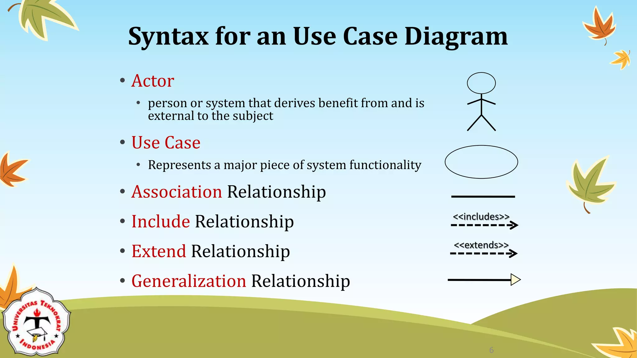


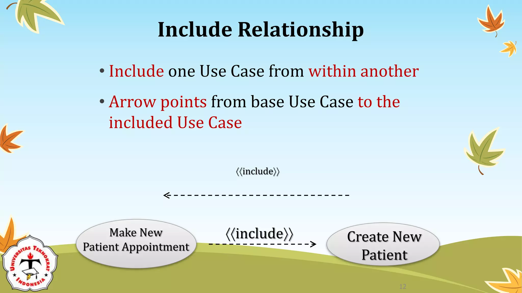


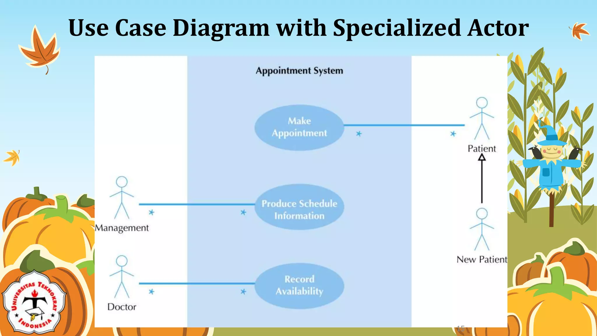


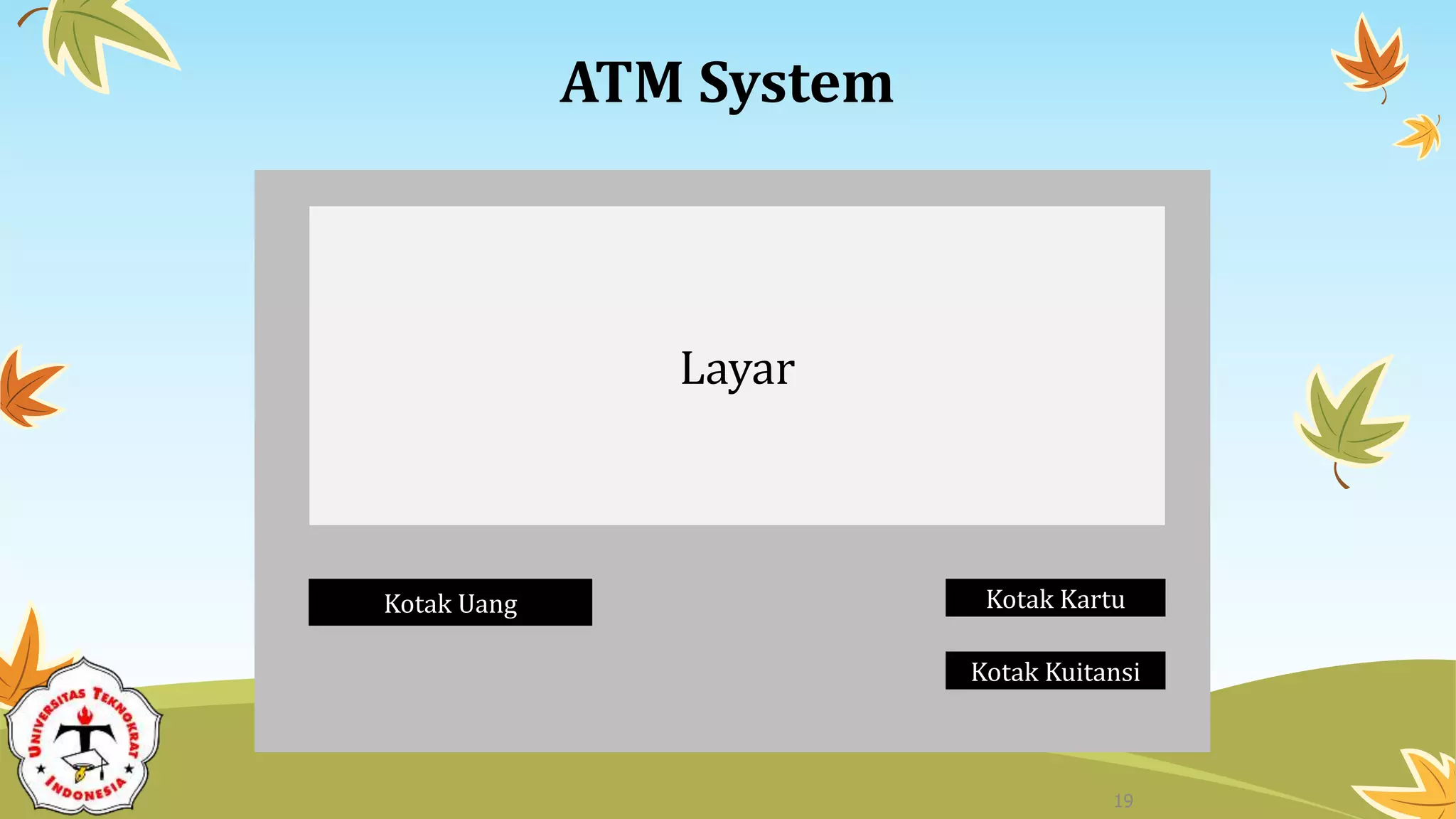


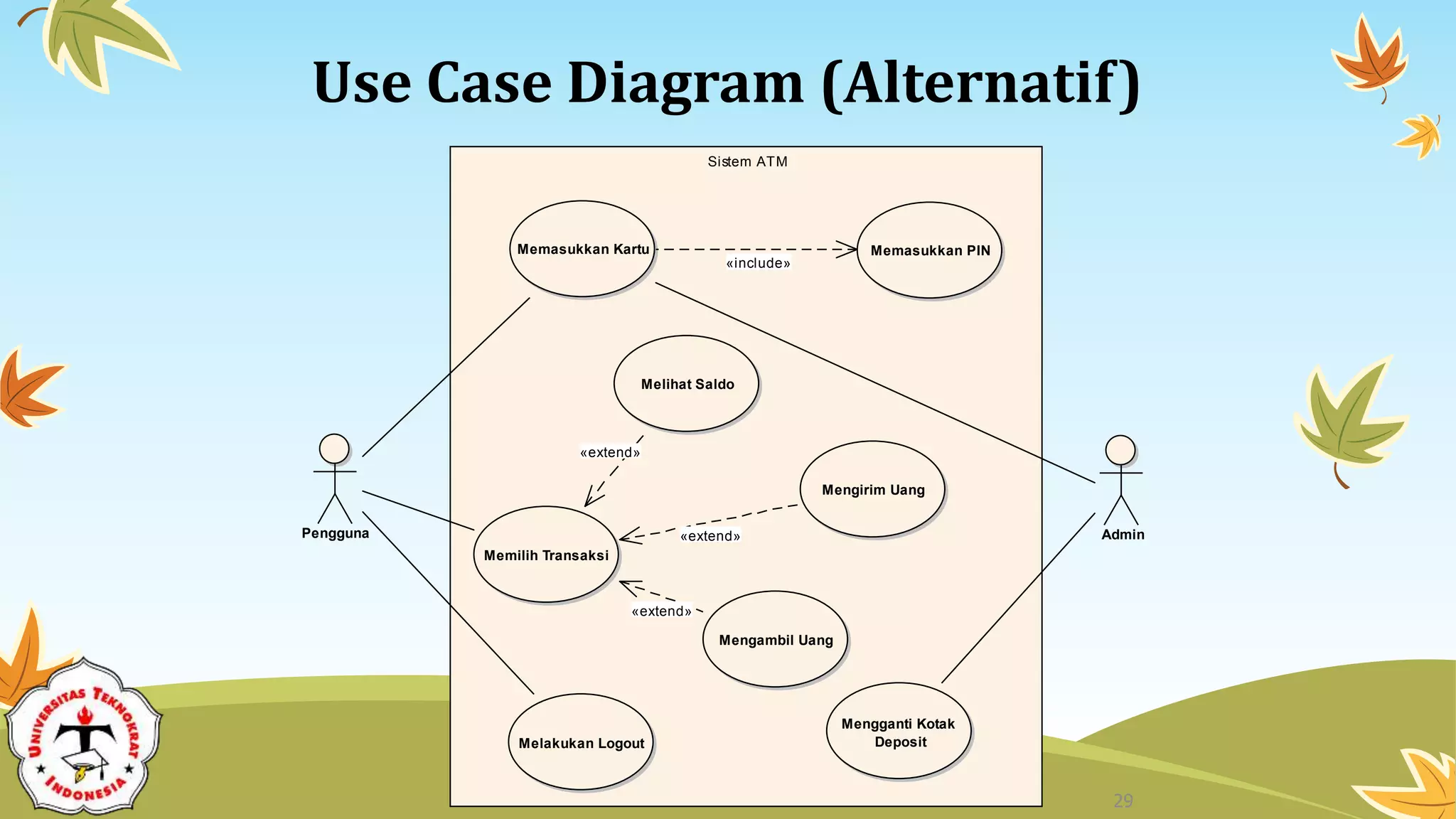


The document discusses use case diagrams for systems analysis and design. It provides examples of use case diagrams for an appointment system and an ATM system. Key elements of use case diagrams are described, including actors, use cases, relationships like generalization, include and extend, and the system boundary. The ATM system example demonstrates how a use case diagram can model the interactions between an actor (user) and the various functions of an ATM machine like checking balance, transferring money, withdrawing money and logging out.