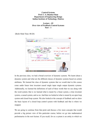
- The document provides an overview of feedback control systems and key concepts related to their design and analysis.
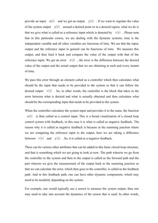
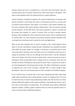
- It discusses the basic components of a closed-loop control system including a controller, plant/system, reference input, error calculation, and feedback loop. It also describes how sensor dynamics, actuator dynamics, and disturbances can impact the design.
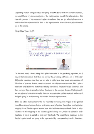
- Two common mathematical representations - transfer function and state-space - are introduced. Stability and performance are identified as the two critical aspects to consider when designing a controller.