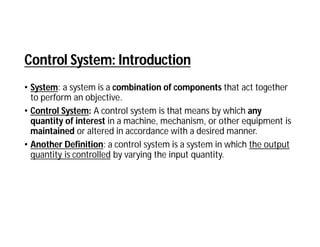
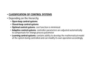
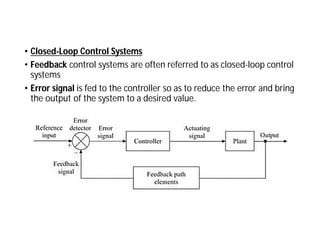
Control System
Control System: Introduction
• System: a system is a combination of components that act together
to perform an objective.
• Control System: A control system is that means by which any
quantity of interest in a machine, mechanism, or other equipment is
maintained or altered in accordance with a desired manner.
• Another Definition: a control system is a system in which the output
quantity is controlled by varying the input quantity.
Control System: Introduction
• Physical Model: A physical model is a representation of the
underlying hardware elements of a distributed system that abstracts
away from specific details within them.
• Mathematical Model: A mathematical model is the mathematical
representation of the physical model, through use of appropriate
physical laws.
• CLASSIFICATION OF CONTROL SYSTEMS
• Depending on the hierarchy
• Open-loop control systems
• Closed-loop control systems
• Optimal control systems: cost function is minimized
• Adaptive control systems: controller parameters are adjusted automatically
to compensate for change process parameter
• Learning control systems: contains ability to develop the mathematical model
of the system being controlled and can modify its own operation accordingly.
• CLASSIFICATION OF CONTROL SYSTEMS
• Depending on the presence of human
• Manually controlled systems: needs an external effort to adjust and correct
the errors
• Automatic control systems: needs no external effort
• CLASSIFICATION OF CONTROL SYSTEMS
• Depending on presence of feedback
• Open-loop control system
• Closed-loop control systems or feedback control systems
• CLASSIFICATION OF CONTROL SYSTEMS
• According to the purpose of the system
• Position control systems: output is the desired angular position of the DC
motor
• Velocity control systems: it enables the system to respond to changing
velocity commands
• Process control systems: Process control system monitors and adjust a
process to give a desired output
• Temperature control systems: To maintain a device at a constant
temperature
• Traffic control systems, etc.
• According to the method of analysis and
• linear control systems and
• nonlinear control systems
• Depending on whether the parameters of I he system remain
constant or vary with time
• Time-varying control systems
• Time invariant control systems
• According to the types of signals used in the system
• Continuous data control systems
• discrete-data control systems
• Depending on the number of inputs and outputs
• single-input-single-output (SISO) control systems
• multi-input-multi-output (MIMO) control systems / multi-variable systems
• Depending on the number of open-loop poles of the system transfer
function present at the origin of the s-plane
• Type-0
• Type-1
• Type-2 etc.
• Depending on the order of the differential equation used to describe
the system
• first-order control systems
• second-order control systems etc.
• Depending on the type of damping
• Undamped systems
• Underdamped systems
• Critically damped systems
• Over-damped systems
• Open-Loop Control Systems
• Definition: Those systems in which the output has no effect on input
are called open-loop control systems
• can be used when the relationship between the input and the
output is known
• Example-Washing Machine-soaking, washing and rinsing in the
washer operate on a time basis
• Example- Traffic Light Control System -that operates by means of
signals on a time basis
• Block Diagram of an Open-loop System
• Advantages of Open Loop Control System
• Open Loop Control Systems are very simple and easy to design.
• These are considerably cheaper than other types of control
systems.
• Maintenance of an open loop control system is very simple.
• These types of systems are easy to construct and are convenient
to use.
• Disadvantages of Open Loop control System
• The bandwidth of open loop control system is less.
• The non-feedback system doesn’t facilitate the process of
automation.
• Open loop systems are inaccurate in nature and also unreliable.
• If their output is affected by some external disturbances, there is
no way to correct them automatically as these are non-feedback
systems.
• Closed-Loop Control Systems
• Feedback control systems are often referred to as closed-loop control
systems
• Error signal is fed to the controller so as to reduce the error and bring
the output of the system to a desired value.
• Closed-Loop Control Systems
• Example: room temperature control system
• Advantages
• Highly accurate as any error arising is corrected due to the presence
of a feedback signal.
• The bandwidth range is large.
• Facilitates automation.
• Disadvantages of Closed Loop Control System
• They are costlier.
• They are complicated to design.
• They consume more power.
• Required more maintenance.
• Feedback leads to an oscillatory response.
• Overall gain is reduced due to the presence of feedback.
• What is Feedback
The input-output relation of a single loop control system
• Effect of Feedback on Overall Gain
• feedback affects the gain of a system by a factor 1/(1 -+ GH )
• G and H are functions of frequency: feedback could increase the
system gain in one frequency range but decrease it in another
• Effect of Feedback on Stability
• If GH = -1: the output of the system is infinite; system is said to be
unstable.
• GH =-1, is not the only condition for unstability
• SERVOMECHANISM
• About feedback control systems in which the controlled variable is
mechanical position or time derivatives of position(velocity and
acceleration)
• Automatic Tank Level Control System
• The purpose of this system is to maintain the liquid level h (output ) in
the tank as close to the desired liquid level H as possible, even when
the output flow rate is varied by opening the valve V1.
• done by controlling the opening of the valve V2
• potentiometer acts as an error detector
• Slider arm A is positioned corresponding to the desired liquid level H
• The power amplifier and the motor drive form the control elements
• float forms a feedback path element
• Working
• The liquid level is sensed by a float and it positions the slider arm B
(in the potentiometer)
• potentiometer gives an error voltage proportional to the change in
liquid level
• The error voltage actuates the motor through a power amplifier
• The output of motor drive decreases or increases the opening of the
valve V2
• A Position Control System (DC Closed-Loop Control System)
• servosystem used to position a load shaft
• driving motor is geared to the load to be moved
• The potentiometer is used us the error detector
• The output and desired position are θC and θR
• These positions are compared by the potentiometer whose output voltage
VE is proportional to the error in angular position θE= θR - θC .
• The voltage VE is used to control the field current of a dc generator, which
supplies armature voltage to the driving motor.
• AC Closed-Loop Control System
• The output signal θy representing the load position is applied to the
synchro control transformer
• A synchro control transformer is used in conjunction with a synchro
transmitter to act as error sensor of mechanical components
• The reference input θr representing the desired output is applied to
the synchro transmitter
• The error signal is amplified by an ac amplifier and drives the ac
servomotor which in turn positions the load through the gear box
• Mathematical Models of Physical Systems
• Modelling of Mechanical System Elements
• The motion of mechanical elements can be described in various
dimensions as
• Translational,
• Rotational, or
• Combination of both
• Translational systems are those in which the motion takes place
along a straight line

Notes 1.pdf

  • 1.
  • 2.
    Control System: Introduction •System: a system is a combination of components that act together to perform an objective. • Control System: A control system is that means by which any quantity of interest in a machine, mechanism, or other equipment is maintained or altered in accordance with a desired manner. • Another Definition: a control system is a system in which the output quantity is controlled by varying the input quantity.
  • 3.
    Control System: Introduction •Physical Model: A physical model is a representation of the underlying hardware elements of a distributed system that abstracts away from specific details within them. • Mathematical Model: A mathematical model is the mathematical representation of the physical model, through use of appropriate physical laws.
  • 4.
    • CLASSIFICATION OFCONTROL SYSTEMS • Depending on the hierarchy • Open-loop control systems • Closed-loop control systems • Optimal control systems: cost function is minimized • Adaptive control systems: controller parameters are adjusted automatically to compensate for change process parameter • Learning control systems: contains ability to develop the mathematical model of the system being controlled and can modify its own operation accordingly.
  • 5.
    • CLASSIFICATION OFCONTROL SYSTEMS • Depending on the presence of human • Manually controlled systems: needs an external effort to adjust and correct the errors • Automatic control systems: needs no external effort
  • 6.
    • CLASSIFICATION OFCONTROL SYSTEMS • Depending on presence of feedback • Open-loop control system • Closed-loop control systems or feedback control systems
  • 7.
    • CLASSIFICATION OFCONTROL SYSTEMS • According to the purpose of the system • Position control systems: output is the desired angular position of the DC motor • Velocity control systems: it enables the system to respond to changing velocity commands • Process control systems: Process control system monitors and adjust a process to give a desired output • Temperature control systems: To maintain a device at a constant temperature • Traffic control systems, etc.
  • 8.
    • According tothe method of analysis and • linear control systems and • nonlinear control systems • Depending on whether the parameters of I he system remain constant or vary with time • Time-varying control systems • Time invariant control systems • According to the types of signals used in the system • Continuous data control systems • discrete-data control systems
  • 9.
    • Depending onthe number of inputs and outputs • single-input-single-output (SISO) control systems • multi-input-multi-output (MIMO) control systems / multi-variable systems • Depending on the number of open-loop poles of the system transfer function present at the origin of the s-plane • Type-0 • Type-1 • Type-2 etc. • Depending on the order of the differential equation used to describe the system • first-order control systems • second-order control systems etc.
  • 10.
    • Depending onthe type of damping • Undamped systems • Underdamped systems • Critically damped systems • Over-damped systems
  • 11.
    • Open-Loop ControlSystems • Definition: Those systems in which the output has no effect on input are called open-loop control systems • can be used when the relationship between the input and the output is known • Example-Washing Machine-soaking, washing and rinsing in the washer operate on a time basis • Example- Traffic Light Control System -that operates by means of signals on a time basis
  • 12.
    • Block Diagramof an Open-loop System
  • 13.
    • Advantages ofOpen Loop Control System • Open Loop Control Systems are very simple and easy to design. • These are considerably cheaper than other types of control systems. • Maintenance of an open loop control system is very simple. • These types of systems are easy to construct and are convenient to use.
  • 14.
    • Disadvantages ofOpen Loop control System • The bandwidth of open loop control system is less. • The non-feedback system doesn’t facilitate the process of automation. • Open loop systems are inaccurate in nature and also unreliable. • If their output is affected by some external disturbances, there is no way to correct them automatically as these are non-feedback systems.
  • 15.
    • Closed-Loop ControlSystems • Feedback control systems are often referred to as closed-loop control systems • Error signal is fed to the controller so as to reduce the error and bring the output of the system to a desired value.
  • 16.
    • Closed-Loop ControlSystems • Example: room temperature control system • Advantages • Highly accurate as any error arising is corrected due to the presence of a feedback signal. • The bandwidth range is large. • Facilitates automation.
  • 17.
    • Disadvantages ofClosed Loop Control System • They are costlier. • They are complicated to design. • They consume more power. • Required more maintenance. • Feedback leads to an oscillatory response. • Overall gain is reduced due to the presence of feedback.
  • 18.
    • What isFeedback The input-output relation of a single loop control system
  • 19.
    • Effect ofFeedback on Overall Gain • feedback affects the gain of a system by a factor 1/(1 -+ GH ) • G and H are functions of frequency: feedback could increase the system gain in one frequency range but decrease it in another • Effect of Feedback on Stability • If GH = -1: the output of the system is infinite; system is said to be unstable. • GH =-1, is not the only condition for unstability
  • 20.
    • SERVOMECHANISM • Aboutfeedback control systems in which the controlled variable is mechanical position or time derivatives of position(velocity and acceleration)
  • 21.
    • Automatic TankLevel Control System • The purpose of this system is to maintain the liquid level h (output ) in the tank as close to the desired liquid level H as possible, even when the output flow rate is varied by opening the valve V1. • done by controlling the opening of the valve V2 • potentiometer acts as an error detector • Slider arm A is positioned corresponding to the desired liquid level H • The power amplifier and the motor drive form the control elements • float forms a feedback path element
  • 23.
    • Working • Theliquid level is sensed by a float and it positions the slider arm B (in the potentiometer) • potentiometer gives an error voltage proportional to the change in liquid level • The error voltage actuates the motor through a power amplifier • The output of motor drive decreases or increases the opening of the valve V2
  • 24.
    • A PositionControl System (DC Closed-Loop Control System) • servosystem used to position a load shaft • driving motor is geared to the load to be moved • The potentiometer is used us the error detector • The output and desired position are θC and θR • These positions are compared by the potentiometer whose output voltage VE is proportional to the error in angular position θE= θR - θC . • The voltage VE is used to control the field current of a dc generator, which supplies armature voltage to the driving motor.
  • 26.
    • AC Closed-LoopControl System • The output signal θy representing the load position is applied to the synchro control transformer • A synchro control transformer is used in conjunction with a synchro transmitter to act as error sensor of mechanical components • The reference input θr representing the desired output is applied to the synchro transmitter • The error signal is amplified by an ac amplifier and drives the ac servomotor which in turn positions the load through the gear box
  • 28.
    • Mathematical Modelsof Physical Systems • Modelling of Mechanical System Elements • The motion of mechanical elements can be described in various dimensions as • Translational, • Rotational, or • Combination of both • Translational systems are those in which the motion takes place along a straight line