Download to read offline

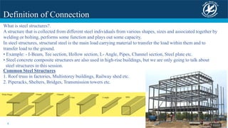


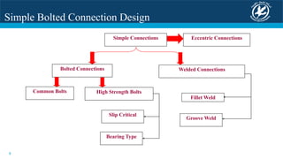


Structural connection design and constructability are discussed. Connections are critical for transferring forces between structural members safely and economically. Simple bolted connections are commonly used due to ease of fabrication and ability to accommodate site adjustments. Connection types include shear, moment, and splice connections. Failure modes like bolt shear, bearing, and block shear are reviewed. Constructability considerations include connection design for simplicity and repetition to reduce erection costs.


