Steel Structures
Lecture 23-Design of Connections
[Spring 2021]
Engr. Danish Saeed
Lecturer
Department of Civil Engineering
KFUEIT, RYK
1
2.
Shear Strength ofConnections
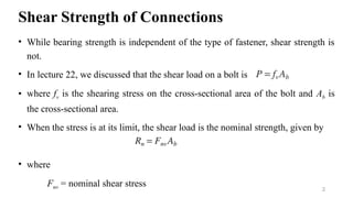
• While bearing strength is independent of the type of fastener, shear strength is
not.
• In lecture 22, we discussed that the shear load on a bolt is
• where fv is the shearing stress on the cross-sectional area of the bolt and Ab is
the cross-sectional area.
• When the stress is at its limit, the shear load is the nominal strength, given by
• where
Fnv = nominal shear stress 2
3.
Shear Strength ofConnections
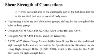
Ab = cross-sectional area of the unthreaded part of the bolt (also known
as the nominal bolt area or nominal body area)
• High-strength bolts are available in two groups, defined by the strength of the
bolts in those groups.
• Group A: ASTM A325, F1852, A352, A354 Grade BC, and A449.
• Group B: ASTM A490, F2280, and A354 Grade BD.
• ASTM A325 (from Group A) and A490 (from Group B) are the traditional
high strength bolts and are covered in the Specification for Structural Joints
Using High Strength Bolts (RCSC, 2009), which is the basis for the AISC
provisions for high-strength bolts. 3
4.
Shear Strength ofConnections
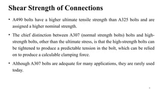
• A490 bolts have a higher ultimate tensile strength than A325 bolts and are
assigned a higher nominal strength.
• The chief distinction between A307 (normal strength bolts) bolts and high-
strength bolts, other than the ultimate stress, is that the high-strength bolts can
be tightened to produce a predictable tension in the bolt, which can be relied
on to produce a calculable clamping force.
• Although A307 bolts are adequate for many applications, they are rarely used
today.
4
5.
Shear Strength ofConnections
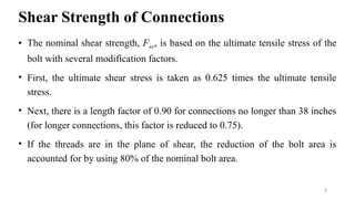
• The nominal shear strength, Fnv, is based on the ultimate tensile stress of the
bolt with several modification factors.
• First, the ultimate shear stress is taken as 0.625 times the ultimate tensile
stress.
• Next, there is a length factor of 0.90 for connections no longer than 38 inches
(for longer connections, this factor is reduced to 0.75).
• If the threads are in the plane of shear, the reduction of the bolt area is
accounted for by using 80% of the nominal bolt area.
5
6.
Shear Strength ofConnections
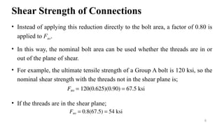
• Instead of applying this reduction directly to the bolt area, a factor of 0.80 is
applied to Fnv.
• In this way, the nominal bolt area can be used whether the threads are in or
out of the plane of shear.
• For example, the ultimate tensile strength of a Group A bolt is 120 ksi, so the
nominal shear strength with the threads not in the shear plane is;
• If the threads are in the shear plane;
6
7.
Shear Strength ofConnections
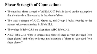
• The nominal shear strength of ASTM A307 bolts is based on the assumption
that the threads will always be in the plane of shear.
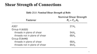
• The shear strengths of A307, Group A, and Group B bolts, rounded to the
nearest ksi, are summarized in Table 23.1.
• The values in Table 23.1 are taken from AISC Table J3.2.
• AISC Table J3.2 refers to threads in a plane of shear as “not excluded from
shear planes” and refers to threads not in a plane of shear as “excluded from
shear planes.”
7
Shear Strength ofConnections
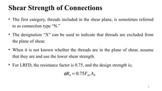
• The first category, threads included in the shear plane, is sometimes referred
to as connection type “N.”
• The designation “X” can be used to indicate that threads are excluded from
the plane of shear.
• When it is not known whether the threads are in the plane of shear, assume
that they are and use the lower shear strength.
• For LRFD, the resistance factor is 0.75, and the design strength is;
9
10.
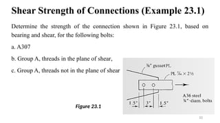
Shear Strength ofConnections (Example 23.1)
Determine the strength of the connection shown in Figure 23.1, based on
bearing and shear, for the following bolts:
a. A307
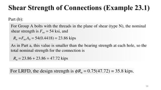
b. Group A, threads in the plane of shear,
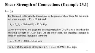
c. Group A, threads not in the plane of shear
10
Figure 23.1
11.
Shear Strength ofConnections (Example 23.1)
Solution: The connection can be classified as a simple connection, and each
fastener can be considered to resist an equal share of the load. Because the
bearing strength will be the same for parts a, b, and c, it will be calculated first.
11
12.
Shear Strength ofConnections (Example 23.1)
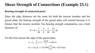
Bearing strength of connected parts:
Since the edge distances are the same for both the tension member and the
gusset plate, the bearing strength of the gusset plate will control because it is
thinner than the tension member. For bearing strength computation, use a hole
diameter of;
For the hole nearest the edge of the gusset plate,
12
13.
Shear Strength ofConnections (Example 23.1)
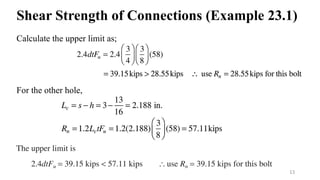
Calculate the upper limit as;
For the other hole,
13
14.
Shear Strength ofConnections (Example 23.1)
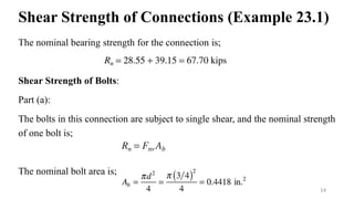
The nominal bearing strength for the connection is;
Shear Strength of Bolts:
Part (a):
The bolts in this connection are subject to single shear, and the nominal strength
of one bolt is;
The nominal bolt area is;
14
15.
Shear Strength ofConnections (Example 23.1)
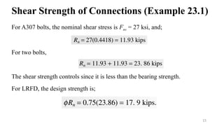
For A307 bolts, the nominal shear stress is Fnv = 27 ksi, and;
For two bolts,
The shear strength controls since it is less than the bearing strength.
For LRFD, the design strength is;
15
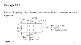
Example 23.2
Check boltspacing, edge distances, and bearing for the connection shown in
Figure 23.2.
18
Figure 23.2
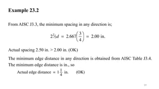
19.
Example 23.2
From AISCJ3.3, the minimum spacing in any direction is;
Actual spacing 2.50 in. > 2.00 in. (OK)
The minimum edge distance in any direction is obtained from AISC Table J3.4.
The minimum edge distance is in., so
19
20.
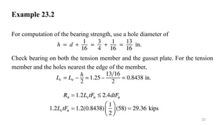
Example 23.2
For computationof the bearing strength, use a hole diameter of
Check bearing on both the tension member and the gusset plate. For the tension
member and the holes nearest the edge of the member,
20
21.
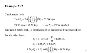
Example 23.2
Check upperlimit:
This result means that lc is small enough so that it must be accounted for.
For the other holes,
21
22.
Example 23.2
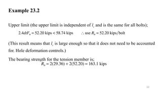
Upper limit(the upper limit is independent of lc and is the same for all bolts);
(This result means that lc is large enough so that it does not need to be accounted
for. Hole deformation controls.)
The bearing strength for the tension member is;
22
23.
Example 23.2
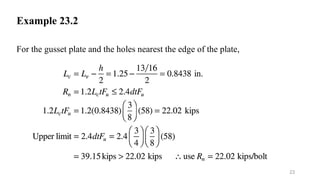
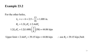
For thegusset plate and the holes nearest the edge of the plate,
23
Example 23.2
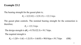
The bearingstrength for the gusset plate is;
The gusset plate controls. The nominal bearing strength for the connection is
therefore;
25
26.
Example 23.2
The boltspacing and edge distances in Example 22.1 are the same for both the
tension member and the gusset plate. In addition, the same material is used. Only
the thicknesses are different, so the gusset plate will control. In cases such as this
one, only the thinner component need be checked. If there is a combination of
differences, such as different thicknesses, edge distances, and grades of steel,
both the tension member and the gusset plate should be checked.
26
27.
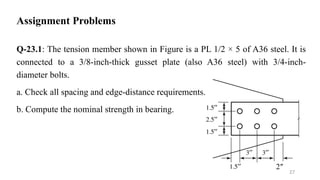
Assignment Problems
Q-23.1: Thetension member shown in Figure is a PL 1/2 × 5 of A36 steel. It is
connected to a 3/8-inch-thick gusset plate (also A36 steel) with 3/4-inch-
diameter bolts.
a. Check all spacing and edge-distance requirements.
b. Compute the nominal strength in bearing.
27
2″
28.
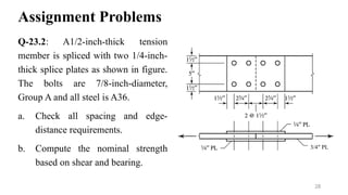
Assignment Problems
Q-23.2: A1/2-inch-thicktension
member is spliced with two 1/4-inch-
thick splice plates as shown in figure.
The bolts are 7/8-inch-diameter,
Group A and all steel is A36.
a. Check all spacing and edge-
distance requirements.
b. Compute the nominal strength
based on shear and bearing.
28
3/4″ PL
![Steel Structures
Lecture 23- Design of Connections
[Spring 2021]
Engr. Danish Saeed
Lecturer
Department of Civil Engineering
KFUEIT, RYK
1](https://image.slidesharecdn.com/steelstructures-lecture23-251208080243-396adb89/85/Steel-Structures-Lecture-23-pptx-Important-1-320.jpg)
![Steel Structures
Lecture 23- Design of Connections
[Spring 2021]
Engr. Danish Saeed
Lecturer
Department of Civil Engineering
KFUEIT, RYK
1](https://image.slidesharecdn.com/steelstructures-lecture23-251208080243-396adb89/75/Steel-Structures-Lecture-23-pptx-Important-1-2048.jpg)