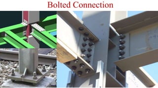
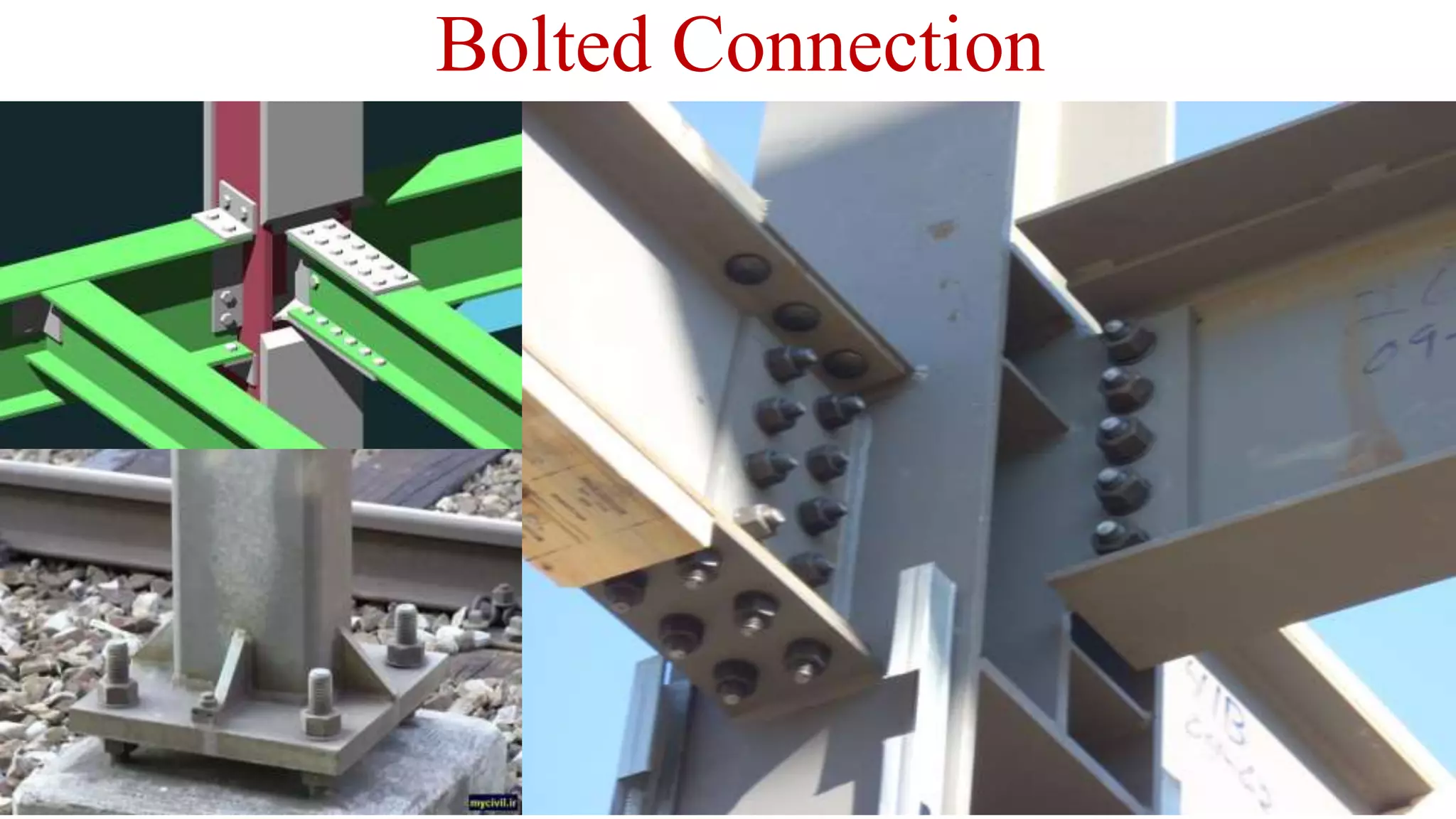
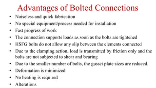
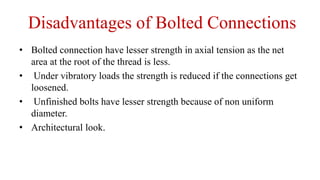
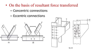
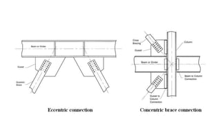
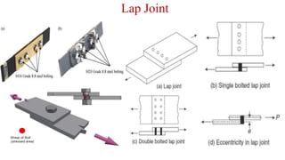
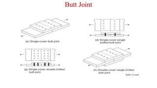
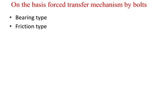
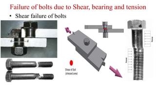
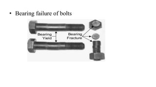
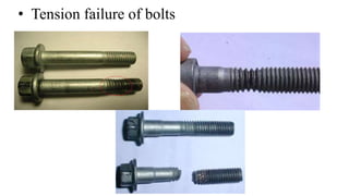
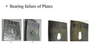
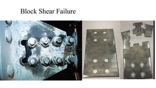
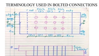
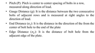
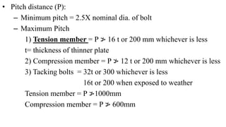
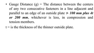
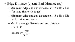
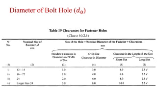
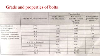
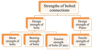
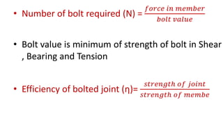
Bolted Connection
Advantages of Bolted Connections
• Noiseless and quick fabrication
• No special equipment/process needed for installation
• Fast progress of work
• The connection supports loads as soon as the bolts are tightened
• HSFG bolts do not allow any slip between the elements connected
• Due to the clamping action, load is transmitted by friction only and the
bolts are not subjected to shear and bearing
• Due to the smaller number of bolts, the gusset plate sizes are reduced.
• Deformation is minimized
• No heating is required
• Alterations
Disadvantages of Bolted Connections
• Bolted connection have lesser strength in axial tension as the net
area at the root of the thread is less.
• Under vibratory loads the strength is reduced if the connections get
loosened.
• Unfinished bolts have lesser strength because of non uniform
diameter.
• Architectural look.
Classification of bolted connection
• On the basis of resultant force transferred
• On the basis of type of force experienced by
bolts
• On the basis forced transfer mechanism by
bolts
• On the basis of resultant force transferred
– Concentric connections
– Eccentric connections
On the basis of type of force experienced by
bolts
• Lap Joint
• Butt Joint
• Bolts in pure tension
• Bolts with tension and shear
Shear Force
Lap Joint
Butt Joint
On the basis forced transfer mechanism by bolts
• Bearing type
• Friction type
Types of bolts
• Bearing Type of bolts
– Unfinished bolts
– Finished bolts
• High strength Friction grip bolts
Unfinished bolts
Finished bolts
• High strength Friction grip bolts
Failure of Bolted connections
• Failure of bolts due to Shear, bearing and
tension
• Failure of connection plates due to bearing,
tearing or block shear failure
Failure of bolts due to Shear, bearing and tension
• Shear failure of bolts
• Bearing failure of bolts
• Tension failure of bolts
• Bearing failure of Plates
Block Shear Failure
TERMINOLOGY USED IN BOLTED CONNECTIONS
• Pitch (P): Pitch is center to center spacing of bolts in a row,
measured along direction of load.
• Gauge Distance (g): It is the distance between the two consecutive
bolts of adjacent rows and is measured at right angles to the
direction of load.
• End Distance (𝑒1): It is the distance in the direction of the from the
center of bolt hole to the end of the plate
• Edge Distance (𝑒2): It is the distance of bolt hole from the
adjacent edge of the plate.
• Pitch distance (P):
– Minimum pitch = 2.5X nominal dia. of bolt
– Maximum Pitch
1) Tension member = P ≯ 16 t or 200 mm whichever is less
t= thickness of thinner plate
2) Compression member = P ≯ 12 t or 200 mm whichever is less
3) Tacking bolts = 32t or 300 whichever is less
16t or 200 when exposed to weather
Tension member = P ≯1000mm
Compression member = P ≯ 600mm
• Gauge Distance (g) = The distance between the centers
of any two consecutive fasteners in a line adjacent and
parallel to an edge of an outside plate ≯ 100 mm plus 4t
or 200 mm, whichever is less, in compression and
tension members.
t = is the thickness of the thinner outside plate.
• Edge Distance (𝑒1)and End Distance (𝑒2)
– Minimum edge and end distance ≮ 1.7 x Hole Dia
(for hand flame cut edges)
– Minimum edge and end distance ≮ 1.5 x Hole Dia
(Rolled steel sections)
– Maximum edge distance and end distance
e≯ 12.t.Ԑ
Where Ԑ=
250
𝑓𝑦
Diameter of Bolt Hole (𝑑0)
Grade and properties of bolts
Strengths of bolted
connections
Design
strength of
bolts
Shear
strength of
bolts
Bearing
strength
of bolts
Tension
strength
of bolts (If any)
Design
strength of
Plates
Tensile
strength of
plate
• Number of bolt required (N) =
𝑓𝑜𝑟𝑐𝑒 𝑖𝑛 𝑚𝑒𝑚𝑏𝑒𝑟
𝑏𝑜𝑙𝑡 𝑣𝑎𝑙𝑢𝑒
• Bolt value is minimum of strength of bolt in Shear
, Bearing and Tension
• Efficiency of bolted joint (ƞ)=
𝑠𝑡𝑟𝑒𝑛𝑔𝑡ℎ 𝑜𝑓 𝑗𝑜𝑖𝑛𝑡
𝑠𝑡𝑟𝑒𝑛𝑔𝑡ℎ 𝑜𝑓 𝑚𝑒𝑚𝑏𝑒

bolted connections.pptx

  • 1.
  • 2.
    Advantages of BoltedConnections • Noiseless and quick fabrication • No special equipment/process needed for installation • Fast progress of work • The connection supports loads as soon as the bolts are tightened • HSFG bolts do not allow any slip between the elements connected • Due to the clamping action, load is transmitted by friction only and the bolts are not subjected to shear and bearing • Due to the smaller number of bolts, the gusset plate sizes are reduced. • Deformation is minimized • No heating is required • Alterations
  • 3.
    Disadvantages of BoltedConnections • Bolted connection have lesser strength in axial tension as the net area at the root of the thread is less. • Under vibratory loads the strength is reduced if the connections get loosened. • Unfinished bolts have lesser strength because of non uniform diameter. • Architectural look.
  • 4.
    Classification of boltedconnection • On the basis of resultant force transferred • On the basis of type of force experienced by bolts • On the basis forced transfer mechanism by bolts
  • 5.
    • On thebasis of resultant force transferred – Concentric connections – Eccentric connections
  • 7.
    On the basisof type of force experienced by bolts • Lap Joint • Butt Joint • Bolts in pure tension • Bolts with tension and shear Shear Force
  • 8.
  • 9.
  • 10.
    On the basisforced transfer mechanism by bolts • Bearing type • Friction type
  • 11.
    Types of bolts •Bearing Type of bolts – Unfinished bolts – Finished bolts • High strength Friction grip bolts
  • 12.
    Unfinished bolts Finished bolts •High strength Friction grip bolts
  • 13.
    Failure of Boltedconnections • Failure of bolts due to Shear, bearing and tension • Failure of connection plates due to bearing, tearing or block shear failure
  • 14.
    Failure of boltsdue to Shear, bearing and tension • Shear failure of bolts
  • 15.
  • 16.
  • 17.
  • 18.
  • 19.
    TERMINOLOGY USED INBOLTED CONNECTIONS
  • 20.
    • Pitch (P):Pitch is center to center spacing of bolts in a row, measured along direction of load. • Gauge Distance (g): It is the distance between the two consecutive bolts of adjacent rows and is measured at right angles to the direction of load. • End Distance (𝑒1): It is the distance in the direction of the from the center of bolt hole to the end of the plate • Edge Distance (𝑒2): It is the distance of bolt hole from the adjacent edge of the plate.
  • 21.
    • Pitch distance(P): – Minimum pitch = 2.5X nominal dia. of bolt – Maximum Pitch 1) Tension member = P ≯ 16 t or 200 mm whichever is less t= thickness of thinner plate 2) Compression member = P ≯ 12 t or 200 mm whichever is less 3) Tacking bolts = 32t or 300 whichever is less 16t or 200 when exposed to weather Tension member = P ≯1000mm Compression member = P ≯ 600mm
  • 22.
    • Gauge Distance(g) = The distance between the centers of any two consecutive fasteners in a line adjacent and parallel to an edge of an outside plate ≯ 100 mm plus 4t or 200 mm, whichever is less, in compression and tension members. t = is the thickness of the thinner outside plate.
  • 23.
    • Edge Distance(𝑒1)and End Distance (𝑒2) – Minimum edge and end distance ≮ 1.7 x Hole Dia (for hand flame cut edges) – Minimum edge and end distance ≮ 1.5 x Hole Dia (Rolled steel sections) – Maximum edge distance and end distance e≯ 12.t.Ԑ Where Ԑ= 250 𝑓𝑦
  • 24.
    Diameter of BoltHole (𝑑0)
  • 25.
  • 26.
    Strengths of bolted connections Design strengthof bolts Shear strength of bolts Bearing strength of bolts Tension strength of bolts (If any) Design strength of Plates Tensile strength of plate
  • 27.
    • Number ofbolt required (N) = 𝑓𝑜𝑟𝑐𝑒 𝑖𝑛 𝑚𝑒𝑚𝑏𝑒𝑟 𝑏𝑜𝑙𝑡 𝑣𝑎𝑙𝑢𝑒 • Bolt value is minimum of strength of bolt in Shear , Bearing and Tension • Efficiency of bolted joint (ƞ)= 𝑠𝑡𝑟𝑒𝑛𝑔𝑡ℎ 𝑜𝑓 𝑗𝑜𝑖𝑛𝑡 𝑠𝑡𝑟𝑒𝑛𝑔𝑡ℎ 𝑜𝑓 𝑚𝑒𝑚𝑏𝑒