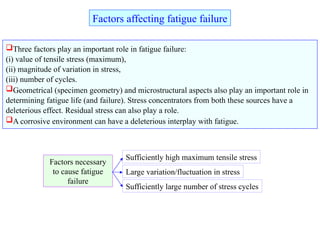
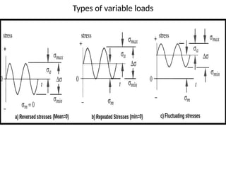
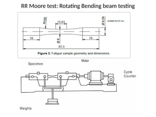
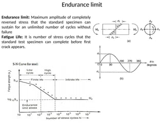
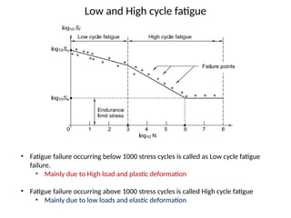
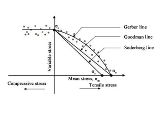
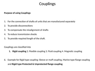
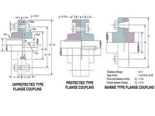
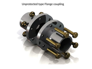
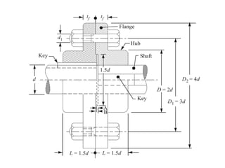
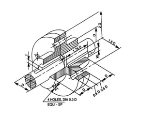
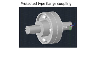
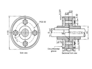
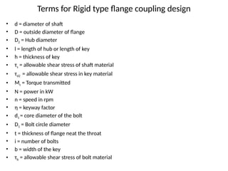
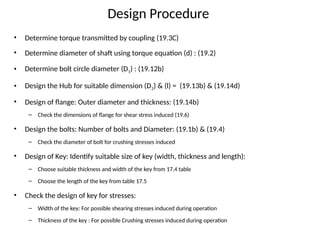
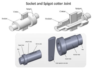
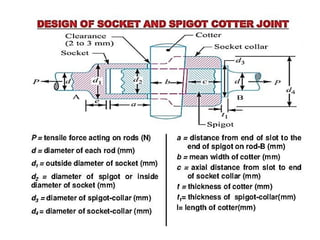
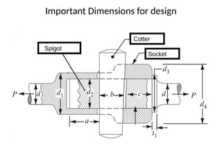
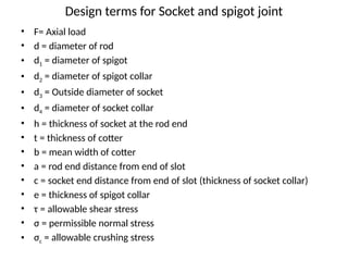
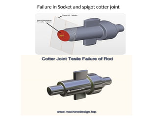
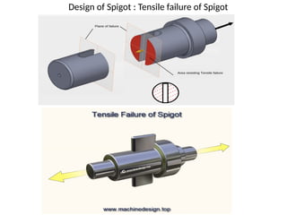
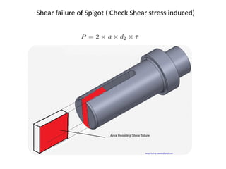
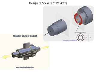
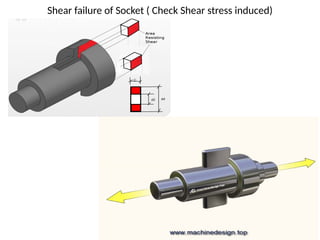
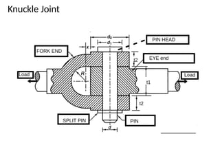
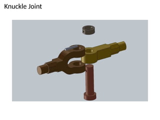
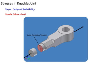
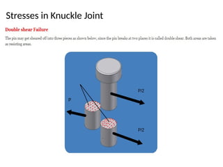
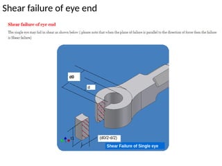
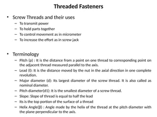
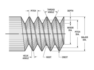
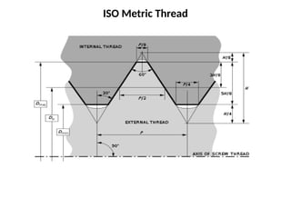
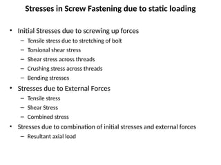
Module 2: Design for Fatigue Strength
Introduction
• In static loading, failure is gradual and has enough time for elongation.
– Ex: Elastic deformation, General yielding, Fracture
• In Fatigue, loading is repeated cyclically. Usually failure begins with minor crack more
likely due to
– Discontinuities, Irregularities and Internal defects
• Since there is no visible deformation in material due to fatigue loading condition, failure
would be catastrophic
• Definition: Damage accumulated through the application of repeated stress cycles
• Variable amplitude loadings cause different levels of fatigue
• Fatigue is cumulative through the life of an engineering element
• Fatigue failure depends on various factors as
– Number of stress cycles, mean stress, stress amplitude, stress concentration,
residual stresses, corrosion and creep.
Three factors play an important role in fatigue failure:
(i) value of tensile stress (maximum),
(ii) magnitude of variation in stress,
(iii) number of cycles.
Geometrical (specimen geometry) and microstructural aspects also play an important role in
determining fatigue life (and failure). Stress concentrators from both these sources have a
deleterious effect. Residual stress can also play a role.
A corrosive environment can have a deleterious interplay with fatigue.
Factors affecting fatigue failure
Factors necessary
to cause fatigue
failure
Large variation/fluctuation in stress
Sufficiently high maximum tensile stress
Sufficiently large number of stress cycles
Typical cyclic loading parameters
• Stress Cycle: It is smallest portion of stress time plot which is
repeated periodically and identically.
• Maximum stress: Largest algebraic stress in a stress cycle
• Minimum stress: Smallest algebraic stress in a stress cycle
• Mean stress: Algebraic mean of the Maximum and Minimum
stress values
• Range of Stress: It is algebraic difference between the maximum
and minimum stress values.
• Stress amplitude or Variable stress:
• Stress ratio: Ratio of minimum stress to Maximum stress value
Types of variable loads
RR Moore test: Rotating Bending beam testing
Endurance limit
Endurance limit: Maximum amplitude of completely
reversed stress that the standard specimen can
sustain for an unlimited number of cycles without
failure
Fatigue Life: It is number of stress cycles that the
standard test specimen can complete before first
crack appears.
Low and High cycle fatigue
• Fatigue failure occurring below 1000 stress cycles is called as Low cycle fatigue
failure.
• Mainly due to High load and plastic deformation
• Fatigue failure occurring above 1000 stress cycles is called High cycle fatigue
• Mainly due to low loads and elastic deformation
Factors effecting Endurance limit
• Surface finish;
• Shape and distribution of inclusions;
• Grain size and direction;
• Specimen or component size;
• Load type;
• Surface treatments;
• Temperature;
• Environment (corrosion).
Soderberg Criteria
Module 3: Design of Joints and Couplings
Presented by : Prof. Manjunath S. B.
Couplings
Purpose of using Couplings
1. For the connection of shafts of units that are manufactured separately
2. To provide disconnections
3. To compensate the misalignment of shafts
4. To reduce transmission shocks
5. To provide required length of the shaft.
Couplings are classified into
1. Rigid coupling 2. Flexible coupling 3. Fluid coupling 4. Magnetic coupling
6. Example for Rigid type coupling: Sleeve or muff coupling, Marine type flange coupling
and Rigid type Protected & Unprotected flange coupling
Unprotected type Flange coupling
Protected type flange coupling
Terms for Rigid type flange coupling design
• d = diameter of shaft
• D = outside diameter of flange
• D2 = Hub diameter
• l = length of hub or length of key
• h = thickness of key
• τs = allowable shear stress of shaft material
• τd2 = allowable shear stress in key material
• Mt = Torque transmitted
• N = power in kW
• n = speed in rpm
• η = keyway factor
• d1 = core diameter of the bolt
• D1 = Bolt circle diameter
• t = thickness of flange neat the throat
• i = number of bolts
• b = width of the key
• τb = allowable shear stress of bolt material
Design Procedure
• Determine torque transmitted by coupling (19.3C)
• Determine diameter of shaft using torque equation (d) : (19.2)
• Determine bolt circle diameter (D1) : (19.12b)
• Design the Hub for suitable dimension (D2) & (l) = (19.13b) & (19.14d)
• Design of flange: Outer diameter and thickness: (19.14b)
– Check the dimensions of flange for shear stress induced (19.6)
• Design the bolts: Number of bolts and Diameter: (19.1b) & (19.4)
– Check the diameter of bolt for crushing stresses induced
• Design of Key: Identify suitable size of key (width, thickness and length):
– Choose suitable thickness and width of the key from 17.4 table
– Choose the length of the key from table 17.5
• Check the design of key for stresses:
– Width of the key: For possible shearing stresses induced during operation
– Thickness of the key : For possible Crushing stresses induced during operation
Design of Socket and Spigot cotter Joint
Socket and Spigot cotter Joint
Important Dimensions for design
Design terms for Socket and spigot joint
• F= Axial load
• d = diameter of rod
• d1 = diameter of spigot
• d2 = diameter of spigot collar
• d3 = Outside diameter of socket
• d4 = diameter of socket collar
• h = thickness of socket at the rod end
• t = thickness of cotter
• b = mean width of cotter
• a = rod end distance from end of slot
• c = socket end distance from end of slot (thickness of socket collar)
• e = thickness of spigot collar
• τ = allowable shear stress
• σ = permissible normal stress
• σc = allowable crushing stress
Failure in Socket and spigot cotter joint
Design of Spigot : Tensile failure of Spigot
Shear failure of Spigot ( Check Shear stress induced)
Design of Socket { ‘d1’,’d4’,’c’}
Shear failure of Socket ( Check Shear stress induced)
Design of Cotter { ‘t’, ‘b’ and ‘l’ of cotter}
Design Procedure
• Design of rod (d) :
– Evaluate axial stress in rod : (17.62)
• Design of spigot and cotter (d1, b, a) :
– Evaluate crushing stress in cotter (17.69),
– Axial stress across slot (17.63)
– double shear stress at rod end (17.66)
• Design of spigot collar (d2, e):
– Evaluate crushing failure in collar(d2) (17.68),
– Shear failure in collar (e) (17.72)
• Design of socket (d3, d4, c, h):
– Socket failure in tension and compression (d3 ) : (17.64)
– Crushing of socket collar (d4 ) : (17.70)
– Shear failure of socket end (c): (17.67)
– Shear failure of socket (h): (17.73)
• Evaluate bending stress in cotter: (17.74)
Sleeve and Cotter joint
P = Load carried by the rods,
d = Diameter of the rods,
d1 = Outside diameter of sleeve,
d2 = Diameter of the enlarged end of rod,
t = Thickness of cotter,
l = Length of cotter,
b = Width of cotter,
a = Distance of the rod end from the beginning to the cotter hole
(inside the sleeve end),
c = Distance of the rod end from its end to the cotter hole,
σt , τ and σc = Permissible tensile, shear and crushing stresses respectively for the
material of the rods and cotter.
Terms in Sleeve and Cotter Joint Design
Knuckle Joint
Knuckle Joint
Stresses in Knuckle Joint
Shear failure of eye end
Threaded Fasteners
• Screw Threads and their uses
– To transmit power
– To hold parts together
– To control movement as in micrometer
– To increase the effort as in screw jack
• Terminology
– Pitch (p) : It is the distance from a point on one thread to corresponding point on
the adjacent thread measured parallel to the axis.
– Lead (l): It is the distance moved by the nut in the axial direction in one complete
revolution.
– Major diameter (d): Its largest diameter of the screw thread. It is also called as
nominal diameter.
– Pitch diameter(d1): It is the smallest diameter of a screw thread.
– Slope: Slope of thread is equal to half the lead
– Its is the top portion of the surface of a thread
– Helix Angle(β) : Angle made by the helix of the thread at the pitch diameter with
the plane perpendicular to the axis.
ISO Metric Thread
Stresses in Screw Fastening due to static loading
• Initial Stresses due to screwing up forces
– Tensile stress due to stretching of bolt
– Torsional shear stress
– Shear stress across threads
– Crushing stress across threads
– Bending stresses
• Stresses due to External Forces
– Tensile stress
– Shear Stress
– Combined stress
• Stresses due to combination of initial stresses and external forces
– Resultant axial load

Presentation on Design for Fatigue strength.pptx

  • 1.
    Module 2: Designfor Fatigue Strength
  • 2.
    Introduction • In staticloading, failure is gradual and has enough time for elongation. – Ex: Elastic deformation, General yielding, Fracture • In Fatigue, loading is repeated cyclically. Usually failure begins with minor crack more likely due to – Discontinuities, Irregularities and Internal defects • Since there is no visible deformation in material due to fatigue loading condition, failure would be catastrophic • Definition: Damage accumulated through the application of repeated stress cycles • Variable amplitude loadings cause different levels of fatigue • Fatigue is cumulative through the life of an engineering element • Fatigue failure depends on various factors as – Number of stress cycles, mean stress, stress amplitude, stress concentration, residual stresses, corrosion and creep.
  • 3.
    Three factors playan important role in fatigue failure: (i) value of tensile stress (maximum), (ii) magnitude of variation in stress, (iii) number of cycles. Geometrical (specimen geometry) and microstructural aspects also play an important role in determining fatigue life (and failure). Stress concentrators from both these sources have a deleterious effect. Residual stress can also play a role. A corrosive environment can have a deleterious interplay with fatigue. Factors affecting fatigue failure Factors necessary to cause fatigue failure Large variation/fluctuation in stress Sufficiently high maximum tensile stress Sufficiently large number of stress cycles
  • 4.
    Typical cyclic loadingparameters • Stress Cycle: It is smallest portion of stress time plot which is repeated periodically and identically. • Maximum stress: Largest algebraic stress in a stress cycle • Minimum stress: Smallest algebraic stress in a stress cycle • Mean stress: Algebraic mean of the Maximum and Minimum stress values • Range of Stress: It is algebraic difference between the maximum and minimum stress values. • Stress amplitude or Variable stress: • Stress ratio: Ratio of minimum stress to Maximum stress value
  • 5.
  • 6.
    RR Moore test:Rotating Bending beam testing
  • 7.
    Endurance limit Endurance limit:Maximum amplitude of completely reversed stress that the standard specimen can sustain for an unlimited number of cycles without failure Fatigue Life: It is number of stress cycles that the standard test specimen can complete before first crack appears.
  • 8.
    Low and Highcycle fatigue • Fatigue failure occurring below 1000 stress cycles is called as Low cycle fatigue failure. • Mainly due to High load and plastic deformation • Fatigue failure occurring above 1000 stress cycles is called High cycle fatigue • Mainly due to low loads and elastic deformation
  • 9.
    Factors effecting Endurancelimit • Surface finish; • Shape and distribution of inclusions; • Grain size and direction; • Specimen or component size; • Load type; • Surface treatments; • Temperature; • Environment (corrosion).
  • 10.
  • 14.
    Module 3: Designof Joints and Couplings Presented by : Prof. Manjunath S. B.
  • 15.
    Couplings Purpose of usingCouplings 1. For the connection of shafts of units that are manufactured separately 2. To provide disconnections 3. To compensate the misalignment of shafts 4. To reduce transmission shocks 5. To provide required length of the shaft. Couplings are classified into 1. Rigid coupling 2. Flexible coupling 3. Fluid coupling 4. Magnetic coupling 6. Example for Rigid type coupling: Sleeve or muff coupling, Marine type flange coupling and Rigid type Protected & Unprotected flange coupling
  • 17.
  • 20.
  • 22.
    Terms for Rigidtype flange coupling design • d = diameter of shaft • D = outside diameter of flange • D2 = Hub diameter • l = length of hub or length of key • h = thickness of key • τs = allowable shear stress of shaft material • τd2 = allowable shear stress in key material • Mt = Torque transmitted • N = power in kW • n = speed in rpm • η = keyway factor • d1 = core diameter of the bolt • D1 = Bolt circle diameter • t = thickness of flange neat the throat • i = number of bolts • b = width of the key • τb = allowable shear stress of bolt material
  • 23.
    Design Procedure • Determinetorque transmitted by coupling (19.3C) • Determine diameter of shaft using torque equation (d) : (19.2) • Determine bolt circle diameter (D1) : (19.12b) • Design the Hub for suitable dimension (D2) & (l) = (19.13b) & (19.14d) • Design of flange: Outer diameter and thickness: (19.14b) – Check the dimensions of flange for shear stress induced (19.6) • Design the bolts: Number of bolts and Diameter: (19.1b) & (19.4) – Check the diameter of bolt for crushing stresses induced • Design of Key: Identify suitable size of key (width, thickness and length): – Choose suitable thickness and width of the key from 17.4 table – Choose the length of the key from table 17.5 • Check the design of key for stresses: – Width of the key: For possible shearing stresses induced during operation – Thickness of the key : For possible Crushing stresses induced during operation
  • 24.
    Design of Socketand Spigot cotter Joint
  • 25.
    Socket and Spigotcotter Joint
  • 27.
  • 28.
    Design terms forSocket and spigot joint • F= Axial load • d = diameter of rod • d1 = diameter of spigot • d2 = diameter of spigot collar • d3 = Outside diameter of socket • d4 = diameter of socket collar • h = thickness of socket at the rod end • t = thickness of cotter • b = mean width of cotter • a = rod end distance from end of slot • c = socket end distance from end of slot (thickness of socket collar) • e = thickness of spigot collar • τ = allowable shear stress • σ = permissible normal stress • σc = allowable crushing stress
  • 29.
    Failure in Socketand spigot cotter joint
  • 30.
    Design of Spigot: Tensile failure of Spigot
  • 31.
    Shear failure ofSpigot ( Check Shear stress induced)
  • 32.
    Design of Socket{ ‘d1’,’d4’,’c’}
  • 33.
    Shear failure ofSocket ( Check Shear stress induced)
  • 34.
    Design of Cotter{ ‘t’, ‘b’ and ‘l’ of cotter}
  • 35.
    Design Procedure • Designof rod (d) : – Evaluate axial stress in rod : (17.62) • Design of spigot and cotter (d1, b, a) : – Evaluate crushing stress in cotter (17.69), – Axial stress across slot (17.63) – double shear stress at rod end (17.66) • Design of spigot collar (d2, e): – Evaluate crushing failure in collar(d2) (17.68), – Shear failure in collar (e) (17.72) • Design of socket (d3, d4, c, h): – Socket failure in tension and compression (d3 ) : (17.64) – Crushing of socket collar (d4 ) : (17.70) – Shear failure of socket end (c): (17.67) – Shear failure of socket (h): (17.73) • Evaluate bending stress in cotter: (17.74)
  • 36.
  • 37.
    P = Loadcarried by the rods, d = Diameter of the rods, d1 = Outside diameter of sleeve, d2 = Diameter of the enlarged end of rod, t = Thickness of cotter, l = Length of cotter, b = Width of cotter, a = Distance of the rod end from the beginning to the cotter hole (inside the sleeve end), c = Distance of the rod end from its end to the cotter hole, σt , τ and σc = Permissible tensile, shear and crushing stresses respectively for the material of the rods and cotter. Terms in Sleeve and Cotter Joint Design
  • 38.
  • 39.
  • 40.
  • 41.
  • 42.
  • 43.
    Threaded Fasteners • ScrewThreads and their uses – To transmit power – To hold parts together – To control movement as in micrometer – To increase the effort as in screw jack • Terminology – Pitch (p) : It is the distance from a point on one thread to corresponding point on the adjacent thread measured parallel to the axis. – Lead (l): It is the distance moved by the nut in the axial direction in one complete revolution. – Major diameter (d): Its largest diameter of the screw thread. It is also called as nominal diameter. – Pitch diameter(d1): It is the smallest diameter of a screw thread. – Slope: Slope of thread is equal to half the lead – Its is the top portion of the surface of a thread – Helix Angle(β) : Angle made by the helix of the thread at the pitch diameter with the plane perpendicular to the axis.
  • 45.
  • 46.
    Stresses in ScrewFastening due to static loading • Initial Stresses due to screwing up forces – Tensile stress due to stretching of bolt – Torsional shear stress – Shear stress across threads – Crushing stress across threads – Bending stresses • Stresses due to External Forces – Tensile stress – Shear Stress – Combined stress • Stresses due to combination of initial stresses and external forces – Resultant axial load