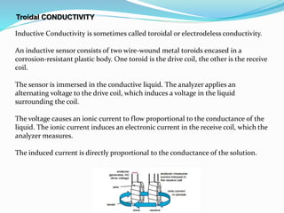
Conductivity measurement involves measuring how well a solution conducts electricity. There are two main types of conductivity sensors:
1. Contacting sensors which use electrodes in contact with the solution and can measure low conductivities. They are susceptible to fouling.
2. Inductive (toroidal) sensors which do not contact the solution and can be used in dirty applications. They require a minimum conductivity of 15 μS/cm.
Proper calibration and temperature compensation are important for accuracy. Contacting sensors are calibrated using standard solutions while inductive sensors require in-situ calibration accounting for installation effects. Temperature compensation considers the nonlinear increase in water conductivity and solute type.
Elemental CHNSO (CHNOS) analysis for determination of carbon, hydrogen, nitrogen, sulfur and oxygen content in petroleum products, biofuels, and more. CHNSO (CHNOS) elemental analyses from Intertek is available for a wide range of products and materials.
Practical Analytical Instrumentation in On-line ApplicationsLiving Online
At the end of this workshop participants will be able to:
Recognise and efficiently troubleshoot a wide variety of industrial analytical measuring instruments
Describe the construction and operation of the most important analytical instruments
Define and explain relevant chemical terminology
Identify sample chemical formulae and symbols
Implement procedures for testing and calibration of analytical instruments
WHO SHOULD ATTEND?
Technicians
Senior operators
Instrumentation and control engineers
Electrical engineers
Project engineers
Design engineers
Process control engineers
Instrumentation sales engineers
Consulting ingenious
Electricians
Maintenance engineers
Systems engineers
MORE INFORMATION: http://www.idc-online.com/content/practical-analytical-instrumentation-line-applications-3
This Course basics of instrumentation and control systems used in oil and gas and petrochemical industry,
The course the following topics
Basics of Instrumentation
Field Instruments
Control Valves
Process Control
Control systems
Slides giving an overview on pH and its measurement.
Contains information about pH meters, its calibration, maintenance , types of ph electrode and modern definition of pH
LARGE SCALE INSTALLATION OF SUBSURFACE DRAINAGE SYSTEM Tushar Dholakia
LARGE SCALE INSTALLATION OF SUBSURFACE DRAINAGE SYSTEM in Chambal Command, Rajasthan - Er. C.M. Tejawat, F.I.E., P. Eng., B.E. (Ag.), M.Sc. (Land Drainage Engineering) Deputy Director (Monitoring), CAD Chambal, Kota (Raj.)
The Role of Drainage Depth and Intensity on Hydrology and Nutrient Loss In th...LPE Learning Center
For more: http://www.extension.org/67691 Water management in the crop root-zone is crucial to successful crop growth and production. Irrigation, surface, and subsurface drainage—and other practices—are routinely implemented throughout the world to improve crop productivity and working conditions of the soil. Water management practices also impact the environmental footprint of agricultural systems by affecting the flow of water, nutrients, sediment, and other constituents through field, farms, and watersheds. Water management practices for agriculture in the Midwestern US should be designed with both profitability and the environment in mind. The design of subsurface (tile) drainage systems has traditionally been more a matter of how much drainage one can afford, rather than the aforementioned objectives. The relationship among subsurface drainage design characteristics (depth, spacing, layout), farm profitability, and environmental impact are not well known at the farm scale. Thus, drainage system design may fail to meet one or more of these important objectives. This presentation will examine the effects of subsurface drainage system design criteria on productivity, profitability, and the environment, using the soils and climatic conditions of the northern corn-belt (southern Minnesota). Water management in the crop root-zone is crucial to successful crop growth and production. Irrigation, surface, and subsurface drainage—and other practices—are routinely implemented throughout the world to improve crop productivity and working conditions of the soil. Water management practices also impact the environmental footprint of agricultural systems by affecting the flow of water, nutrients, sediment, and other constituents through field, farms, and watersheds. Water management practices for agriculture in the Midwestern US should be designed with both profitability and the environment in mind. The design of subsurface (tile) drainage systems has traditionally been more a matter of how much drainage one can afford, rather than the aforementioned objectives. The relationship among subsurface drainage design characteristics (depth, spacing, layout), farm profitability, and environmental impact are not well known at the farm scale. Thus, drainage system design may fail to meet one or more of these important objectives. This presentation will examine the effects of subsurface drainage system design criteria on productivity, profitability, and the environment, using the soils and climatic conditions of the northern corn-belt (southern Minnesota).
Basic Principle of Electrochemical SensorTanvir Moin
Electrochemical sensors are the most versatile and highly developed chemical sensors. Electrochemical sensors are a type of chemical sensor that uses an electrode to detect the concentration of an analyte based on a chemical reaction. They are characterized by their low cost, ease of manufacture, rapid analysis, small size, and ability to detect multiple elements simultaneously. They are also powerful analytical tools because of their: Superior sensitivity and selectivity, Quick response period, Simplicity in operation, and Miniaturization.
The electromagnetic flowmeter is a flowmeter that performs flow measurement according to Faraday’s law of electromagnetic induction. The advantage of the electromagnetic flowmeter is that the pressure loss is extremely small and the measurable flow range is large. The ratio of the maximum flow rate to the minimum flow rate is generally above 40:1. The applicable industrial pipe diameter range is wide, up to 3m. The output signal is linear with the measured flow rate, and the accuracy is high. It can measure the conductivity ≥5μs/cm Fluid flow of acid, alkali, salt solution, water, sewage, corrosive liquid and mud, mineral pulp, paper pulp, etc. But it cannot measure the flow of gas, steam, and pure water.
Experiment 4: Electropolymerized Conducting Polymers.
Introduction:
Conductive polymers (CP) exhibit very useful properties such as flexibility, solubility [1], electrical conductivity, low energy optical transitions, low ionization potential, and high electron affinity.[2] These characterizations make them such effective candidates for many applications such as antistatic and antimagnetic shielding devices[3], microwave attenuation[4], light emitting devices, optical sensors, enzymatic biosensors[5], electronic circuits, and detectors of odors and flavors. The most widely known conducting polymers are polypyrole, polyanaline, and polythiophene. By applying an electrical potential (reversible reaction), these polymers can be reduced. The role of these polymers when they are used as active templates in biosensor applications is the immobilization of dynamic species on the electrode. This will contribute to enhancing the sensitivity and the accuracy of analyte detection. CPs have been used for stabilizing numerous biological species such as enzymes, antibodies, haptens, DNA, and more interestingly the whole cells. [1]
Aim:
The aim of performing this experiment is to create a conducting polypyrrole film which consists of a stabilized enzyme, identify the film and its characteristics, and utilize it as glucose biosensor.
Procedure:
“Refer to Manual for NANO 3101/8302, Electropolymerized Conducting Polymers, Flinders University, p.24-29.”
Results and Discussion:
In the biosensor uses, the deposition of the polymers on the electrode surface can be done by applying an oxidative potential. During this action, the enzymes can be stabilized, and by modifying the deposition time, the amounts of the deposited layer can be recreated. The sensitivity, selectivity, and the accuracy of detection of the biosensors are reliant on the architecture of the polymer, the biological activity of the enzymatic immobilization, and the electropolymerisation circumstances.
In this experiment, the glucose oxidase (enzyme) was immobilized in a conducting polypyrole film on an electrode to find out their appropriateness as a functioning electrode. The performance of the electrode was measured through a Cyclic Voltammogram (CV) of ferricyanide
The geometric area of the electrode was measured by a ruler, and it was found to be 3.14 mm ²which is identical to 0.00314 cm².
The Randles-Sevcik equation is used in the redox reactions
at 25 C °
Where is the peak current, A is the electrode area (cm²), n is the number of electrons involved, C is the concentration of the bulk (mol/ml) for active species, v is the scan rate (V/s), and D is the diffusion coefficient.
n = 1, therefore
, therefore = 0.002756809.
V = 20mV/s = 0.02 V/s, therefore
C = 10 mM = 0.01 mol/L = 0.00001 mol/mL.
can be determined from figure.1
Figure 1: Cyclic Voltammograms (CV) as a function of escalating the scan rate for Platinum Electrode in ferrricyanide solution.
This c ...
KuberTENes Birthday Bash Guadalajara - K8sGPT first impressionsVictor Morales
K8sGPT is a tool that analyzes and diagnoses Kubernetes clusters. This presentation was used to share the requirements and dependencies to deploy K8sGPT in a local environment.
6th International Conference on Machine Learning & Applications (CMLA 2024)ClaraZara1
6th International Conference on Machine Learning & Applications (CMLA 2024) will provide an excellent international forum for sharing knowledge and results in theory, methodology and applications of on Machine Learning & Applications.
Using recycled concrete aggregates (RCA) for pavements is crucial to achieving sustainability. Implementing RCA for new pavement can minimize carbon footprint, conserve natural resources, reduce harmful emissions, and lower life cycle costs. Compared to natural aggregate (NA), RCA pavement has fewer comprehensive studies and sustainability assessments.
Industrial Training at Shahjalal Fertilizer Company Limited (SFCL)MdTanvirMahtab2
This presentation is about the working procedure of Shahjalal Fertilizer Company Limited (SFCL). A Govt. owned Company of Bangladesh Chemical Industries Corporation under Ministry of Industries.
Water billing management system project report.pdfKamal Acharya
Our project entitled “Water Billing Management System” aims is to generate Water bill with all the charges and penalty. Manual system that is employed is extremely laborious and quite inadequate. It only makes the process more difficult and hard.
The aim of our project is to develop a system that is meant to partially computerize the work performed in the Water Board like generating monthly Water bill, record of consuming unit of water, store record of the customer and previous unpaid record.
We used HTML/PHP as front end and MYSQL as back end for developing our project. HTML is primarily a visual design environment. We can create a android application by designing the form and that make up the user interface. Adding android application code to the form and the objects such as buttons and text boxes on them and adding any required support code in additional modular.
MySQL is free open source database that facilitates the effective management of the databases by connecting them to the software. It is a stable ,reliable and the powerful solution with the advanced features and advantages which are as follows: Data Security.MySQL is free open source database that facilitates the effective management of the databases by connecting them to the software.
Online aptitude test management system project report.pdfKamal Acharya
The purpose of on-line aptitude test system is to take online test in an efficient manner and no time wasting for checking the paper. The main objective of on-line aptitude test system is to efficiently evaluate the candidate thoroughly through a fully automated system that not only saves lot of time but also gives fast results. For students they give papers according to their convenience and time and there is no need of using extra thing like paper, pen etc. This can be used in educational institutions as well as in corporate world. Can be used anywhere any time as it is a web based application (user Location doesn’t matter). No restriction that examiner has to be present when the candidate takes the test.
Every time when lecturers/professors need to conduct examinations they have to sit down think about the questions and then create a whole new set of questions for each and every exam. In some cases the professor may want to give an open book online exam that is the student can take the exam any time anywhere, but the student might have to answer the questions in a limited time period. The professor may want to change the sequence of questions for every student. The problem that a student has is whenever a date for the exam is declared the student has to take it and there is no way he can take it at some other time. This project will create an interface for the examiner to create and store questions in a repository. It will also create an interface for the student to take examinations at his convenience and the questions and/or exams may be timed. Thereby creating an application which can be used by examiners and examinee’s simultaneously.
Examination System is very useful for Teachers/Professors. As in the teaching profession, you are responsible for writing question papers. In the conventional method, you write the question paper on paper, keep question papers separate from answers and all this information you have to keep in a locker to avoid unauthorized access. Using the Examination System you can create a question paper and everything will be written to a single exam file in encrypted format. You can set the General and Administrator password to avoid unauthorized access to your question paper. Every time you start the examination, the program shuffles all the questions and selects them randomly from the database, which reduces the chances of memorizing the questions.
We have compiled the most important slides from each speaker's presentation. This year’s compilation, available for free, captures the key insights and contributions shared during the DfMAy 2024 conference.
Sachpazis:Terzaghi Bearing Capacity Estimation in simple terms with Calculati...Dr.Costas Sachpazis
Terzaghi's soil bearing capacity theory, developed by Karl Terzaghi, is a fundamental principle in geotechnical engineering used to determine the bearing capacity of shallow foundations. This theory provides a method to calculate the ultimate bearing capacity of soil, which is the maximum load per unit area that the soil can support without undergoing shear failure. The Calculation HTML Code included.
Literature Review Basics and Understanding Reference Management.pptxDr Ramhari Poudyal
Three-day training on academic research focuses on analytical tools at United Technical College, supported by the University Grant Commission, Nepal. 24-26 May 2024
Saudi Arabia stands as a titan in the global energy landscape, renowned for its abundant oil and gas resources. It's the largest exporter of petroleum and holds some of the world's most significant reserves. Let's delve into the top 10 oil and gas projects shaping Saudi Arabia's energy future in 2024.
Top 10 Oil and Gas Projects in Saudi Arabia 2024.pdf
Conductivity Analyzer
1.
2. Conductivity measurement has widespread use in industrial
applications that involve the detection of contaminants in water and
concentration measurements.
Conductivity measures how well a solution conducts electricity. The
units of conductivity are Siemens/cm (S/cm)
Conductivity
3. Conductivity measurements cover a wide range of solution conductivity
from pure water at less than 1x10⁻⁷ S/cm to values in excess of 1 S/cm for
concentrated solutions .
For convenience, conductivity is usually expressed in the units of
microSiemens/cm (μS/cm, one millionth of a Siemen/cm) or
milliSiemens/cm (mS/cm, one thousandth of a Siemen/cm)
4. Conductive Solutions
Conductivity is typically measured in aqueous (water) solutions of
electrolytes.
Electrolytes are substances that ionize separate into charged particles called
ions.
The ions formed in solution are responsible for carrying the electric current.
Electrolytes include acids, bases, and salts.
5. Conductivity is Non-specific
A conductivity measurement responds to any and all ions present in a solution.
A solution cannot be identified, or its concentration known, from conductivity
alone .
In certain cases, the concentration of an electrolyte in solution can be
determined by conductivity if the composition of the solution is known.
7. CONTACTING CONDUCTIVITY
Contacting conductivity uses a sensor with two metal or graphite
electrodes in contact with the electrolyte solution. An AC voltage is
applied to the electrodes by the conductivity analyzer, and the resulting
AC current that flows between the electrodes is used to determine the
conductance.
8. Probe Constant:
The amount of current that flows between the electrodes depends not
only on the solution conductivity, but also on the length, surface area,
and geometry of the sensor electrodes. The probe constant (also
called "sensor constant" or "cell constant") is a measure of the current
response of a sensor to a conductive solution, due to the sensor’s
dimensions and geometry. Its units are cm-1 (length divided by area),
and the probe constant necessary for a given conductivity range is
based on the particular conductivity analyzer's measuring circuitry.
Probe constants can vary from 0.01 cm-1 to 50 cm-1 and, in general,
the higher the conductivity, the large the probe constant necessary.
Characteristics of Contacting Conductivity
Contacting conductivity can measure down to pure water conductivity. Its
main drawback is that the sensor is susceptible to coating and corrosion,
which drastically lowers the reading. In strongly conductive solutions.
9. Temperature Effects
The conductivity of a solution typically increases with temperature. In
moderately and highly conductive solutions, this increase can be
compensated for using a linear equation involving a temperature
coefficient (K), which is the percent increase in conductivity per degree
centigrade. The temperature coefficients of the following electrolytes
generally fall in the ranges shown below:
Acids 1.0 - 1.6%/°C
Bases 1.8 - 2.2%/°C
Salts 2.2 - 3.0%/°C
Fresh water 2.0%/°C
10.
11. Temperature Compensation in High Purity Water
In solutions with a conductivity of 1 μS/cm or less, the conductivity
increase with temperature is highly nonlinear.
Conductivity applications, at or below 1.0 μS/cm, require high purity
temperature compensation to avoid large errors.
This occurs because the conductivity of water itself is a large fraction of
the overall conductivity.
Temperature compensation for these solutions must not only take into
account the increase in the conductivity of water, but also the increase in
conductivity of the solute (dissolved electrolyte).
The increase in the conductivity due to the solute will also depend upon
what type of electrolyte is present, i.e., acid, base, or salt.
12. CONDUCTIVITY CALIBRATION
Moderate to High Range Measurements
For conductivity measurements in excess of 100 μS/cm, a conductivity
standard may be used to calibrate a conductivity loop. The conductivity
measurement may also be calibrated using grab sample standardization.
Care must be taken that the correct temperature coefficient is being used
in both the on-line instrument and the referee instrument to avoid
discrepancies based on temperature compensation errors.
13. CONDUCTIVITY CALIBRATION
High Purity Water Measurements
Conductivity samples below 100 μS/cm are highly susceptible to
contamination by trace contaminants in containers and by CO2 in air.
As a result, calibration with a conventional standard is not advisable.
Many conductivity instruments designed for high purity water
measurements include a calibration routine for entering the constant
of the conductivity sensor.
The conductivity sensor used with this kind of instrument must have
its sensor constant accurately measured using a conductivity standard
in a higher range.
Once the sensor constant is entered into the instrument, the
conductivity loop is calibrated.
A second method is to calibrate the on-line instrument to a suitably
calibrated, referee instrument in a closed flow loop.
14. CONDUCTIVITY APPLICATIONS
•Non-Specific Applications
Non-specific applications involve simply measuring conductivity to
detect the presence of electrolytes.
The majority of conductivity applications fall within this category. They
include monitoring and control of demineralization, leak detection, and
monitoring to a prescribed conductivity specification. In most instances,
there is a maximum acceptable concentration of electrolyte, which is
related to a conductivity value, and that conductivity value is used as an
alarm point.
15. Concentration Measurements
Conductivity is non-specific, even though it can sometimes be applied to
concentration measurements if the composition of the solution and its
conductivity behavior is known.
The first step is to know the conductivity of the solution as a function of
the concentration of the specie of interest. This data can come from
published conductivity vs. concentration curves for electrolytes, or from
laboratory measurements. The conductivity of mixtures usually requires a
laboratory measurement, due to the scarcity of published conductivity
data on mixed electrolytes.
Over large concentration ranges, conductivity will increase with
concentration, but may then reach a maximum and then decrease with
increasing concentration.
It is important to use conductivity data over the temperature range of the
process, because the shape of the conductivity vs. concentration curve
will change with temperature, and a concentration measurement may be
possible at one temperature but not at another.
17. SUMMARY
Conductivity is the ability of a solution to conduct electricity.
Conductivity measurement can be applied to the full range of water
solutions, from high purity water to the most conductive solutions
known.
Things to consider in applying conductivity:
1. Use contacting conductivity for low conductivity applications in clean
process streams.
2. For accuracy in applications approaching 1 μS/cm, use contacting
conductivity with high purity water temperature compensation.
3. Use toroidal conductivity for dirty, corrosive, or high conductivity
applications.
4. If a concentration measurement is required, the full stream
composition, as well as its conductivity behavior over the desired
concentration and temperature range must be known. If a reliable
estimate cannot be made from published data, data must be gathered in
the laboratory.
18. Inductive Conductivity is sometimes called toroidal or electrodeless conductivity.
An inductive sensor consists of two wire-wound metal toroids encased in a
corrosion-resistant plastic body. One toroid is the drive coil, the other is the receive
coil.
The sensor is immersed in the conductive liquid. The analyzer applies an
alternating voltage to the drive coil, which induces a voltage in the liquid
surrounding the coil.
The voltage causes an ionic current to flow proportional to the conductance of the
liquid. The ionic current induces an electronic current in the receive coil, which the
analyzer measures.
The induced current is directly proportional to the conductance of the solution.
Troidal CONDUCTIVITY
19. The current in the receive coil depends on the number of windings in the
drive and receive coils and the physical dimensions of the sensor.
The number of windings and the dimensions of the sensor are described by
the cell constant.
As in the case of contacting sensors, the product of the cell constant and
conductance is the conductivity.
20. The walls of the tank or pipe in which the sensor is installed also influence
the cell constant—the so-called wall effect.
A metal (conducting) wall near the sensor increases the induced current,
leading to increased conductance and a corresponding decrease in the cell
constant.
A plastic or insulating wall has the opposite effect. Normally, wall effects
disappear when the distance between the sensor and wall reaches roughly
three-fourths of the diameter of the sensor.
For accurate results, the user must calibrate the sensor in place in the
process piping
21. .
The inductive measurement has several benefits
• First, the toroids do not need to touch the sample. Thus, they can be
encased in plastic, allowing the sensor to be used in solutions that would
corrode metal electrode sensors.
• Second, because inductive sensors tolerate high levels of fouling, they
can be used in solutions containing high levels of suspended solids. As
long as the fouling does not appreciably change the area of the toroid
opening, readings will be accurate.
• High conductivity solutions produce a large, easily measured induced
current in the receive coil. Inductive sensors do have drawbacks. Chiefly,
they are restricted to samples having conductivity greater than about 15
µS/cm.They cannot be used for measuring low conductivity solutions.
22. Some features of CR200 THRONTON
1. Measure four signals and compute four measurements.
2. Check setpoints against the measurements.
3. Control the relays.
4. Update analog output signals.
5. Transmit measurement data over the communication port.
6. Display data (if not displaying menu).
23. •Linear Compensation
The raw resistance measurement is compensated by multiplication
with a factor expressed as a “% per °C” (deviation from 25°C). The
range is 0 - 99%/°C with a default value of 2%/°C.
•Standard Compensation
The standard compensation method includes compensation for non-
linear high purity effects as well as conventional neutral salt
impurities and conforms to ASTM standards D1125 and D5391.
Temperature Compensation
Some types of temperature compensation:
28. Calibration of 5081-C-HT
1. With the sensor in a standard solution of known
conductivity value, allow the temperature of the sensor to
stabilize (10 min).
2. To access the CALIbrAtE menu, press the CAL button
on the IRC.
3. Press ENTER to access the CAL segment with flashing
prompt.
4. Use the IRC editing keys to indicate the conductivity
values of the standard solution on the screen.
5. Press ENTER then EXIT to enter the standard solution
value and return to the main screen.
29. Sensor 0
From the main screen, press CAL, then press NEXT to
enter the SEnSOr 0 menu. Press ENTER to access the
SEnSOr 0 sub-menu. With the sensor attached and in
air, press ENTER again to zero the sensor. Press EXIT
to return to the SEnSOr 0 sub-menu.
30. Temp Adj
1. Press NEXT and then ENTER to access the tEMP sub-
menu with flashing prompt. With the sensor in any
solution of known temperature, allow the temperature of
the sensor to stabilize. Use the editing keys of the IRC to
change the displayed value as needed.
2. Press ENTER to standardize the temperature reading
and return to the tEMP AdJ screen.
31. Cell Constant
1. When the CALibrAtE sub-menu has been accessed,
press NEXT four (4) times and then ENTER to access the
CELLCOnSt menu segment with the flashing cell constant
prompt.
2. Using the arrow keys on the IRC, enter your sensor’s cell
constant as indicated on the sensor’s tag or specification
sheet.
3. Press ENTER to save the cell constant into the transmitter
memory and return to the CELL COnSt sub-menu.
32. Temp Slope
1. Press NEXT to enter the tEMP SLOPE menu.
The correct temperature slope must be entered into the
transmitter to ensure an acceptable process variable
measurement under fluctuating process temperature
conditions. Enter the slope in measured conductivity units per
degree temperature change using the IRC’s arrow keys.
Press ENTER to enter the slope into memory; then press
EXIT to return to the main screen.
2. If the temperature slope of the process is not known but
you wish to approximate it, refer to the following guide and
press ENTER to proceed on to tSLOPE sub-menu with
flashing prompt. Utilize the IRC editing keys to generate
the desired slope value. Press ENTER then EXIT to return to
the main screen.
Acids: 1.0 to 1.6% per °C
Bases: 1.8 to 2.2% per °C
Salts: 2.2 to 3.0% per °C
Water: 2.0% per °C