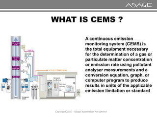
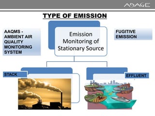
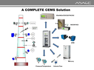
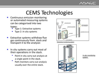
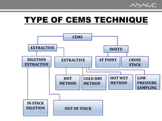
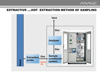
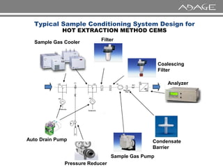
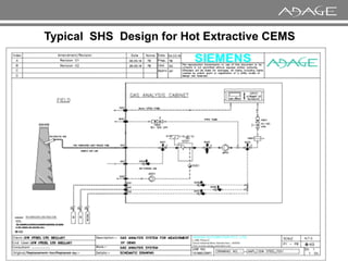
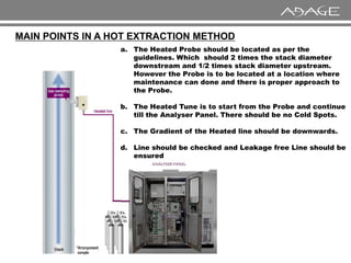
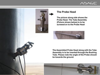
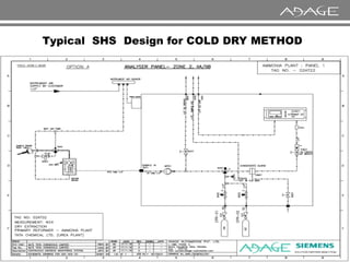
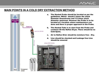
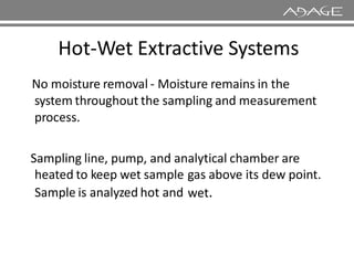
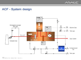
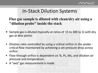
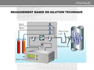
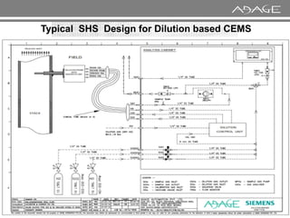
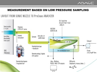
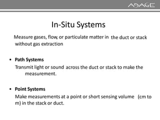
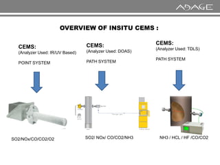
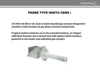
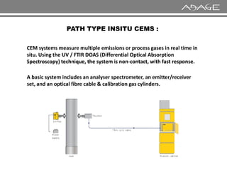
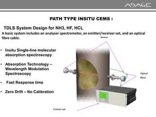
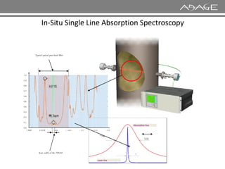
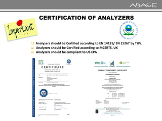
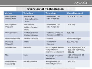
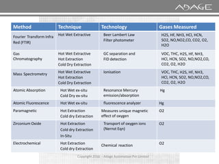
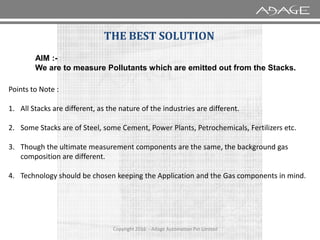
The document discusses continuous emission monitoring systems (CEMS). It describes CEMS as equipment used to continuously determine the concentration of gas or particulate matter emissions from stationary sources like smokestacks. It outlines different types of CEMS including extractive systems that withdraw gas samples and in-situ systems that perform measurements inside the stack. Common CEMS technologies are also summarized, such as extractive, dilution, and in-situ systems. Key aspects of CEMS calibration and its importance are highlighted.
ENVEA designs and produces a complete range of state of the art CEMS gas and dust analyzers, sampling systems, data acquisition systems and software for the continuous measurement & reporting of stack pollutants.
With the global focus on emissions, the Group helps its clients quickly achieve environmental compliance in the most cost-effective manner.
Industrial emissions monitoring regulations vary from country to country, and the measurement technology must be assessed for suitability and in accordance with local requirements and standards.
Our solutions are fully compliant with the latest European and International regulations & standards.
Flue gas desulfurization is commonly known as FGD and is the technology used for removing sulfur dioxide (SO2) from the exhaust combustion flue gases of power plants that burn coal or oil to produce steam for the turbines that drive their electricity generators.
Episode 3 : Production of Synthesis Gas by Steam Methane ReformingSAJJAD KHUDHUR ABBAS
Episode 3 : Production of Synthesis Gas by Steam Methane Reforming
History of Synthesis Gas
In 1780, Felice Fontana discovered that combustible gas develops if water vapor is passed over carbon at temperatures over 500 °C. This CO and H2 containing gas was called water gas and mainly used for lighting purposes in the19th century.
As of the beginning of the 20th century, H2/CO-mixtures were used for syntheses of hydrocarbons and then, as a consequence, also called synthesis gas.
Haber and Bosch discovered the synthesis of ammonia from H2 and N2 in 1910 and the first industrial ammonia synthesis plant was commissioned in 1913.
The production of liquid hydrocarbons and oxygenates from syngas conversion over iron catalysts was discovered in 1923 by Fischer and Tropsch.
Much of the syngas conversion processes were being developed in Germany during the first and second world wars at a time when natural resources were becoming scare and alternative routes for hydrogen production, ammonia synthesis, and transportation fuels were a necessity.
In 1943/44, this was applied for large-scale production of artificial fuels from synthesis gas in Germany.
Amine Gas Treating Unit - Best Practices - Troubleshooting Guide Gerard B. Hawkins
Amine Gas Treating Unit Best Practices - Troubleshooting Guide for H2S/CO2 Amine Systems
Contents
Process Capabilities for gas treating process
Typical Amine Treating
Typical Amine System Improvements
Primary Equipment Overview
Inlet Gas Knockout
Absorber
Three Phase Flash Tank
Lean/Rich Heat Exchanger
Regenerator
Filtration
Amine Reclaimer
Operating Difficulties Overview
Foaming
Failure to Meet Gas Specification
Solvent Losses
Corrosion
Typical Amine System Improvements
Degradation of Amines and Alkanolamines during Sour Gas Treating
APPENDIX
Best Practices - Troubleshooting Guide
This is great Presentation with 3D effects which is all about production of ammonia from natural gas.
I am damn sure you will be getting everything here searching for.
its better to download it and then run in powerpoint 2013.
Source: Honeywell
Gas detection basics
Gas detection sensing technology
Sensor location
SIL in gas detection
Calibration / maintenance
ATEX
www.ie-net.be/reg
www.regeltechnieken.org
High level introduction
Mainstream syngas = steam reforming processes
Ammonia; methanol; hydrogen/HyCO
Town gas
Steam reforming; low pressure cyclic
Direct reduction iron (DRI)
HYL type processes; Midrex type processes
Most modern ammonia processes are based on steam-reforming of natural gas or naphtha.
The 3 main technology suppliers are Uhde (Uhde/JM Partnership), Topsoe & KBR.
The process steps are very similar in all cases.
Other suppliers are Linde (LAC) & Ammonia Casale.
Steam and water analysis system is designed for corrosion control in boiler and turbine in power station. To protect equipment from corrosion SWAS work in stages like Sample Extracting, Sample Transport, Sample Conditioning, and sample Analysis.
Cement plants require continuous monitoring of the process and product.
From incoming ore to blending the clinker not only is the product being analyzed (CaO, SiO2, Al2O3, etc) but a series of analyzers are monitoring the gases created throughout the process. Coal bins & mills, pre-heat towers, and calciners are monitored for CO and O2, the kiln is monitored for a series of gases (CO, NO, O2, CH4, CO2, SO2), baghouses are monitored for dust and particulate and the CEMs equipment monitors (flow, particulate, CO, NOx, SO2, O2, H2O, HCl, HF, VOC, … ) for compliance and as a last look at the process.
Whether it is the ore or clinker you're looking to analyze, the gases created in your kiln, the emissions out your stack or any of the places in-between, CEMSI provides full-site knowledge of cement production and wisdom in maximizing your product, safety, process and emission monitoring equipment and service.
The CEMSI cement solutions guide gives an overview of where you can expect our experts to help reduce capital and operating costs. CEM Specialties Inc (CEMSI) has supported cement for over 25 years with sales, service, parts, and expertise and has expanded our offerings to provide cement plants with better technology, increased up-time and confidence in their equipment.
Direct Mercury Analyzer for analysis of liquid, solid and gaseous samples
DMA which uses the principle of thermal decomposition, amalgamation and atomic absorption.
The DMA-80 can analyze solid, liquid and gas matrices with equal precision.
All mercury is released from the sample through thermal decomposition.
This eliminates the need for any sample preparation.
It is a multi-element analysis technique that will separate a sample into its constituent atoms and ions and excite it to a higher energy level.
Cause them to emit light with a distinct wavelength, which will be analyzed.
Water scarcity is the lack of fresh water resources to meet the standard water demand. There are two type of water scarcity. One is physical. The other is economic water scarcity.
Welcome to WIPAC Monthly the magazine brought to you by the LinkedIn Group Water Industry Process Automation & Control.
In this month's edition, along with this month's industry news to celebrate the 13 years since the group was created we have articles including
A case study of the used of Advanced Process Control at the Wastewater Treatment works at Lleida in Spain
A look back on an article on smart wastewater networks in order to see how the industry has measured up in the interim around the adoption of Digital Transformation in the Water Industry.
Hybrid optimization of pumped hydro system and solar- Engr. Abdul-Azeez.pdffxintegritypublishin
Advancements in technology unveil a myriad of electrical and electronic breakthroughs geared towards efficiently harnessing limited resources to meet human energy demands. The optimization of hybrid solar PV panels and pumped hydro energy supply systems plays a pivotal role in utilizing natural resources effectively. This initiative not only benefits humanity but also fosters environmental sustainability. The study investigated the design optimization of these hybrid systems, focusing on understanding solar radiation patterns, identifying geographical influences on solar radiation, formulating a mathematical model for system optimization, and determining the optimal configuration of PV panels and pumped hydro storage. Through a comparative analysis approach and eight weeks of data collection, the study addressed key research questions related to solar radiation patterns and optimal system design. The findings highlighted regions with heightened solar radiation levels, showcasing substantial potential for power generation and emphasizing the system's efficiency. Optimizing system design significantly boosted power generation, promoted renewable energy utilization, and enhanced energy storage capacity. The study underscored the benefits of optimizing hybrid solar PV panels and pumped hydro energy supply systems for sustainable energy usage. Optimizing the design of solar PV panels and pumped hydro energy supply systems as examined across diverse climatic conditions in a developing country, not only enhances power generation but also improves the integration of renewable energy sources and boosts energy storage capacities, particularly beneficial for less economically prosperous regions. Additionally, the study provides valuable insights for advancing energy research in economically viable areas. Recommendations included conducting site-specific assessments, utilizing advanced modeling tools, implementing regular maintenance protocols, and enhancing communication among system components.
Saudi Arabia stands as a titan in the global energy landscape, renowned for its abundant oil and gas resources. It's the largest exporter of petroleum and holds some of the world's most significant reserves. Let's delve into the top 10 oil and gas projects shaping Saudi Arabia's energy future in 2024.
Cosmetic shop management system project report.pdfKamal Acharya
Buying new cosmetic products is difficult. It can even be scary for those who have sensitive skin and are prone to skin trouble. The information needed to alleviate this problem is on the back of each product, but it's thought to interpret those ingredient lists unless you have a background in chemistry.
Instead of buying and hoping for the best, we can use data science to help us predict which products may be good fits for us. It includes various function programs to do the above mentioned tasks.
Data file handling has been effectively used in the program.
The automated cosmetic shop management system should deal with the automation of general workflow and administration process of the shop. The main processes of the system focus on customer's request where the system is able to search the most appropriate products and deliver it to the customers. It should help the employees to quickly identify the list of cosmetic product that have reached the minimum quantity and also keep a track of expired date for each cosmetic product. It should help the employees to find the rack number in which the product is placed.It is also Faster and more efficient way.
Industrial Training at Shahjalal Fertilizer Company Limited (SFCL)MdTanvirMahtab2
This presentation is about the working procedure of Shahjalal Fertilizer Company Limited (SFCL). A Govt. owned Company of Bangladesh Chemical Industries Corporation under Ministry of Industries.
Hierarchical Digital Twin of a Naval Power SystemKerry Sado
A hierarchical digital twin of a Naval DC power system has been developed and experimentally verified. Similar to other state-of-the-art digital twins, this technology creates a digital replica of the physical system executed in real-time or faster, which can modify hardware controls. However, its advantage stems from distributing computational efforts by utilizing a hierarchical structure composed of lower-level digital twin blocks and a higher-level system digital twin. Each digital twin block is associated with a physical subsystem of the hardware and communicates with a singular system digital twin, which creates a system-level response. By extracting information from each level of the hierarchy, power system controls of the hardware were reconfigured autonomously. This hierarchical digital twin development offers several advantages over other digital twins, particularly in the field of naval power systems. The hierarchical structure allows for greater computational efficiency and scalability while the ability to autonomously reconfigure hardware controls offers increased flexibility and responsiveness. The hierarchical decomposition and models utilized were well aligned with the physical twin, as indicated by the maximum deviations between the developed digital twin hierarchy and the hardware.
2. WHAT IS CEMS ?
A continuous emission
monitoring system (CEMS) is
the total equipment necessary
for the determination of a gas or
particulate matter concentration
Copyright 2016 - Adage Automation Pvt Limited
particulate matter concentration
or emission rate using pollutant
analyser measurements and a
conversion equation, graph, or
computer program to produce
results in units of the applicable
emission limitation or standard
6. CEMS Technologies
Continuous emission monitoring
can be categorised into two
types:
or automated measuring systems
Type 1: Extractive systems
Type 2: In situ systems
Extractive systems withdraw flue
transport it to the analyser
.
gas continuously from stack and Extractive monitoring system
In situ systems carry out most of
their operations in the stack.
Point in situ carry out analysis at
a single point in the stack.
Path monitors carry out analysis
usually over the entire stack.
In situ monitoring
system.
7. CEMS
EXTRACTIVE INSITU
DILUTION EXTRACTIVE AT POINT CROSS
TYPE OF CEMS TECHNIQUE
DILUTION
EXTRACTIVE
EXTRACTIVE
IN STACK
DILUTION OUT OF STACK
HOT
METHOD
COLD DRY
METHOD
AT POINT CROSS
STACK
HOT WET
METHOD
LOW
PRESSURE
SAMPLING
9. Typical Sample Conditioning System Design for
HOT EXTRACTION METHOD CEMS
Sample Gas Cooler
Filter
Coalescing
Filter
Analyzer
Analyzer
Condensate
Barrier
Pressure Reducer
Sample Gas Pump
Auto Drain Pump
11. MAIN POINTS IN A HOT EXTRACTION METHOD
a. The Heated Probe should be located as per the
guidelines. Which should 2 times the stack diameter
downstream and 1/2 times stack diameter upstream.
However the Probe is to be located at a location where
maintenance can done and there is proper approach to
the Probe.
b. The Heated Tune is to start from the Probe and continue
till the Analyser Panel. There should be no Cold Spots.
c. The Gradient of the Heated line should be downwards.
d. Line should be checked and Leakage free Line should be
ensured
12. The Probe Head
The picture along side shows the
Probe Head. The Tube Assembly
(Picture shown below) is to be
screwed on to the Probe Head
The Assembled Probe Head along with the Tube
Assembly is to be inserted through the Bushing
Tube. Please note the angle of the Probe should
be towards the ground.
15. Cool-Dry Extractive Systems
Sample gas is extracted and conditioned to remove moisture
prior to analysis. Options:
• Conditioning at the CEM shelter
Heated sample line is required to keep the wet sample above its
dew point until it reaches the water removal system
Conditioning at the stack
Water is removed at the stack - no heated line - commonly used
by source testers for short-term sampling
•
16. Nafion Dryer based Measurements
Tube
Tube-
-in
in-
-shell, heat and
shell, heat and
moisture exchanger
moisture exchanger
To increase drying capacity,
simply increase the surface
area (wider, longer or
area (wider, longer or more
more
tubes)
tubes)
19. a. The Heated Probe should be located as per the
guidelines. Which should 2 times the stack
diameter downstream and 1/2 times stack
diameter upstream. However the Probe is to be
located at a location where maintenance can
done and there is proper approach to the Probe.
b. The Heated Tube is to start from the Probe and
continue till the Nafion Dryer. There should be no
Cold Spots.
c. Air to Nafion Drier should be moisture free – Dry.
d. Line should be checked and Leakage free Line
MAIN POINTS IN A COLD DRY EXTRACTION METHOD
d. Line should be checked and Leakage free Line
should be ensured
20. Hot-Wet Extractive Systems
No moisture removal - Moisture remains in the
system throughout the sampling and measurement
process.
Sampling line, pump, and analytical chamber are
heated to keep wet sample
Sample is analyzed hot and
gas above
wet.
its dew point.
21.
22. In-Stack Dilution Systems
Flue gas sample is diluted with clean/dry air using a
"dilution probe" inside the stack
• Sample gas is diluted (typically at ratios of
gas at dew points
15 to 300 to 1) with dry
gas at dew points
• Dilution ratio controlled by using a critical orifice in the probe -
critical flow maintained by achieving a set pressure drop across
orifice
Flow through orifice is dependent on Ts, Ps, Ms, and dilution air
pressure and temperature.
A "wet" gas measurement is made
•
•
23. Out-of-Stack Dilution Systems
Flue gas sample is diluted with clean/dry air using dilution "box"
close-coupled or otherwise outside of the stack
• Dilution ratio controlled by using a critical orifice in the box - critical
flow maintained by achieving a set pressure drop across orifice
•
flow maintained by achieving a set pressure drop across orifice
Sample gas is diluted (typically at ratios of 15 to 300 to 1) with dry gas
at dew points typically at
- 40° C
Flow through orifice is dependent on Ps, Ms, and dilution air pressure
and temperature.
A "wet" gas measurement is made
•
•
•
26. Low Pressure Sampling
• The measuring principle works on a low pressure sample (LPS). The
sampling system consists of a SONIC NOZZLE. It is an original system
which can collect and convey the sample from 50 to 200 mbar abs from
the sampling point to the analyzer.
• The sample is taken at a very low pressure (50 to 200 mbar absolute). This
feature enables us to reduce the vapor pressure of the sample at the level
of the sampling point. At the pressure of the sampling, the ambient
•
of the sampling point. At the pressure of the sampling, the ambient
temperature is almost always above the dew point. There is no risk of
condensation, which eliminates the need for a heated line and a cooler.
Thanks to this technique, we do not distort the sample.
• The sample is taken with a flow rate of 1 to 24 l/h. However, since the
pressure of the sample in the duct is 10 times lower than the atmospheric
pressure (100 mbar abs), the transfer speed is multiplied by 10. The
transfer rate of the sample ranges therefore between 10 to 240 l/h.
Since only a little flow amount is collected, the system hardly gets dirty,
requiring limited maintenance of the analysis chain.
•
28. In-Situ Systems
Measure gases, flow, or particulate matter in
without gas extraction
the duct or stack
• Path Systems
• Path Systems
Transmit light or sound
measurement.
across the duct or stack to make the
• Point Systems
Make measurements at a point or short sensing volume
m) in the stack or duct.
(cm to
29. OVERVIEW OF INSITU CEMS :
CEMS:
(Analyzer Used: IR/UV Based)
POINT SYSTEM
CEMS:
(Analyzer Used: DOAS)
PATH SYSTEM
CEMS:
(Analyzer Used: TDLS)
PATH SYSTEM
SO2/NOx/CO/CO2/O2 SO2/ NOx/ CO/CO2/NH3 NH3 / HCL / HF /CO/CO2
30. An infra-red (IR) or UV, duct or stack-mounted gas analyser designed to
provide in-stack analysis of, gas-phase emission components.
PROBE TYPE INSITU CEMS :
A typical system comprises an in-situ mounted analyser, an integral
calibration function and a Control Unit with options which include a
powerful in-situ Heater and calibration gas cyinders
31. CEM systems measure multiple emissions or process gases in real time in
situ. Using the UV / FTIR DOAS (Differential Optical Absorption
Spectroscopy) technique, the system is non-contact, with fast response.
PATH TYPE INSITU CEMS :
A basic system includes an analyser spectrometer, an emitter/receiver
set, and an optical fibre cable & calibration gas cylinders.
32. PATH TYPE INSITU CEMS :
Sensors
TDLS System Design for NH3, HF, HCL
• Insitu Single-line molecular
absorption spectroscopy
A basic system includes an analyser spectrometer, an emitter/receiver set, and an optical
fibre cable.
Optical
fibers
Central unit
• Absorption Technology –
Wavelength Modulation
Spectroscopy
• Fast Response time
• Zero Drift – No Calibration
33. Typical optical pass band filter
In-Situ Single Line Absorption Spectroscopy
Scan width of the TDLAS
Absorption line
Absorption line
Laser line
Laser line
34. CERTIFICATION OF ANALYZERS
Analyzers should be Certified according to EN 14181/ EN 15267 by TUV.
Analyzers should be Certified according to MCERTS, UK
Analyzers should be compliant to US EPA
37. Method Technique Technology Gases Measured
Fourier Transform Infra
Red (FTIR)
Hot Wet Extractive Beer Lambert Law
Filter photometer
H2S, HF, NH3, HCl, HCN,
SO2, NO,NO2,CO, CO2, O2,
H2O
Gas
Chromatography
Hot Wet Extractive
Hot Extraction
Cold Dry Extraction
GC separation and
FID detection
VOC, THC, H2S, HF, NH3,
HCl, HCN, SO2, NO,NO2,CO,
CO2, O2, H2O
Mass Spectrometry Hot Wet Extractive
Hot Extraction
Cold Dry Extraction
Ionisation VOC, THC, H2S, HF, NH3,
HCl, HCN, SO2, NO,NO2,CO,
CO2, O2, H2O
Copyright 2016 - Adage Automation Pvt Limited
Cold Dry Extraction CO2, O2, H2O
Atomic Absorption Hot Wet ex-situ
Cold Dry ex-situ
Resonance Mercury
emission/absorption
Hg
Atomic Fluorescence Hot Wet ex-situ fluorescence analyzer Hg
Paramagnetic Hot Extraction
Cold dry Extraction
Measures unique magnetic
effect of oxygen
O2
Zirconium Oxide Hot Extraction
Cold dry Extraction
In-Situ
Transport of oxygen ions
(Nernst Eqn)
O2
Electrochemical Hot Extraction
Cold dry Extraction
Chemical reaction O2
38. Points to Note :
1. All Stacks are different, as the nature of the industries are different.
THE BEST SOLUTION
AIM :-
We are to measure Pollutants which are emitted out from the Stacks.
Copyright 2016 - Adage Automation Pvt Limited
2. Some Stacks are of Steel, some Cement, Power Plants, Petrochemicals, Fertilizers etc.
3. Though the ultimate measurement components are the same, the background gas
composition are different.
4. Technology should be chosen keeping the Application and the Gas components in mind.
39. 1. The Temperature of the Stack.
2. The Moisture Content in the Stack.
3. Dew Point Of Sample Gas
POINTS TO CONSIDER
Copyright 2016 - Adage Automation Pvt Limited
4. The Dust Content in the Stack.
5. The Presence of Corrosive Components in the Gas.
6. The Range of the Analyser.
7. The Area Classification, ( Safe Area or in Zone)
8. What is the maintenance requirement of the Analyser.
40. Calibration Of an Analyser ensures that the Analyser is reading the Certified Gas
Correctly. Hence it can be concluded when the Stack gas is fed in the Analyser after
calibration the concentration displayed would be correct.
CALIBRATION
Copyright 2016 - Adage Automation Pvt Limited
calibration the concentration displayed would be correct.
41. WHAT ARE THE MAJOR ITEMS NEEDED FOR
CALIBRATION
1. Certified Calibration Gas Cylinders.
2. The Calibration Cylinders should have a valid Certificate. In case dates have expired
the Cylinder needs to be refilled and revalidated.
3. There should be a Zero Gas Cylinder.
Copyright 2016 - Adage Automation Pvt Limited
3. There should be a Zero Gas Cylinder.
4. There Should be a Span Gas Cylinder. ( The Value of the Span Gas Cylinder should
be around 80% of the measuring Range of the Analyser.
5. The Gas Analysis System should have facility to allow the possibility of passing
Calibration Gas in the Analyser and performing calibration.
42. TYPES OF CALIBRATION
Manual Calibration :-
This means that a person is in front of the Analyser System, he opens the Calibration
Cylinders and lets the gasses pass through the Analyser, and once the readings in the
Analyser has stabilised, He performs calibration.
Copyright 2016 - Adage Automation Pvt Limited
Automatic Calibration :-
This is termed so that the calibration is performed by the Analyser Automatically.
Now this Automatic Calibration can be triggered in Two ways :
1. The Calibration can be time based
2. The Calibration can be triggered by external input.
43. AUTOMATIC CALIBRATION
Some Analysers are equipped with calibration Cuvette.
These Cuvettes are pre filled in the Factory with the zero and Span Gases.
During Automatic Calibration, these cuvette come in line with the IR beam. The Analyser
Response in the Zero Gas and Span gas in measured, and in case there is drift the
Analyser Automatically corrects the drift.
Copyright 2016 - Adage Automation Pvt Limited
Analyser Automatically corrects the drift.
44. N2
N2
Gear
Sample gas Sample gas front rear
absorption volume
IR source
Pressure-balancing
capillary
Membrane capacitor
Detector
Cuvette
Synchronous
Measuring side
Reference side
Copyright 2016 - Adage Automation Pvt Limited
N2 N2
N2
Gear
motor
A/D
converter
Microprocessor
Display
RS232C Interface
Analog outputs
Measuring
amplifier
Synchronous
motor
Modulation
wheel
Typical Analyzer with Calibration System
45. AUTOMATIC CALIBRATION
In Analysers which don’t have the Calibration Cuvette, the Analyser Goes into the
Automatic Calibration Mode. And Goes to Zero Cal.
During Zero Cal the Analyser Activates a Relay. With the help of this relay a solenoid
valve is energised, which allows zero Gas t flow in the Analyser. The Analyser then
calibrates itself for Zero.
Copyright 2016 - Adage Automation Pvt Limited
Then The Analyser Goes to Span Cal. During Span Cal another Relay is energised. This
Relay allows the Span Gas to enter the Analyser. The Analyser then calibrates itself for
Span.
47. 1. The Analyser will have a drift value as mentioned in the Data Sheet.
2. Calibration Gas is to be passed in the Analyser every month and drift to be noted. If
the Drift is within the limits the Analyser is to be calibrated once in three months.
HOW DO WE DETERMINE THE FREQUENCY OF
CALIBRATION FOR ANALYSERS
Copyright 2016 - Adage Automation Pvt Limited
3. In case the drift is outside the limits, the frequency of calibration is to be increased
and drift checking Frequency is also to be increased.