Download to read offline


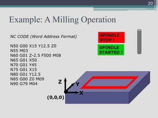
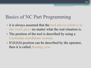
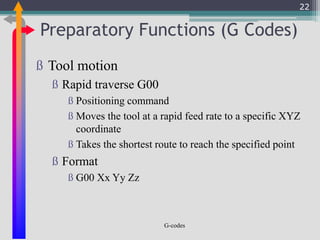
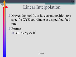

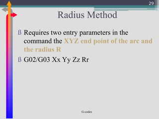
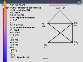
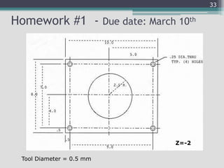
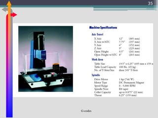
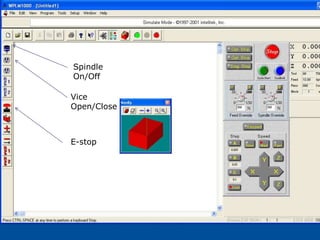

This document provides information on computer integrated manufacturing (CIM) and computer numerical control (CNC) machining. CIM aims to automate entire manufacturing plants under computer control, linking all processes digitally. It includes CAD/CAM for design and manufacturing, computer-aided process planning, and CNC machine tools controlled by computers. The core of CIM is CAD/CAM, which reduces cycle times. CAD/CAM provides design, planning, and fabrication capabilities. CNC machining uses G-codes and preparatory functions to precisely control tool movements and machine parts. CNC offers advantages like reduced time, costs, and errors compared to conventional machining.