Download as PDF, PPTX

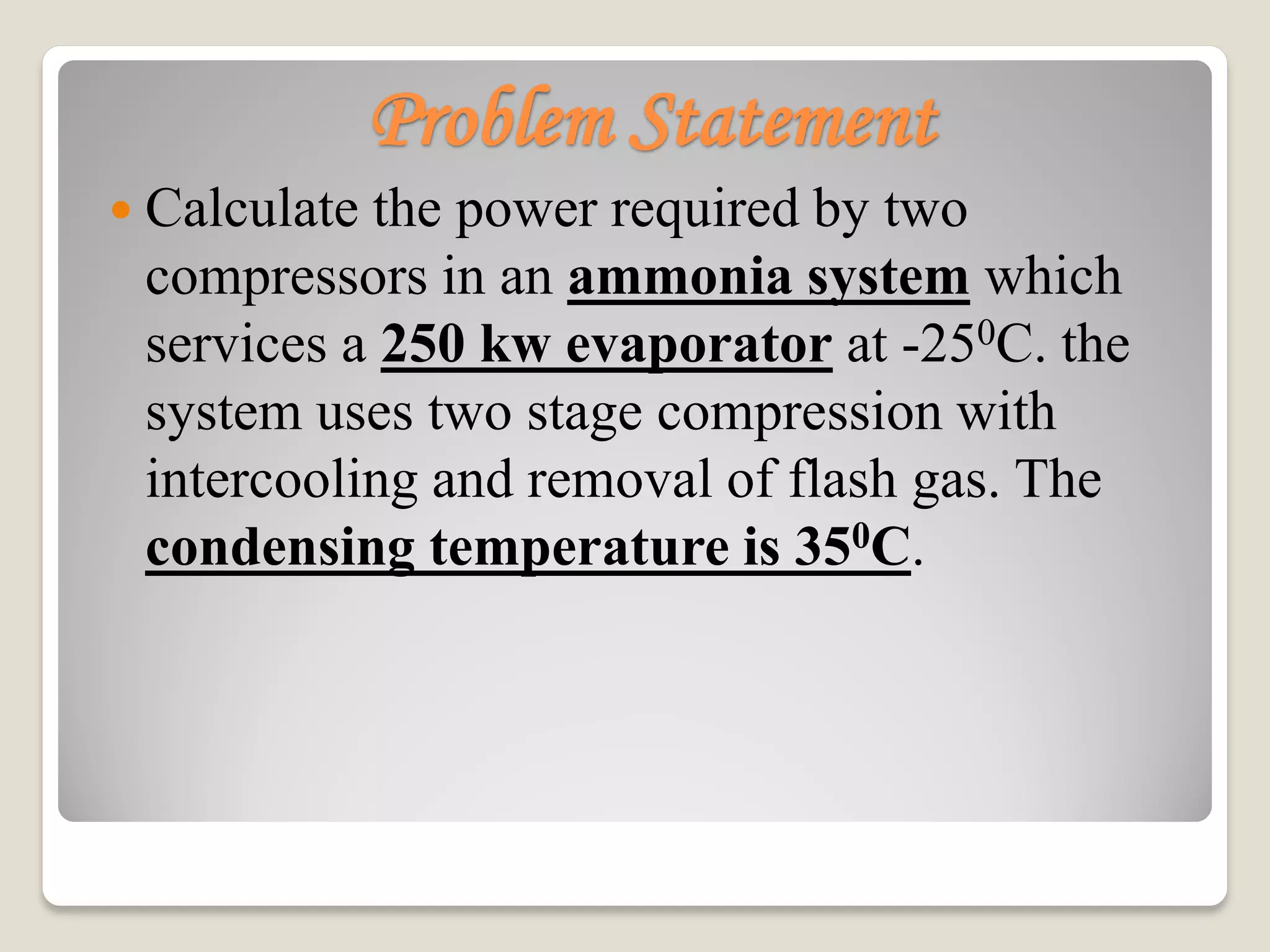
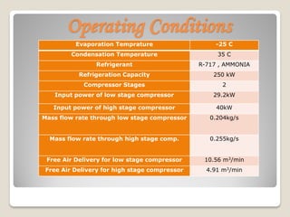
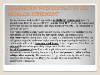
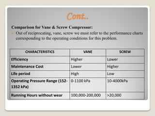
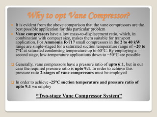
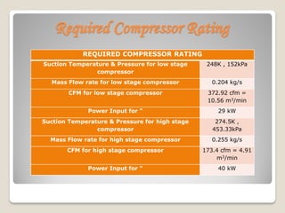
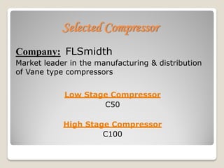
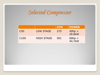

The document calculates the power requirements for two compressors in an ammonia refrigeration system servicing a 250 kW evaporator at -25°C. It concludes that vane compressors are the most suitable option, outlining their efficiency, maintenance costs, and required specifications for a two-stage system. Selected models and specifications for the low and high-stage compressors are provided, alongside justifications for excluding other compressor types.


