coding and wiring dht11 and ultrasonic hcsr04 arduino
•Download as DOCX, PDF•
0 likes•69 views

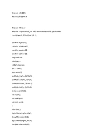
this is programming sensor dht11 and ultrasonic hcsr04. you can download the library 1. LiquidCrystalI2C 2. dht11 3. adafruit sensor master
Report
Share
Report
Share

Recommended
Atmega lcd programing_with_header_file
This document contains C code for initializing and controlling a 16x2 LCD display module connected to an AVR microcontroller. It defines macros for the LCD port and data direction register. Functions are defined to send command and data bytes to the LCD via the LCD port. An lcd_init() function initializes the LCD to 4-bit mode and clears the display. Other functions allow setting the cursor position, writing a string to the LCD, and clearing the display. The main() function demonstrates initializing the LCD, writing strings to different lines, waiting, and then clearing the display.
W8_2: Inside the UoS Educational Processor
In this unit we provide more details to the UoS educational, in particular it's implementation in VHDL.
Unit duration: 50mn.
License: LGPL 2.1
Dam gate open close lpc prog
This document contains C code for an ARM7-based flood alert system using an LCD display. It includes function definitions for initializing the LCD, writing data and instructions, setting the cursor position, printing strings, and generating delays. The main program loop continuously clears the display, prints status messages, and checks sensor input to play warning messages and indicate flood conditions or normal status on the LCD.
Zn task - defcon russia 20
The document describes a simulated hacking game scenario involving a compromised POS terminal infected with malware. It details the components of the botnet architecture including bot nodes, command and control infrastructure, and social media propagation. Diagrams show the network layout and communication channels. The document also examines the bot's components, capabilities, and protection mechanisms such as bytecode encryption and anti-debugging techniques. Hints are provided to help players progress in the game by bypassing defenses and achieving objectives over multiple days.
Advanced cfg bypass on adobe flash player 18 defcon russia 23
This document describes an advanced technique to bypass Control Flow Guard (CFG) protections on Adobe Flash Player 18 and Windows 8.1. It details how the researchers were able to generate indirect call instructions in just-in-time (JIT) compiled Flash code to redirect execution to controlled addresses, bypassing CFG. This was done by manipulating parameters passed between functions to influence the JIT compiler's code generation and produce the desired indirect call opcodes. The technique allowed full control-flow hijacking on the protected systems.
Lcd module interface with xilinx software using verilog
This document describes a design that interfaces an LCD display to an FPGA board. This allows the data displayed on the LCD to be flexible and configurable through the FPGA, rather than being static. The design implements a multi UART serial communication block with configurable baud rates to interface between the FPGA and LCD. The UART and LCD driver are developed in Verilog and can be integrated into the FPGA. As a proof of concept, the design displays "HELLO WORLD" on the LCD. The RTL code is synthesized and implemented on a Xilinx Spartan FPGA board with the LCD.
FPGA Tutorial - LCD Interface
The document describes interfacing an FPGA to an LCD 16x2 display. It includes a block diagram, pin descriptions, timing diagrams, LCD initialization procedures from the datasheet, and VHDL code to implement the LCD controller on the FPGA. The VHDL code uses a state machine and ROM-based model with an 8-bit data line to generate the LCD initialization sequence and display text on the LCD. Behavioral and post-route simulations are shown to verify the design works as intended.
CODING IN ARDUINO
The document describes code for an Arduino project that uses a PIR sensor and sonar sensors to detect humans. It includes code for an auto mode and manual mode, with the auto mode using sensors to control motors and the manual mode allowing control via radio signals. Functions are defined for the sensors, motors and radio communication.
Codigo fuente
This document contains code for displaying a matrix on an 8x8 LED display using a PIC microcontroller. It includes function definitions to send individual columns of data, send a vector to the display by forming it into a matrix, and send the entire matrix to the display. The main function initializes ports, declares some global vectors, and calls the functions to continuously display one vector then clear the display.
Micro Assignment 2
The document contains several microcontroller programs written in C code to:
1. Generate a 1 kHz frequency using a CCP module.
2. Calculate the time period of a frequency using an external interrupt and CCP module.
3. Calculate the duty cycle of a pulse.
4. Increase and decrease the pulse width with buttons.
5. Turn an LED on and off with a 1 second delay using a timer.
Fpga creating counter with external clock
The document describes the design and implementation of a seven segment counter on an FPGA. It includes the implementation of a prescaler, debouncing circuit, binary coded decimal (BCD) counter, and seven segment decoder. The prescaler was initially generating a warning about excessive skew, which was resolved by adding a clock buffer to the prescaler output. The design components are instantiated and connected in the top level system counter entity.
Fpga creating counter with internal clock
This document describes a design for a counter seven segment display using an FPGA. The author implemented a counter component and a decoder component, then wired them together in a top-level systemSeg entity using port mapping. The counter counts from 0 to 9 and outputs a 4-bit binary coded decimal value. The decoder converts the 4-bit input to a 7-segment display output based on a case statement. The author notes that port mapping is useful for wiring components together in HDL and that designs need to be synchronous with a clock.
123
The document discusses Berkeley socket network programming in TCP. It covers how to create server and client sockets in TCP, including the socket(), bind(), listen(), accept(), and connect() functions. It also covers converting between host and network byte order, socket options like SO_REUSEADDR, and the TCP connection states including TIME_WAIT.
گزارش کار
1. A 32-bit single-cycle MIPS processor was implemented by coding each component in VHDL and connecting them together. The code was synthesized and a report showed a total memory usage of 270752 kilobytes.
2. To implement a 32-bit multi-cycle MIPS processor, changes were made to the single-cycle code including defining four registers between stages and connecting the input and output ports of corresponding components. Signals were defined to allow data transfer between register stages. The register files were then connected using port maps.
Example MVS Console Interface
This program demonstrates a simple console interface to call FTP2 in a batch environment, allowing the operator to retry a failed process. This is most useful for situations where receiving servers might be down for short periods of time and thus unable to receive a file transmission on the first attempt.
Linux seccomp(2) vs OpenBSD pledge(2)
seccomp is a computer security facility in the Linux kernel, pledge is a similar security facility in the OpenBSD kernel. In this presentation Giovanni Bechis will review the development story and progress of both kernel interfaces and will analyze the main differences. There will be some examples of implementations of security patches made for some important open source projects.
Metal detecting robot sketch
This document defines functions to control a servo motor and DC motors to move a robot forward, backward, left, and right. It uses an ultrasonic sensor to scan the area and detect obstacles, and directs the robot to turn right, back up and turn right, or turn left depending on where the obstacle is detected to avoid collisions. The robot moves forward and calls the scan function in a loop to continually check for obstacles as it moves.
[DSC] Introduction to Binary Exploitation
This event is part of our ongoing series about IT Security. In this session, Carl Svensson, a security professional working in the Google Offensive Security team, gives us an introduction to Binary Exploitation. Watch the recording at https://dscmunich.de/binexp
Arduino and Robotics
This document outlines the syllabus for an Arduino workshop that will cover basic concepts like inputs, outputs, and programming. It includes sections that explain how to use functions like pinMode(), digitalWrite(), analogRead(), and functions for using sensors like ultrasonic distance measurement. The document also covers using the Serial Monitor, LCD displays, and introduces concepts in robotics like sensing, thinking, planning and output. The overall workshop aims to teach participants how to get started with Arduino and touch on the concept of infinity through hands-on projects.
The Simple Scheduler in Embedded System @ OSDC.TW 2014
The document describes a simple scheduler module implemented in C for embedded systems. It breaks processes into small jobs represented by functions that are scheduled in a first-in, first-out queue without preemption. This allows embedding an operating system concept into simple systems using only functions and a ready queue. Interrupts can add jobs to the queue. The scheduler and example oscilloscope application demonstrate scheduling without process state using only callbacks.
ゆるふわコンピュータ (IPSJ-ONE2017)
The document discusses Twitter and GitHub accounts, an IPSJ conference, and hardware including an Intel Core i7, FPGA boards from Digilent and ScalableCore, and code snippets for C programs and hardware designs including for a convolutional neural network layer.
Using ARM Dev.Board in physical experimental instruments
This document discusses using ARM development boards for physical experimental instruments. It provides examples of the Raspberry Pi and STM32 microcontrollers, comparing their interfaces, development environments, and use in prototypes that require high-speed digital-to-analog and analog-to-digital conversion with Ethernet connectivity. Prototypes achieved update times of 5us or less while maintaining real-time data transfer capabilities. Future plans include higher resolution converters and combining STM and Raspberry Pi units for scalable real-time control.
Vm ware fuzzing - defcon russia 20
The document discusses using virtual machine techniques like GuestRPC and Backdoor I/O to conduct virtual denial of service attacks. It describes fuzzing the GuestRPC interface to discover bugs in systems like HGFS that could be exploited to cause memory leaks or crashes on the host machine. While vendors issue fixes, it notes that fully preventing abuse of these virtual machine behaviors is difficult and some techniques remain unfixed. It concludes with questions about using these kinds of attacks to bypass security systems on virtual machines.
Pledge in OpenBSD
Pledge is a new mitigation technique available in the OpenBSD operating system.
It is used to disable system calls a process is not allowed to call.
Lcd n PIC16F
This document contains code for interfacing with an LCD display using a Hitachi HD44780 controller in 4-bit mode. It includes function definitions for initializing the LCD, writing data, clearing the screen, writing strings and characters to specific positions on the LCD. The main function calls lcd_init() to initialize the LCD, then uses printf() to write strings at different positions on the LCD to display text for testing the LCD interface.
REPORT
This project report describes a treadmill simulation project using an 8052 microcontroller. The hardware components included an 8052 microcontroller, LCD display, numeric keypad, DC motor, and other components. The code was written to control the keypad, LCD display, motor and calculate calories burned based on speed, time, weight and gender of the user. The project was simulated using Proteus and results matched the expected functionality.
Embedded JavaScript
This document discusses using JavaScript for embedded programming on microcontrollers. It introduces Espruino, which allows programming microcontrollers using JavaScript. Espruino provides inexpensive hardware with peripherals and libraries, making it suitable for hobbyists and prototyping. In contrast to Arduino, Espruino includes a debugger. The document demonstrates examples of using Espruino to read temperature and humidity sensors and expose sensor data over Bluetooth Low Energy. It encourages exploring Espruino and related projects like Tessel and Neonious for embedded JavaScript development.
Microcontroladores: programas de CCS Compiler.docx
This document contains programs for a PIC microcontroller that implement various functions including:
1) Scanning a 4x4 keypad and displaying the pressed number on a 7-segment display.
2) Using an ADC to read pressure sensor data and transmit it via RS-232.
3) Transmitting and receiving data between two PICs via RS-232.
4) Blinking LEDs on ports and driving a buzzer.
5) Reading an ADC and displaying the value on an LCD.
6) Implementing a timer and counting seconds on an LCD.
7) Using I2C to communicate with a device.
8) Scanning a keypad and unlock
Distance measurement using Ultrasonic sensor on Arduino Uno
The PPT contains a small presentation for mini-project that can be made to measurement distance using Ultrasonic sensor on Arduino Uno
More Related Content
What's hot
Codigo fuente
This document contains code for displaying a matrix on an 8x8 LED display using a PIC microcontroller. It includes function definitions to send individual columns of data, send a vector to the display by forming it into a matrix, and send the entire matrix to the display. The main function initializes ports, declares some global vectors, and calls the functions to continuously display one vector then clear the display.
Micro Assignment 2
The document contains several microcontroller programs written in C code to:
1. Generate a 1 kHz frequency using a CCP module.
2. Calculate the time period of a frequency using an external interrupt and CCP module.
3. Calculate the duty cycle of a pulse.
4. Increase and decrease the pulse width with buttons.
5. Turn an LED on and off with a 1 second delay using a timer.
Fpga creating counter with external clock
The document describes the design and implementation of a seven segment counter on an FPGA. It includes the implementation of a prescaler, debouncing circuit, binary coded decimal (BCD) counter, and seven segment decoder. The prescaler was initially generating a warning about excessive skew, which was resolved by adding a clock buffer to the prescaler output. The design components are instantiated and connected in the top level system counter entity.
Fpga creating counter with internal clock
This document describes a design for a counter seven segment display using an FPGA. The author implemented a counter component and a decoder component, then wired them together in a top-level systemSeg entity using port mapping. The counter counts from 0 to 9 and outputs a 4-bit binary coded decimal value. The decoder converts the 4-bit input to a 7-segment display output based on a case statement. The author notes that port mapping is useful for wiring components together in HDL and that designs need to be synchronous with a clock.
123
The document discusses Berkeley socket network programming in TCP. It covers how to create server and client sockets in TCP, including the socket(), bind(), listen(), accept(), and connect() functions. It also covers converting between host and network byte order, socket options like SO_REUSEADDR, and the TCP connection states including TIME_WAIT.
گزارش کار
1. A 32-bit single-cycle MIPS processor was implemented by coding each component in VHDL and connecting them together. The code was synthesized and a report showed a total memory usage of 270752 kilobytes.
2. To implement a 32-bit multi-cycle MIPS processor, changes were made to the single-cycle code including defining four registers between stages and connecting the input and output ports of corresponding components. Signals were defined to allow data transfer between register stages. The register files were then connected using port maps.
Example MVS Console Interface
This program demonstrates a simple console interface to call FTP2 in a batch environment, allowing the operator to retry a failed process. This is most useful for situations where receiving servers might be down for short periods of time and thus unable to receive a file transmission on the first attempt.
Linux seccomp(2) vs OpenBSD pledge(2)
seccomp is a computer security facility in the Linux kernel, pledge is a similar security facility in the OpenBSD kernel. In this presentation Giovanni Bechis will review the development story and progress of both kernel interfaces and will analyze the main differences. There will be some examples of implementations of security patches made for some important open source projects.
Metal detecting robot sketch
This document defines functions to control a servo motor and DC motors to move a robot forward, backward, left, and right. It uses an ultrasonic sensor to scan the area and detect obstacles, and directs the robot to turn right, back up and turn right, or turn left depending on where the obstacle is detected to avoid collisions. The robot moves forward and calls the scan function in a loop to continually check for obstacles as it moves.
[DSC] Introduction to Binary Exploitation
This event is part of our ongoing series about IT Security. In this session, Carl Svensson, a security professional working in the Google Offensive Security team, gives us an introduction to Binary Exploitation. Watch the recording at https://dscmunich.de/binexp
Arduino and Robotics
This document outlines the syllabus for an Arduino workshop that will cover basic concepts like inputs, outputs, and programming. It includes sections that explain how to use functions like pinMode(), digitalWrite(), analogRead(), and functions for using sensors like ultrasonic distance measurement. The document also covers using the Serial Monitor, LCD displays, and introduces concepts in robotics like sensing, thinking, planning and output. The overall workshop aims to teach participants how to get started with Arduino and touch on the concept of infinity through hands-on projects.
The Simple Scheduler in Embedded System @ OSDC.TW 2014
The document describes a simple scheduler module implemented in C for embedded systems. It breaks processes into small jobs represented by functions that are scheduled in a first-in, first-out queue without preemption. This allows embedding an operating system concept into simple systems using only functions and a ready queue. Interrupts can add jobs to the queue. The scheduler and example oscilloscope application demonstrate scheduling without process state using only callbacks.
ゆるふわコンピュータ (IPSJ-ONE2017)
The document discusses Twitter and GitHub accounts, an IPSJ conference, and hardware including an Intel Core i7, FPGA boards from Digilent and ScalableCore, and code snippets for C programs and hardware designs including for a convolutional neural network layer.
Using ARM Dev.Board in physical experimental instruments
This document discusses using ARM development boards for physical experimental instruments. It provides examples of the Raspberry Pi and STM32 microcontrollers, comparing their interfaces, development environments, and use in prototypes that require high-speed digital-to-analog and analog-to-digital conversion with Ethernet connectivity. Prototypes achieved update times of 5us or less while maintaining real-time data transfer capabilities. Future plans include higher resolution converters and combining STM and Raspberry Pi units for scalable real-time control.
Vm ware fuzzing - defcon russia 20
The document discusses using virtual machine techniques like GuestRPC and Backdoor I/O to conduct virtual denial of service attacks. It describes fuzzing the GuestRPC interface to discover bugs in systems like HGFS that could be exploited to cause memory leaks or crashes on the host machine. While vendors issue fixes, it notes that fully preventing abuse of these virtual machine behaviors is difficult and some techniques remain unfixed. It concludes with questions about using these kinds of attacks to bypass security systems on virtual machines.
Pledge in OpenBSD
Pledge is a new mitigation technique available in the OpenBSD operating system.
It is used to disable system calls a process is not allowed to call.
Lcd n PIC16F
This document contains code for interfacing with an LCD display using a Hitachi HD44780 controller in 4-bit mode. It includes function definitions for initializing the LCD, writing data, clearing the screen, writing strings and characters to specific positions on the LCD. The main function calls lcd_init() to initialize the LCD, then uses printf() to write strings at different positions on the LCD to display text for testing the LCD interface.
REPORT
This project report describes a treadmill simulation project using an 8052 microcontroller. The hardware components included an 8052 microcontroller, LCD display, numeric keypad, DC motor, and other components. The code was written to control the keypad, LCD display, motor and calculate calories burned based on speed, time, weight and gender of the user. The project was simulated using Proteus and results matched the expected functionality.
Embedded JavaScript
This document discusses using JavaScript for embedded programming on microcontrollers. It introduces Espruino, which allows programming microcontrollers using JavaScript. Espruino provides inexpensive hardware with peripherals and libraries, making it suitable for hobbyists and prototyping. In contrast to Arduino, Espruino includes a debugger. The document demonstrates examples of using Espruino to read temperature and humidity sensors and expose sensor data over Bluetooth Low Energy. It encourages exploring Espruino and related projects like Tessel and Neonious for embedded JavaScript development.
What's hot (20)
The Simple Scheduler in Embedded System @ OSDC.TW 2014
The Simple Scheduler in Embedded System @ OSDC.TW 2014
Using ARM Dev.Board in physical experimental instruments
Using ARM Dev.Board in physical experimental instruments
Similar to coding and wiring dht11 and ultrasonic hcsr04 arduino
Microcontroladores: programas de CCS Compiler.docx
This document contains programs for a PIC microcontroller that implement various functions including:
1) Scanning a 4x4 keypad and displaying the pressed number on a 7-segment display.
2) Using an ADC to read pressure sensor data and transmit it via RS-232.
3) Transmitting and receiving data between two PICs via RS-232.
4) Blinking LEDs on ports and driving a buzzer.
5) Reading an ADC and displaying the value on an LCD.
6) Implementing a timer and counting seconds on an LCD.
7) Using I2C to communicate with a device.
8) Scanning a keypad and unlock
Distance measurement using Ultrasonic sensor on Arduino Uno
The PPT contains a small presentation for mini-project that can be made to measurement distance using Ultrasonic sensor on Arduino Uno
selected input/output - sensors and actuators
Selected Input/Output - Sensors & Actuators
LDR Laser Receiver, PIR Sensor, LM35, DHT11, Ultrasonic Sensor HC SR04
Local Input/Output with Processing.org
Arduino: Arduino lcd
The document provides code and instructions for three Arduino projects using an LCD screen:
1) A "Hello World" display that prints text to the LCD screen.
2) A weather station that reads temperature and humidity from a sensor and displays the readings.
3) An optional "Magic 8 Ball" project that displays random answers when shaken.
PIC and LCD
This document contains code for initializing and controlling a LCD display module connected to a PIC16F887 microcontroller. It defines macros for the LCD pins and functions for initializing the LCD, writing data, clearing the display, moving the cursor, and printing strings. The main program initializes the LCD, prints two strings to different rows, and loops continuously displaying them.
Gaztea Tech Robotica 2016
The document provides instructions for setting up an ESP8266 microcontroller to control appliances remotely via MQTT and radio frequency signals. It explains how to connect the ESP8266 to WiFi, set up an MQTT client, and subscribe to commands topics to control plugs by sending RF codes when messages are received. Code examples are given to demonstrate publishing sensor data to MQTT and handling incoming messages to trigger the RF transmitter as needed.
What will be quantization step size in numbers and in voltage for th.pdf
What will be quantization step size in numbers and in voltage for this Arduino Code? Using 5V
const int led1 = 2;
const int led2 = 3;
const int led3 = 4;
void setup() {
pinMode(led1, OUTPUT);
pinMode(led2, OUTPUT);
pinMode(led3, OUTPUT);
// initialize serial communication at 9600 bits per second:
Serial.begin(9600);
}
// the loop routine runs over and over again forever:
void loop() {
// read the input on analog pin 0:
int sensorValue = analogRead(A0);
int dataConv = sensorValue*(8.0/1024);
//write analog equvivalant data on led pins
switch(dataConv)
{
case 0: {
digitalWrite(led1,LOW);
digitalWrite(led2,LOW);
digitalWrite(led3,LOW);
break;
}
case 1: {
digitalWrite(led1,HIGH);
digitalWrite(led2,LOW);
digitalWrite(led3,LOW);
break;
}
case 2: {
digitalWrite(led1,LOW);
digitalWrite(led2,HIGH);
digitalWrite(led3,LOW);
break;
}
case 3: {
digitalWrite(led1,HIGH);
digitalWrite(led2,HIGH);
digitalWrite(led3,LOW);
break;
}
case 4: {
digitalWrite(led1,LOW);
digitalWrite(led2,LOW);
digitalWrite(led3,HIGH);
break;
}
case 5: {
digitalWrite(led1,HIGH);
digitalWrite(led2,LOW);
digitalWrite(led3,HIGH);
break;
}
case 6: {
digitalWrite(led1,LOW);
digitalWrite(led2,HIGH);
digitalWrite(led3,HIGH);
break;
}
case 7: {
digitalWrite(led1,HIGH);
digitalWrite(led2,HIGH);
digitalWrite(led3,HIGH);
break;
}
}
Serial.println(sensorValue); // print out the value you read:
Serial.println(dataConv);
delay(1000); // delay in between reads for stability
}
Solution
// Random LED Dots - from noise source
// Ed Nisley - KE4ANU - September 2015
//----------
// Pin assignments
const byte PIN_HEARTBEAT = 8; // DO - heartbeat LED
const byte PIN_SYNC = A3; // DO.
Temperature Sensor with LED matrix Display BY ►iRFAN QADOOS◄ 9
The document summarizes an Arduino final project to create a temperature sensor that displays readings on an 8x8 LED matrix. An Arduino uses two shift registers to control the rows and columns of the LED display. It reads the temperature from an LM335 sensor, converts it to a string, and scrolls the message across the display using interrupts and time-multiplexing of the rows and columns to refresh at 100Hz.
LCD_Example.pptx
The document provides instructions for using an LCD display with a PIC microcontroller. It describes connecting the LCD to the microcontroller in 4-bit mode to save pins. It includes the LCD initialization routine, functions for sending data and commands to the LCD, and positioning the cursor. In the main program, it reads analog sensor values, controls fan speed with PWM, and displays the values and fan speed on the LCD at different lines and positions on the screen.
Magnetic door lock using arduino
This document describes the design and implementation of a magnetic door lock system using an Arduino board. The system uses a keypad to enter a secret code, and unlocks a solenoid on the door when the correct code is entered. It provides status using LED lights. The system stores the code in EEPROM and can be programmed to a new code via the keypad. The document outlines the hardware components, circuit diagram, software code, and concludes with potential applications and extensions of the system.
How do I draw the Labview code for pneumatic cylinder(air pistion). .pdf
How do I draw the Labview code for pneumatic cylinder(air pistion). (Start with banana-plug>>
Pneumatic cylinder(air pistion) moves back and forward certain times or certain seconds>> end)
Solution
#include
#include
#include
#include
#include \"RTClib.h\"
#define LOG_INTERVAL 1 // milsec betweens entries
#define SYNC_INTERVAL 100
uint32_t syncTime =0;
RTC_DS1307 RTC; // Real Time Clock
// On the Ethernet Shield, CS is pin 4. Note that even if it\'s not
// used as the CS pin, the hardware CS pin (10 on most Arduino boards,
// 53 on the Mega) must be left as an output or the SD library
// functions will not work.
const int chipSelect = 10;
//switch inputs and variables
const int kPinReedSwitch1 = 22;
const int kPinReedSwitch2 = 24;
const int relayPin = 26;
int strokedown = 0;
int inc = 0;
int precountA =0;
int precountB = 0;
int count = 0;
int runcycles = 20;
int reset = 0;
int initial = 1;
int start =1;
int LinearPot1Pin = A0; // select the input pin for the potentiometer
float sensorValue = 0.0; // variable to store the value coming from the sensor
int MC_travel = 0;
int on =0;
//logging file
File logfile;
LiquidCrystal lcd(7, 8, 9, 10, 11, 12);
void error(char *str)
{
Serial.print(\"error: \");
Serial.println(str);
while(1);
}
void setup()
{
// Open serial communications and wait for port to open:
Serial.begin(9600);
while (!Serial) {
; // wait for serial port to connect. Needed for Leonardo only
}
// Input pins for Arduino
pinMode(kPinReedSwitch1, INPUT_PULLUP);
pinMode(kPinReedSwitch2, INPUT_PULLUP);
pinMode(relayPin, OUTPUT);
Serial.print(\"Initializing SD card...\");
// make sure that the default chip select pin is set to
// output, even if you don\'t use it:
pinMode(53, OUTPUT);
// see if the card is present and can be initialized:
if (!SD.begin(10,11,12,13)) {
Serial.println(\"Card failed, or not present\");
// don\'t do anything more:
return;
}
Serial.println(\"card initialized.\");
// creating a new file for data logger
char filename[] = \"LOGGER00.CSV\";
for (uint8_t i = 0; i < 100; i++){
filename[6] = i/10 + \'0\';
filename[7] = i%10 + \'0\';
if(! SD.exists(filename)){
logfile = SD.open(filename, FILE_WRITE);
break;
}
}
if (!logfile) {
error(\"couldnt create file\");
}
Serial.print(\"Logging to:\");
Serial.println(filename);
logfile.println(\"MC Travel\");
// LCD initialization
lcd.begin(20,4);
lcd.clear();
lcd.setCursor(0,0);
lcd.print(\"Count: \");
lcd.setCursor(0,1);
lcd.print(\"MC Travel: in\");
}
void loop()
{
for(int i = 1; i < 2; i++ )
//an initialization routine just to get cylinder to \"home\"
//although should never really be away from home
{
digitalWrite(relayPin, HIGH);
delay(200);
digitalWrite(relayPin, LOW);
delay (2000);
}
while( count <= runcycles){
if( start ==1 && digitalRead(kPinReedSwitch1)==HIGH){
digitalWrite(relayPin, HIGH);
}
else if (digitalRead(kPinReedSwitch1) == LOW)
// turns on relay when reed switch A is triggered
// Logic reversed because of pullup resistors
{
strokedown = 1;
precountA =1;
start=0;// .
Uart
The document describes a Universal Asynchronous Receiver Transmitter (UART) circuit. A UART allows a computer to communicate with external devices by transmitting serial data. It contains a receiver that takes in serial data and a transmitter that sends out serial data. A baud rate generator is used to synchronize the transmission and reception of bits. The document provides details on the UART components, data encoding, and includes VHDL code for a UART design.
code-nodemcu.docx
bhbfbf jbfb bef bbm bmnb bnmb nbef nqbnmbf bfnmbafb mbfmnb qbn bqnq bbnmb bq bqmn bnb mqbmn bqnbj hqjkh kh kjhjk hkjhqjh khjkh kh qjh jkqh jh jkqh kjqh kjh kjqhjk hjkqhrkjqhkqh kjh jkqhjkqh kqhkqh kqh jkh kjqh kjqhkj hkh khekj jkhkj hqkh kjqhrkjq qh kjhrj qhkjq hkq h kjqhr jq h hq jhqkj qj hkjhjkqhr jkqhrkj h qhr qjrhqjr
Tdm to vo ip 2
This document describes a hardware design that includes components like a codec clock, PLL, and packet memory. It maps these components, describes signal connections between them, and includes processes for transferring data between the memory and codec. The design takes in audio data at 2.048 MHz, converts it to 75 MHz using a PLL, stores it in packet memory, and outputs it to a codec. It handles transferring 160 bytes per packet across two memory banks.
Day1
Here is a program to count in binary using LEDs on pins D11, D12 and D13:
```
int ledPins[] = {11, 12, 13};
void setup() {
for(int i=0; i<3; i++) {
pinMode(ledPins[i], OUTPUT);
}
}
void loop() {
for(int i=0; i<8; i++) {
for(int j=0; j<3; j++) {
digitalWrite(ledPins[j], bitRead(i,j));
}
delay(1000);
}
}
```
This program:
-
Arduino
This code is controlling an access control system using an Arduino. It includes libraries for fingerprint scanning, camera, SD card, and NFC. It can unlock the door by matching a fingerprint, NFC tag, or both. When the door is opened, it takes a picture with the camera and saves it to an SD card. It puts the Arduino to sleep when the door is closed to save power.
131080111003 mci
This document describes how to interface an LCD display with an Atmega 32 microcontroller. It provides details on the pin descriptions of a 16x2 LCD, how to send commands and data to the LCD by selecting the appropriate registers, a code example in C to initialize and write text to the LCD, and screenshots of the code running in Proteus simulation software displaying "AVR 32" and "Atmega32" on the LCD. It also lists common LCD display commands.
Realization of an 8 bit pipelined microprocessor in verilog hdl
The International Institute for Science, Technology and Education (IISTE) Journals Call for paper http://www.iiste.org/Journals
Microcontroller Programming Assignment
The document contains 16 programs with code snippets to control various electronic components and devices using a microcontroller.
Program 1 turns an LED on and off with a 1 second delay using ports on a microcontroller.
Program 2 interfaces a 7-segment display with a microcontroller to display the numbers 0-9 by sending different byte patterns to the display ports.
Program 3 writes a program to count from 00 to FF in hexadecimal on PORT B of a microcontroller.
The remaining programs implement various functions like reading and sending data between ports, serial input/output, controlling motors and relays, interfacing with sensors, temperature control, and displaying values on an LCD screen by interfacing keypads and other external
8051 TIMER COUNTER SERIAL COMM. INTERUPT PROGRAMMING.pdf
Here is the code to interface an 8-bit DAC0808 with the 8051 microcontroller:
#include <reg51.h>
sbit DAC_CS = P1^0; // Chip Select pin
sbit DAC_R_W = P1^1; // Read/Write pin
void DAC_write(unsigned char data) {
DAC_CS = 0; // Select DAC chip
DAC_R_W = 1; // Write operation
P1 = data; // Send data byte
DAC_R_W = 0; // Unselect
DAC_CS = 1; // Deselect DAC chip
}
Similar to coding and wiring dht11 and ultrasonic hcsr04 arduino (20)
Microcontroladores: programas de CCS Compiler.docx
Microcontroladores: programas de CCS Compiler.docx
Distance measurement using Ultrasonic sensor on Arduino Uno
Distance measurement using Ultrasonic sensor on Arduino Uno
What will be quantization step size in numbers and in voltage for th.pdf
What will be quantization step size in numbers and in voltage for th.pdf
Temperature Sensor with LED matrix Display BY ►iRFAN QADOOS◄ 9
Temperature Sensor with LED matrix Display BY ►iRFAN QADOOS◄ 9
How do I draw the Labview code for pneumatic cylinder(air pistion). .pdf
How do I draw the Labview code for pneumatic cylinder(air pistion). .pdf
Realization of an 8 bit pipelined microprocessor in verilog hdl
Realization of an 8 bit pipelined microprocessor in verilog hdl
8051 TIMER COUNTER SERIAL COMM. INTERUPT PROGRAMMING.pdf
8051 TIMER COUNTER SERIAL COMM. INTERUPT PROGRAMMING.pdf
Recently uploaded
Andreas Schleicher presents PISA 2022 Volume III - Creative Thinking - 18 Jun...
Andreas Schleicher, Director of Education and Skills at the OECD presents at the launch of PISA 2022 Volume III - Creative Minds, Creative Schools on 18 June 2024.
مصحف القراءات العشر أعد أحرف الخلاف سمير بسيوني.pdf
مصحف أحرف الخلاف للقراء العشرةأعد أحرف الخلاف بالتلوين وصلا سمير بسيوني غفر الله له
HYPERTENSION - SLIDE SHARE PRESENTATION.
IT WILL BE HELPFULL FOR THE NUSING STUDENTS
IT FOCUSED ON MEDICAL MANAGEMENT AND NURSING MANAGEMENT.
HIGHLIGHTS ON HEALTH EDUCATION.
RHEOLOGY Physical pharmaceutics-II notes for B.pharm 4th sem students
Physical pharmaceutics notes for B.pharm students
BIOLOGY NATIONAL EXAMINATION COUNCIL (NECO) 2024 PRACTICAL MANUAL.pptx
Practical manual for National Examination Council, Nigeria.
Contains guides on answering questions on the specimens provided
Geography as a Discipline Chapter 1 __ Class 11 Geography NCERT _ Class Notes...
Geography as discipline
How Barcodes Can Be Leveraged Within Odoo 17
In this presentation, we will explore how barcodes can be leveraged within Odoo 17 to streamline our manufacturing processes. We will cover the configuration steps, how to utilize barcodes in different manufacturing scenarios, and the overall benefits of implementing this technology.
Benner "Expanding Pathways to Publishing Careers"
This presentation was provided by Rebecca Benner, Ph.D., of the American Society of Anesthesiologists, for the second session of NISO's 2024 Training Series "DEIA in the Scholarly Landscape." Session Two: 'Expanding Pathways to Publishing Careers,' was held June 13, 2024.
BÀI TẬP DẠY THÊM TIẾNG ANH LỚP 7 CẢ NĂM FRIENDS PLUS SÁCH CHÂN TRỜI SÁNG TẠO ...
BÀI TẬP DẠY THÊM TIẾNG ANH LỚP 7 CẢ NĂM FRIENDS PLUS SÁCH CHÂN TRỜI SÁNG TẠO ...Nguyen Thanh Tu Collection
https://app.box.com/s/qhtvq32h4ybf9t49ku85x0n3xl4jhr15Wound healing PPT
This document provides an overview of wound healing, its functions, stages, mechanisms, factors affecting it, and complications.
A wound is a break in the integrity of the skin or tissues, which may be associated with disruption of the structure and function.
Healing is the body’s response to injury in an attempt to restore normal structure and functions.
Healing can occur in two ways: Regeneration and Repair
There are 4 phases of wound healing: hemostasis, inflammation, proliferation, and remodeling. This document also describes the mechanism of wound healing. Factors that affect healing include infection, uncontrolled diabetes, poor nutrition, age, anemia, the presence of foreign bodies, etc.
Complications of wound healing like infection, hyperpigmentation of scar, contractures, and keloid formation.
Recently uploaded (20)
Andreas Schleicher presents PISA 2022 Volume III - Creative Thinking - 18 Jun...
Andreas Schleicher presents PISA 2022 Volume III - Creative Thinking - 18 Jun...
مصحف القراءات العشر أعد أحرف الخلاف سمير بسيوني.pdf
مصحف القراءات العشر أعد أحرف الخلاف سمير بسيوني.pdf
RHEOLOGY Physical pharmaceutics-II notes for B.pharm 4th sem students
RHEOLOGY Physical pharmaceutics-II notes for B.pharm 4th sem students
BIOLOGY NATIONAL EXAMINATION COUNCIL (NECO) 2024 PRACTICAL MANUAL.pptx
BIOLOGY NATIONAL EXAMINATION COUNCIL (NECO) 2024 PRACTICAL MANUAL.pptx
REASIGNACION 2024 UGEL CHUPACA 2024 UGEL CHUPACA.pdf
REASIGNACION 2024 UGEL CHUPACA 2024 UGEL CHUPACA.pdf
spot a liar (Haiqa 146).pptx Technical writhing and presentation skills
spot a liar (Haiqa 146).pptx Technical writhing and presentation skills
Geography as a Discipline Chapter 1 __ Class 11 Geography NCERT _ Class Notes...
Geography as a Discipline Chapter 1 __ Class 11 Geography NCERT _ Class Notes...
BÀI TẬP DẠY THÊM TIẾNG ANH LỚP 7 CẢ NĂM FRIENDS PLUS SÁCH CHÂN TRỜI SÁNG TẠO ...
BÀI TẬP DẠY THÊM TIẾNG ANH LỚP 7 CẢ NĂM FRIENDS PLUS SÁCH CHÂN TRỜI SÁNG TẠO ...
coding and wiring dht11 and ultrasonic hcsr04 arduino
- 1. #include <dht11.h> #define DHT11PIN 4 #include <Wire.h> #include <LiquidCrystal_I2C.h>//includesthe LiquidCrystal Library LiquidCrystal_I2Clcd(0x3F,16,2); const inttrigPin= 9; const intechoPin=10; const intbuzzer= 11; const intledPin=13; longduration; intdistance; intSafedistance; dht11 DHT11; voidsetup() { pinMode(trigPin,OUTPUT); pinMode(echoPin,INPUT); pinMode(buzzer,OUTPUT); pinMode(ledPin,OUTPUT); Serial.begin(9600); lcd.begin(); lcd.backlight(); lcd.blink_on() ; } voidloop() { digitalWrite(trigPin,LOW); delayMicroseconds(2); digitalWrite(trigPin,HIGH); delayMicroseconds(10);
- 2. digitalWrite(trigPin,LOW); duration= pulseIn(echoPin,HIGH); distance=duration*0.034/2; Safedistance =distance; if (Safedistance <=10 ) { digitalWrite(buzzer,HIGH); digitalWrite(ledPin,HIGH); } else{ digitalWrite(buzzer,LOW); digitalWrite(ledPin,LOW); } lcd.print("cm");//Printsstring"Distance"onthe LCD lcd.setCursor(0,0); lcd.print("Distance:"); lcd.print(distance); lcd.print("cm"); Serial.print("Distance:"); Serial.println(distance); intchk = DHT11.read(DHT11PIN); lcd.setCursor(0,1); lcd.print("Temperature:"); lcd.print((float)DHT11.temperature,2); Serial.print("Temperature (C):"); Serial.println((float)DHT11.temperature,2); delay(1000); }