Realization of an 8 bit pipelined microprocessor in verilog hdl
•
1 like•834 views

The International Institute for Science, Technology and Education (IISTE) Journals Call for paper http://www.iiste.org/Journals
![Computer Engineering and Intelligent Systems www.iiste.org
ISSN 2222-1719 (Paper) ISSN 2222-2863 (Online)
Vol 3, No.7, 2012
4)Temporary address storage: ad - 6 bits (6 LSBs of AR)
5)Memory check register: memocheck -1 bit (for register reference and memory reference istructions)
6)Current state register: current_state – 2 bits (to check the present state- fetch/decode/execute/store)
7)Next state register: next_state- 1 bit (to hold the value of next operation to be carried out-
fetch/decode/execute/return)
8)OPcode register: opcode – 3 bits
9)Instruct register: instruct -4 bits (in case instruction type is arithmetic/logical then this specifies type of
arithmetic/logical op to be carried out)
10)Registers RA,RB,rstore - 4 bits (to hold the address of source and destination registers respectively)
11)Temporary register: W- 8 bits (to hold the value of the end result of any arithmetic/ logical operation and incase of
data MOV operation it holds the immediate value of the data to be transferred)
3.Instruction Format:
1 bit 3 bits 4 bits 4 bits 4 bits
I Opcode Instruct RA(index) RB(index)
I : 1- Memory reference
0-Register reference
Opcode: operational code which tells us what type of operation is to be carried out on the data present at source
registers ,given by the index in RA RB. Opcode list:
000 - HLT: The cpu goes into an infinite loop terminating the program
001 - MVI: Move immediate value to destination register register(indicated by rstore), {RA,RB} is the 8-bit
concatenated word used as immediate data, rstore: address of destination register
000 (I=1) - STA: store contents of R0 (virtual accumulator) in the memory address given by ad;
001 (I=1) - LDA: load the contents of memory specified by ad into the accumulator (R0)
010 (I=1) - JMP: jump to the location specified by 6 bits in ad
010 – operation: opcode for all arithmetic /logical instructions further classified by 4 bits instruct field
MOV=0000; Move Contents Of Register[RB] To Register[RA]
ADD=0001; Add Contents Of Register[RB] with Contents Of Register[RA] & save result in R[A]
ADC=0010; ADD With Carry, Add contents of register[RB] with contents Of Register[RA] & save result In R[A]
SBB=0011; Subtract With Borrow
SUB=0100; Subtract contents of Register[RB] with contents of Register[RA] & save result in R[A]
INC=0110;Increment contents of Register[RA] & save result in R[A]
DEC=0111; Decrement contents of Register[RA] & save result in R[A]
AND=1001;Logically AND contents of Register[RB] with contents of Register[RA] & save result in R[A]
OR=1010; Logically OR contents of Register[RB] with contents of Register[RA] & save result in R[A]
XOR=1011; Logically XOR contents of Register[RB] with contents of Register[RA] & save result in R[A]
CMP=1000; Complement contents of Register[RA]
SHR=1100; Shift right contents of Register[RA] by 1 bit
SHL=1101; Shift left contents of Register[RA] by 1 bit
4.Program Code
module micropipeline(clk,rst); reg [0:7] mem [0:255];
input clk; reg memocheck;
input rst; reg [0:1] current_state; //stages
reg [0:3]PC; reg [0:1] next_state; //for keeping track
reg [0:15] imem [0:15]; //instruction memory reg [0:11] AR; //Address register
reg [0:15] IR; // instruction register reg [0:2] opcode;
reg [0:7] datareg; //data register reg [0:3] instruct;
reg [0:15] IRW; reg [0:3] RA,RB,rstore;
156](data:image/gif;base64,R0lGODlhAQABAIAAAAAAAP///yH5BAEAAAAALAAAAAABAAEAAAIBRAA7)
Recommended
More Related Content
What's hot
What's hot (20)
Similar to Realization of an 8 bit pipelined microprocessor in verilog hdl
Similar to Realization of an 8 bit pipelined microprocessor in verilog hdl (20)
More from Alexander Decker
More from Alexander Decker (20)
Recently uploaded
Recently uploaded (20)
Realization of an 8 bit pipelined microprocessor in verilog hdl
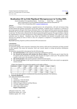
- 1. Computer Engineering and Intelligent Systems www.iiste.org ISSN 2222-1719 (Paper) ISSN 2222-2863 (Online) Vol 3, No.7, 2012 Realization Of An 8-bit Pipelined Microprocessor in Verilog HDL Jayant Chowdhary*(Corresponding Author) Vivek Garg Tushar Negi Shreya Jain Delhi Technological University,Shahbad Daulatpur,Main Bawana Road,Delhi-42 *Email of the corresponding author: jayantc11@gmail.com Abstract Pipelining is a technique of decomposing a sequential process into sub-operations, with each sub process being divided segment that operates concurrently with all other segments. A pipeline may be visualized as a collection of processing segments through which binary information flows. Each segment performs partial processing segments dictated by the way the task is partitioned. The result obtained in one segment is transferred to subsequent segments in each step. The final result is obtained after the data has passed through all segments.This paper develops a code for the implementation of an 8-Bit microprocessor which implements instruction pipelining. After synthesis, an FPGA realization may be obtained . Simulation using Xilinx and ModelSim also produces favourable results which showcase the speedup (in terms of time) to carry out a program as compared to a non-pipelined version of this microprocessor. Keywords:Pipelining, Segments,sysnthesis,realization,FPGA,microprocessor 1.Introduction Instruction pipelining An instruction pipeline reads consecutive instructions from memory while previous instructions are being executed in other segments. This causes the instruction ‘fetch’ and ‘execute’ phases to overlap and perform simultaneous operations. An instruction can generally be decomposed into the following steps: 1. FI- Fetch instruction: In this segment an instruction is fetched from memory. 2. DA- Decode the instruction and calculate the effective address: This instruction gets its input from the FI segment and the instruction is decoded. This step does not require a clock cycle. The operation which requires a clock cycle is the calculation of effective address. 3. FO- Fetch operand: In this step the operand is fetched from the memory. 4. EX- Execute and store: In this step the instruction is executed and the result is also stored in an appropriate memory location. A Space time diagram for an instruction pipeline can be made as follows: Instruction Step1 Step2 Step3 Step4 Step5 Step6 Step7 1 FI DA FO EX 2 FI DA FO EX 3 FI DA FO EX 4 FI DA FO EX As we can see each segment is simultaneously busy processing some part of an instruction. 2. Processor Realization CPU ORGANIZATION AND LAYOUT : 1) 8 bit cpu 2) Architecture: VON NEUMAN 3) Behavioural modelling only 4) Different Program Memory and Data Memory 5) 16 words of Program memory 6) 4096 words of data memory Register Organization: 1)Program Counter: PC – 6 bits 2)Instruction register: IR - 16 bits 3)Address register: AR - 12 bits 155
- 2. Computer Engineering and Intelligent Systems www.iiste.org ISSN 2222-1719 (Paper) ISSN 2222-2863 (Online) Vol 3, No.7, 2012 4)Temporary address storage: ad - 6 bits (6 LSBs of AR) 5)Memory check register: memocheck -1 bit (for register reference and memory reference istructions) 6)Current state register: current_state – 2 bits (to check the present state- fetch/decode/execute/store) 7)Next state register: next_state- 1 bit (to hold the value of next operation to be carried out- fetch/decode/execute/return) 8)OPcode register: opcode – 3 bits 9)Instruct register: instruct -4 bits (in case instruction type is arithmetic/logical then this specifies type of arithmetic/logical op to be carried out) 10)Registers RA,RB,rstore - 4 bits (to hold the address of source and destination registers respectively) 11)Temporary register: W- 8 bits (to hold the value of the end result of any arithmetic/ logical operation and incase of data MOV operation it holds the immediate value of the data to be transferred) 3.Instruction Format: 1 bit 3 bits 4 bits 4 bits 4 bits I Opcode Instruct RA(index) RB(index) I : 1- Memory reference 0-Register reference Opcode: operational code which tells us what type of operation is to be carried out on the data present at source registers ,given by the index in RA RB. Opcode list: 000 - HLT: The cpu goes into an infinite loop terminating the program 001 - MVI: Move immediate value to destination register register(indicated by rstore), {RA,RB} is the 8-bit concatenated word used as immediate data, rstore: address of destination register 000 (I=1) - STA: store contents of R0 (virtual accumulator) in the memory address given by ad; 001 (I=1) - LDA: load the contents of memory specified by ad into the accumulator (R0) 010 (I=1) - JMP: jump to the location specified by 6 bits in ad 010 – operation: opcode for all arithmetic /logical instructions further classified by 4 bits instruct field MOV=0000; Move Contents Of Register[RB] To Register[RA] ADD=0001; Add Contents Of Register[RB] with Contents Of Register[RA] & save result in R[A] ADC=0010; ADD With Carry, Add contents of register[RB] with contents Of Register[RA] & save result In R[A] SBB=0011; Subtract With Borrow SUB=0100; Subtract contents of Register[RB] with contents of Register[RA] & save result in R[A] INC=0110;Increment contents of Register[RA] & save result in R[A] DEC=0111; Decrement contents of Register[RA] & save result in R[A] AND=1001;Logically AND contents of Register[RB] with contents of Register[RA] & save result in R[A] OR=1010; Logically OR contents of Register[RB] with contents of Register[RA] & save result in R[A] XOR=1011; Logically XOR contents of Register[RB] with contents of Register[RA] & save result in R[A] CMP=1000; Complement contents of Register[RA] SHR=1100; Shift right contents of Register[RA] by 1 bit SHL=1101; Shift left contents of Register[RA] by 1 bit 4.Program Code module micropipeline(clk,rst); reg [0:7] mem [0:255]; input clk; reg memocheck; input rst; reg [0:1] current_state; //stages reg [0:3]PC; reg [0:1] next_state; //for keeping track reg [0:15] imem [0:15]; //instruction memory reg [0:11] AR; //Address register reg [0:15] IR; // instruction register reg [0:2] opcode; reg [0:7] datareg; //data register reg [0:3] instruct; reg [0:15] IRW; reg [0:3] RA,RB,rstore; 156
- 3. Computer Engineering and Intelligent Systems www.iiste.org ISSN 2222-1719 (Paper) ISSN 2222-2863 (Online) Vol 3, No.7, 2012 reg [0:7] regfile [0:15]; //16 register(R0-R7) execute<=1'b0; reg [0:7] W; //temporary register store<=1'b0; reg [0:2] count; sta<=1'b0; reg fetch,decode,execute,store; halt<=1'b0; reg [0:100]TR; end reg moveimm,movein,operation,sta,halt,halt1; else reg loadmemory,memorystore; begin reg load; if(store) wire carry; begin wire [0:7] temp; if(loadmemory&memorystore) reg carry1; begin reg [0:7] tink; regfile[rstore]<=W; reg car; end initial if(halt1) begin begin PC=0; fetch<=#1 1'b0; TR=0; decode<=#1 1'b0; fetch=1; execute<=#1 1'b0; decode=0; store<=#1 1'b0; execute=0; end store=0; end moveimm=0; if(execute) movein=0; begin operation=0; if(halt) halt=0; begin sta=0; halt1<=1'b1; loadmemory=1; end memorystore=1; load=0; if(moveimm) next_state=4'b1000; begin halt1=0; W<=IRW[8:15]; IRW=0; rstore<=IRW[4:7]; datareg[0]=0; moveimm<=1'b0; imem[0]={16'b0001000111001111}; end imem[1]={16'b0001001011011000}; if(movein) imem[2]={16'b0011000000010010}; begin imem[4]={16'b0000000000000000}; W<=datareg[IRW[12:15]]; imem[3]={16'b0000000000000000}; rstore<=IRW[8:11]; imem[5]={16'b0000000000000000}; movein<=1'b0; imem[6]={16'b0000000000000000}; end imem[7]={16'b0000000000000000}; if(operation) end begin always@(clk or rst) case(IRW[4:7]) begin 4'b0000: begin TR<=TR+1; W<=regfile[RA]+regfile[RB]; if(rst) end begin PC<=0; 4'b0001: begin TR<=0; fetch<=1'b1; W<=regfile[RA]+regfile[RB]+1; decode<=1'b0; end 157
- 4. Computer Engineering and Intelligent Systems www.iiste.org ISSN 2222-1719 (Paper) ISSN 2222-2863 (Online) Vol 3, No.7, 2012 load<=1'b0; 4’b0010: begin end W<=regfile[RA]-regfile[RB]-1; store<=1'b1; end end if(decode) 4'b0011:begin begin W<=regfile[RA]-regfile[RB]; IRW<=IR; end case(IR[0]) 0:begin 4'b0100: begin case(IR[1:3]) W<=regfile[RA]+1; 3'b000: begin end halt<=1'b1; end 4'b0101: begin 3'b001: W<=regfile[RA]-1; begin end moveimm<=1'b1; 4'b0110: begin end //the instruction is mvi W<=regfile[RB]; 3'b010: begin end movein<=1'b1; end 4'b1000: begin 3'b011:begin operation<=1; RA<=IR[8:11]; W<=regfile[RA]®file[RB]; RB<=IR[12:15]; end end 3'b100:begin 4'b1001: begin sta<=1'b1; W<=regfile[RA]|regfile[RB];end end 4'b1010: begin default:begin W<=regfile[RA]^regfile[RB]; end end endcase end 4'b1011: begin 1:begin W<=regfile[RA]; // has to include ~ load<=1'b1; End end endcase endcase // alu operation execute<=1'b1; rstore<=4'b0000; end if(count==2'b00) if(fetch) operation<=1'b0; begin end IR<=imem[PC]; if(sta) PC<=PC+1; begin decode<=1'b1; memorystore<=1'b0; end mem[IRW[8:15]]<=regfile[4'b0000]; end sta<=1'b0; if((IRW[4:7]==IR[8:11]|IRW[4:7]==IR[12:15])&IR[1: end 3]==3'b011) if(load) begin begin count<=2'b01; loadmemory<=1'b0; fetch<=#2 1'b0; regfile[4'b0000]<=mem[IRW[8:15]]; decode<=#2 1'b0; 158
- 5. Computer Engineering and Intelligent Systems www.iiste.org ISSN 2222-1719 (Paper) ISSN 2222-2863 (Online) Vol 3, No.7, 2012 end begin if(count==2'b01) count<=2'b00; begin fetch<=1'b1; count<=2'b10; decode<=1'b1; execute<=1'b0; end end end if(count==2'b10) endmodule 5.Results The following was the result of synthesis of the code on Xilinx and on comparing the timing diagram with that of a non-pipelined microprocessor running the same program we find that there is a considerable speedup of 125ps.The synthesis and timing diagrams of pipelined and non pipelined microprocessors are shown below: 159
- 6. Computer Engineering and Intelligent Systems www.iiste.org ISSN 2222-1719 (Paper) ISSN 2222-2863 (Online) Vol 3, No.7, 2012 Given above is the timing diagram of a non pipelined microprocessor built on specs to the pipelined one. A 4 instruction program takes 201 ps as shown to get executed. Given below is the timing diagram of the same program using the pipelined microprocessor presented in this paper. It can be seen the program execution time has reduced considerably to 76ps. 160
- 7. Computer Engineering and Intelligent Systems www.iiste.org ISSN 2222-1719 (Paper) ISSN 2222-2863 (Online) Vol 3, No.7, 2012 5.Conclusion This paper presents a basic pipelined microprocessor which has been written in Verilog HDL. This is simulation is unconventional in a way such that it showcases the beauty which goes into implementing pipelining of instructions in a microprocessor without going into too many complexities of the same.Moreover,this paper may be very effectively used as a tool in the field of education to introduce students to computer simulations of microprocessors. Students will definitely benefit from building upon this. The purpose of implementing an efficient microprocessor who’s working and intricacies are easy to understand has been successfully achieved. 6.Acknowledgments We would like to thank Mr. Kunwar Singh (Associate Professor,Department of Electrical Engineering,Delhi Technological University) and Dr.Suman Bhowmick(Associate Professor,Department of Electrical Engineering,Delhi Technological University) who never ceased in providing their valuable guidance till this project was completed. References 1. Verilog HDL (2nd Edition),Samir Palnitkar 2. Computer System Architecture (3rd Edition) M Morris Mano,Prentice Hall (1993) 3. Computer Systems Organization and Architecture ,John D. Carpinelli 4. Ronald, J. Tocci, Widmer, N. Moss, G. (1998), “Digital Systems Principles and Application”, Prentice-Hall 5. International Inc., New Jersey, 182-341. 6. Digital Design and Verilog HDL Fundamentals ,Joseph Canavagh,CRC Press(1st Edition 2008) 7. Verilog for Digital Design Frank Vahid , Roman Lysecky ,Wiley Digital Design (4th Edition)M.Morris Mano, Prentice Hall; 4 edition (December 25, 2006) 161
- 8. This academic article was published by The International Institute for Science, Technology and Education (IISTE). The IISTE is a pioneer in the Open Access Publishing service based in the U.S. and Europe. The aim of the institute is Accelerating Global Knowledge Sharing. More information about the publisher can be found in the IISTE’s homepage: http://www.iiste.org The IISTE is currently hosting more than 30 peer-reviewed academic journals and collaborating with academic institutions around the world. Prospective authors of IISTE journals can find the submission instruction on the following page: http://www.iiste.org/Journals/ The IISTE editorial team promises to the review and publish all the qualified submissions in a fast manner. All the journals articles are available online to the readers all over the world without financial, legal, or technical barriers other than those inseparable from gaining access to the internet itself. Printed version of the journals is also available upon request of readers and authors. IISTE Knowledge Sharing Partners EBSCO, Index Copernicus, Ulrich's Periodicals Directory, JournalTOCS, PKP Open Archives Harvester, Bielefeld Academic Search Engine, Elektronische Zeitschriftenbibliothek EZB, Open J-Gate, OCLC WorldCat, Universe Digtial Library , NewJour, Google Scholar