Microcontroladores: programas de CCS Compiler.docx
•Download as DOCX, PDF•
0 likes•94 views

This document contains programs for a PIC microcontroller that implement various functions including: 1) Scanning a 4x4 keypad and displaying the pressed number on a 7-segment display. 2) Using an ADC to read pressure sensor data and transmit it via RS-232. 3) Transmitting and receiving data between two PICs via RS-232. 4) Blinking LEDs on ports and driving a buzzer. 5) Reading an ADC and displaying the value on an LCD. 6) Implementing a timer and counting seconds on an LCD. 7) Using I2C to communicate with a device. 8) Scanning a keypad and unlock

Recommended
More Related Content
Similar to Microcontroladores: programas de CCS Compiler.docx
Similar to Microcontroladores: programas de CCS Compiler.docx (20)
More from SANTIAGO PABLO ALBERTO
More from SANTIAGO PABLO ALBERTO (20)
Recently uploaded
Recently uploaded (20)
Microcontroladores: programas de CCS Compiler.docx
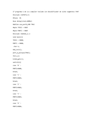
- 1. 1° programa 1 de ccs compiler teclado con decodificador de siete segmentos 7447 #include <16f877a.h> #fuses HS #use delay(clock=20MHz) #define use_portb_KBD TRUE #byte TRISC = 0X87 #byte PORTC = 0X07 #include <kbd4x4_1.c> void main(){ TRISC = 0X00; PORTC = 0X00; char k; kbd_init(); port_b_pullups(TRUE); for(;;){ k=kbd_getc(); switch(k){ case '0' : PORTC=0X00; break; case '1' : PORTC=0X01; break; case '2' : PORTC=0X02; break; case '3' : PORTC=0X03; break; case '4' : PORTC=0X04;
- 2. break; case '5' : PORTC=0X05; break; case '6' : PORTC=0X06; break; case '7' : PORTC=0X07; break; case '8' : PORTC=0X08; break; case '9' : PORTC=0X09; break; case '*' : PORTC=0X0F; break; } } }
- 3. 2° programa de ccs compiler utilizar la medición de sensor de presión con rs232 #include <16F877A.h> #device adc=10 #fuses HS #use delay(clock=20MHz) #use rs232(baud=9600, xmit=pin_c6, rcv=pin_c7, parity=N, bits=8) int16 x; float error, voltaje, KPa, Atm; void main() { setup_adc(ADC_CLOCK_INTERNAL); setup_adc_ports(AN0); set_adc_channel(0); while(true){ x=read_adc(); voltaje = 5.0*x/1024.0; KPa=(voltaje+0.475)/0.045; error=KPa-1.0; printf("presion: %5.2frnn", error); delay_ms(1000); Atm=0.0098692*KPa; printf("Atmosfera: %4.2frnn", Atm); delay_ms(1000); } }
- 4. 3° progr tx #include "16f877a.h" #fuses HS,NOWDT,NOPROTECT,NOLVP #use delay(clock=20 MHz) #use rs232(baud=9600, xmit=pin_c6, rcv=pin_c7, bits=8) int main( void ){ int dato1,dato; while(true){ if(kbhit()) { dato1=getc(); output_b(dato1); } dato=input_d(); putc(dato); delay_ms(100); } return 0; } Rx #include <16f877a.h> #fuses HS,NOWDT,NOPROTECT,NOLVP #use delay(clock=20MHz) #use rs232(baud=9600,xmit=pin_c6, rcv=pin_c7) int main(){ int dato,dato1; while(true){ dato1=input_b(); putc(dato1); delay_ms(100);
- 6. #include <16f877a.h> #fuses HS #use delay(clock=20MHZ) #use standard_io(B) void main(){ int x; while(true){ output_high(pin_b0); delay_ms(1000); output_low(pin_b1); output_low(pin_b2); output_low(pin_b0); output_high(pin_b1); delay_ms(1000); output_low(pin_b2); output_low(pin_b0); output_low(pin_b1); output_high(pin_b2); delay_ms(1000); for(x=0; x<5; x++){ output_high(pin_b2); delay_ms(250); output_low(pin_b2); delay_ms(250); } } }
- 7. #include <16f877a.h> #fuses hs,nowdt,noprotect,noput #use delay (clock=4M) #define LCD_ENABLE_PIN PIN_B2 //// #define LCD_RS_PIN PIN_B0 //// #define LCD_RW_PIN PIN_B1 / /// #define LCD_DATA4 PIN_B4 //// #define LCD_DATA5 PIN_B5 //// #define LCD_DATA6 PIN_B6 //// #define LCD_DATA7 PIN_B7 #byte TRISB=0X86 #byte PORTB=0X06 #include <lcd.c> int8 cuenta; #int_timer0 void timer_0() { set_timer0(0); } void main() { TRISB=0; PORTB=0; lcd_init(); lcd_gotoxy(1,1); printf(lcd_putc, "cuenta"); setup_timer_0( rtcc_ext_l_to_h |rtcc_div_1); set_timer0(0); enable_interrupts(int_timer0); enable_interrupts(global);
- 9. #include <16f877a.h> #fuses HS #rom 0x2100={'0','3','1','9'} #use delay(clock=20MHz) #define use_portb_kbd TRUE #define LCD_ENABLE_PIN PIN_C2 //// #define LCD_RS_PIN PIN_C0 //// #define LCD_RW_PIN PIN_C1 //// #define LCD_DATA4 PIN_C4 //// #define LCD_DATA5 PIN_C5 //// #define LCD_DATA6 PIN_C6 //// #define LCD_DATA7 PIN_C7 #include <lcd.c> #include <kbd4x4_1.c> #include <stdlib.h> void main (){ char k; int x; char data[4], clave[4]; lcd_init(); kbd_init(); port_b_pullups(TRUE); while(true){ x=0; printf(lcd_putc, "fpulsar tecla 1n"); while(x<=3){ k=kbd_getc();
- 10. if(k!=0) { data[x]=k; x++; printf(lcd_putc, "fpulsar tecla %un",x+1); } } for(x=0; x<=3; x++){ clave[x]=read_eeprom(x); } if((data[0]==clave[0]) && (data[1]==clave[1]) && (data[2]==clave[2]) && (data[3]==clave[3])) { printf(lcd_putc, "fpuerta abierta"); output_high(pin_d0); delay_ms(500); } else { printf(lcd_putc, "fpuerta cerrada"); delay_ms(1000); output_low(pin_d0); } } }
- 11. #include <16f877a.h> #use delay(clock=20MHz) #fuses HS #use i2c(master, sda=pin_c4, scl=pin_c3) void main(){ for(;;){ i2c_start(); i2c_write(0x7E); i2c_write(0XF0); i2c_stop(); delay_ms(100); i2c_start(); i2c_write(0x7E); i2c_write(0X0F); i2c_stop(); delay_ms(100); } }
- 12. #include <16f877a.h> #device ADC=8 #fuses HS #use delay(clock=20MHz) #byte trisb = 0x86 #byte portb = 0x06 unsigned int16 i; void main() { trisb=0; portb=0; setup_adc(ADC_CLOCK_DIV_8); setup_adc_ports(AN0); set_adc_channel(0); while(true){ i=read_adc(); PORTB=i; delay_ms(10); } }
- 13. #include <16F877A.h> #device adc=10 #fuses HS #byte TRISB=0X86 #byte PORTB=0x06 #byte TRISC=0X87 #byte PORTC=0x07 #use delay(clock=20MHZ) unsigned int16 x; void main() { TRISB=0x00; PORTB=0x00; TRISC=0xFC; PORTC=0x00; setup_adc(ADC_CLOCK_INTERNAL); setup_adc_ports(AN0); set_adc_channel(0); while(TRUE) { x=read_adc(); PORTB=x; PORTC=x>>2; delay_ms(10); } }
- 14. #include <16f877.h> #device ADC=10 #fuses HS #use delay(clock=20MHz) #byte TRISB= 0x86 #byte PORTB= 0x06 #define LCD_ENABLE_PIN PIN_B3 //// #define LCD_RS_PIN PIN_B1 //// #define LCD_RW_PIN PIN_B2 //// #define LCD_DATA4 PIN_B4 //// #define LCD_DATA5 PIN_B5 //// #define LCD_DATA6 PIN_B6 //// #define LCD_DATA7 PIN_B7 #include <lcd.c> void main(){ int16 m; float j,k,l; TRISB=0; PORTB=0; lcd_init(); setup_adc(ADC_CLOCK_INTERNAL); setup_adc_ports(AN0); set_adc_channel(0); while(true){ m=read_adc(); j=5000*(m/1024.0); k=j/10;
- 15. l=(k*1.8)+32; lcd_gotoxy(1,1); printf(lcd_putc "tempC= rnn"); delay_ms(100); lcd_gotoxy(8,1); printf(lcd_putc " %01.2f rnn" , k); delay_ms(100); lcd_gotoxy(1,2); printf(lcd_putc "tempF= rnn"); delay_ms(100); lcd_gotoxy(8,2); printf(lcd_putc " %01.2f rnn" , l); delay_ms(100); } }
- 16. #include <16f877A.h> #device ADC=8 #fuses HS #use delay(clock=20mhz) #byte TRISD=0X88 #byte PORTD=0x08 #define LCD_RS_PIN PIN_D0 //// #define LCD_RW_PIN PIN_D1 //// #define LCD_ENABLE_PIN PIN_D2 //// #define LCD_DATA4 PIN_D3 //// #define LCD_DATA5 PIN_D4 //// #define LCD_DATA6 PIN_D5 //// #define LCD_DATA7 PIN_D6 #include <lcd.c> unsigned int16 x; void main(){ TRISD=0x00; PORTD=0x00; lcd_init(); lcd_gotoxy(1,1); lcd_putc("ADC READING: "); setup_adc(ADC_CLOCK_DIV_8); setup_adc_ports(AN0); set_adc_channel(0); while(TRUE) { x=read_adc(); lcd_gotoxy(2,2); printf(lcd_putc,"%4Lu",x); delay_ms(10);
- 17. } }
- 18. #include <16f877a.h> //Libreria del PIC #fuses HS,NOWDT //Fuses del PIC #use delay(clock=20 MHz) //Especifica la velocidad de reloj //Declaracion del microcontrolador #use fast_io(B) //Prepara para el uso de puerto B #use fast_io(C) //Prepara para el uso de puerto C #use fast_io(D) //Prepara para el uso de puerto D //Nombrar puertos #bit ENTER = 0x06.0 //Nombra a un solo pin ENTER en este caso RB0 #byte FILAS = 0x07 //Nombra FILA al PORTC #byte COLUMNAS = 0x08 //Nombra COLUMNA al PORTD //Inicializar el PIC void MCU_Init(){ //Entradas y Salidas set_tris_b(0x01); //RB0 como entrada set_tris_c(0x00); //PORTC=COLUMNAS como salidas set_tris_d(0x00); //PORTD=FILAS como salida //Configuraos interrupcion externa enable_interrupts(GLOBAL); //Habilita las interrupciones ext_int_edge(L_TO_H); //Se activa con flanco de subida enable_interrupts(INT_EXT); //Expecifica interrupcion externa } void CaraEnojada(){ COLUMNAS= 0b00000001; FILAS= 0b11000011;
- 19. delay_ms(1); COLUMNAS= 0b00000010; FILAS= 0b10111101; delay_ms(1); COLUMNAS= 0b00000100; FILAS= 0b01011010; delay_ms(1); COLUMNAS= 0b00001000; FILAS= 0b01110110; delay_ms(1); COLUMNAS= 0b00010000; FILAS= 0b01110110; delay_ms(1); COLUMNAS= 0b00100000; FILAS= 0b01011010;; delay_ms(1); COLUMNAS= 0b01000000; FILAS= 0b10111101; delay_ms(1); COLUMNAS= 0b10000000; FILAS= 0b11000011; delay_ms(1); } void CaraFeliz(){ COLUMNAS= 0b00000001; FILAS= 0b11000011; delay_ms(1); COLUMNAS= 0b00000010; FILAS= 0b10111101; delay_ms(1);
- 20. COLUMNAS= 0b00000100; FILAS= 0b01010110; delay_ms(1); COLUMNAS= 0b00001000; FILAS= 0b01111010; delay_ms(1); COLUMNAS= 0b00010000; FILAS= 0b01111010; delay_ms(1); COLUMNAS= 0b00100000; FILAS= 0b01010110; delay_ms(1); COLUMNAS= 0b01000000; FILAS= 0b10111101; delay_ms(1); COLUMNAS= 0b10000000; FILAS= 0b11000011; delay_ms(1); } #INT_EXT void Atender(){ while(ENTER){ //Si se presiona el boton CaraFeliz(); //llama cara feliz } } void main(){ MCU_Init(); //Llama inicializar el PIC while(TRUE){ CaraEnojada(); //Llama cara enojada
- 21. } }
- 22. #include <16f877a.h> #fuses HS #use delay(clock=20MHz) #byte TRISB=0X86 #byte PORTB=0X06 void main(){ trisb=0; portb=0; int w,x,y,z; int display[10]={0x3f, 0x06, 0x5b, 0x4f, 0x66, 0x6d, 0x7d, 0x07, 0x7f, 0x6f}; while(TRUE){ for(;;){ for(w=0; w<10; w++){ for (x=0; x<10; x++){ for(y=0; y<10; y++){ for (z=0; z<1000; z++){ output_high(pin_c2); delay_ms(5); output_low(pin_c1); delay_ms(5); output_low(pin_c0); PORTB=display[y]; delay_ms(5); output_high(pin_c1); delay_ms(5); output_low(pin_c0); delay_ms(5);
- 24. #include <16F877A.h> #fuses HS #use delay(clock=20M) #byte TRISB = 0x86 #byte PORTB = 0x06 #byte TRISC = 0x87 #byte PORTC = 0x07 void main(){ PORTB=0; TRISB=0; TRISC=0; PORTC=0; int x=9; while(TRUE){ if(input(pin_b0)==1){ x=x+1; } else { x=0; } switch(x){ case 0: PORTC=0b00111111; delay_ms(1000); break; case 1: PORTC=0b00000110; delay_ms(1000);
- 25. break; case 2: PORTC=0b01011011; delay_ms(1000); break; case 3: PORTC=0b01001111; delay_ms(1000); break; case 4: PORTC=0b01100110; delay_ms(1000); break; case 5: PORTC=0b01101101; delay_ms(1000); break; case 6: PORTC=0b01111101; delay_ms(1000); break; case 7: PORTC=0b00000111; delay_ms(1000); break; case 8: PORTC=0b01111111; delay_ms(1000); break; case 9: PORTC=0b01101111;
- 27. #include <16f877a.h> #fuses HS #use delay(clock=20MHz) #use rs232(baud=9600, xmit=pin_c6, rcv=pin_c7, parity=N,bits=8) #define use_portb_kbd TRUE #include <kbd4x4_1.c> void main(){ char k; int x; port_b_pullups(TRUE); kbd_init(); while(TRUE){ k=kbd_getc(); x=k-48; if(k!=0){ printf("el numero de teclado es: %c", k); } } }
- 28. #include <16f876.h> #device ADC=10 #fuses HS #use delay(clock=20MHz) #byte trisb=0x86 #byte portb=0x06 #use rs232(baud=9600, xmit=pin_c6, rcv=pin_c7, parity=N, bits=8) int16 i; float x,y; void main(){ trisb=0; portb=0; setup_adc(ADC_CLOCK_INTERNAL); setup_adc_ports(AN0); set_adc_channel(0); while(true){ i=read_adc(); x=5000*(i/1024.0); y=x/10; printf("tempratura en grados °c = %01.2frnn", y); delay_ms(100); } }