3. ѽ
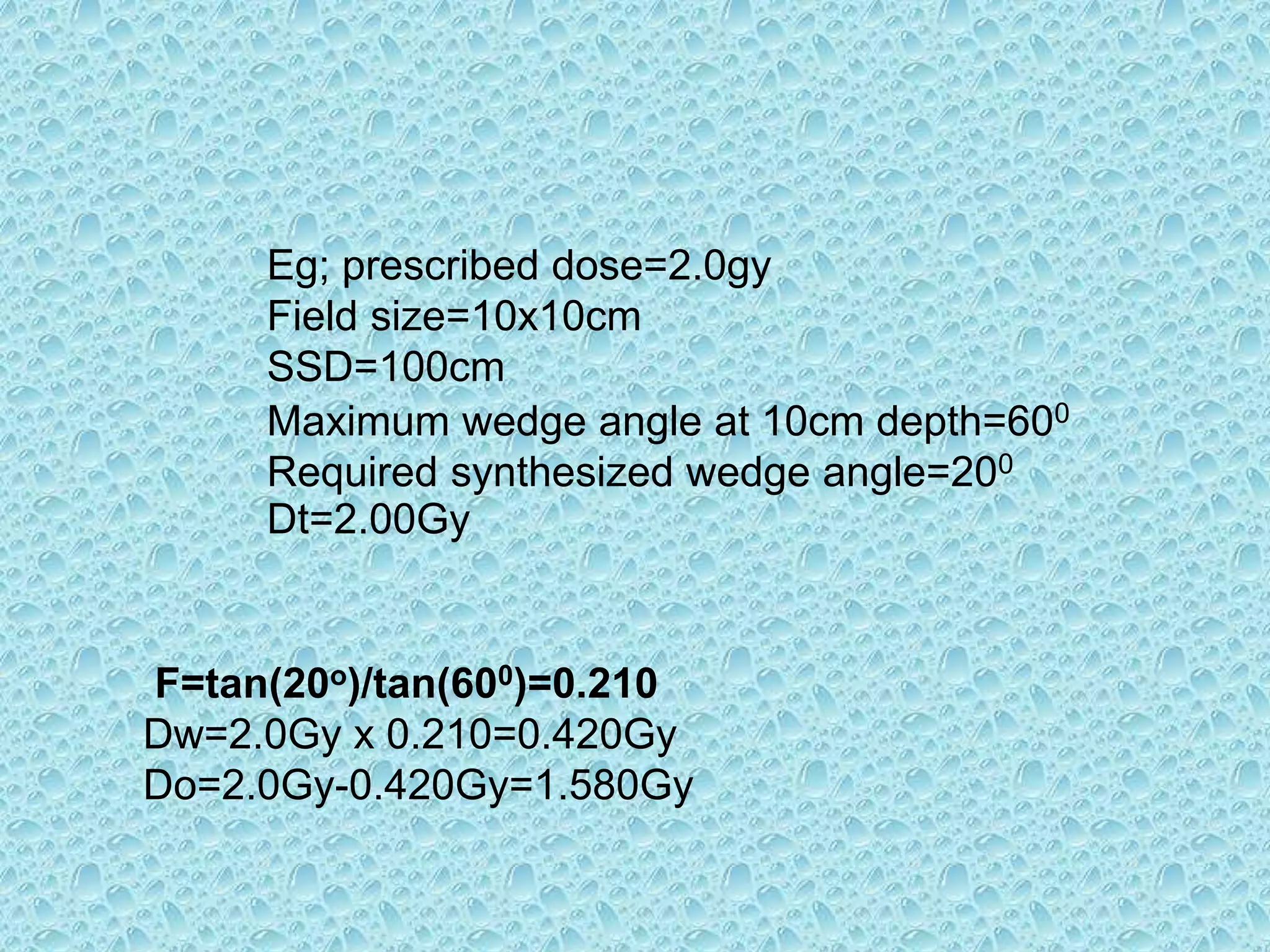
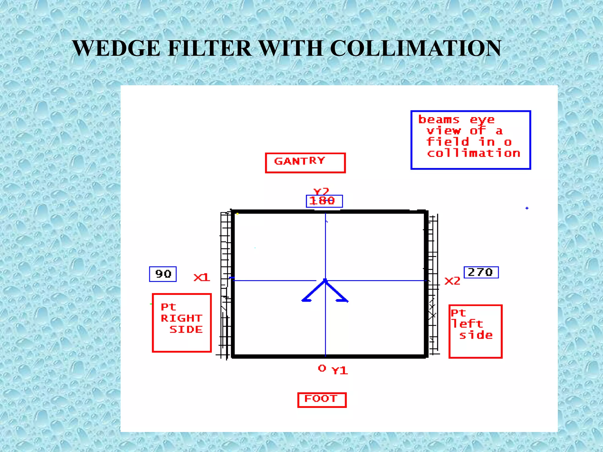
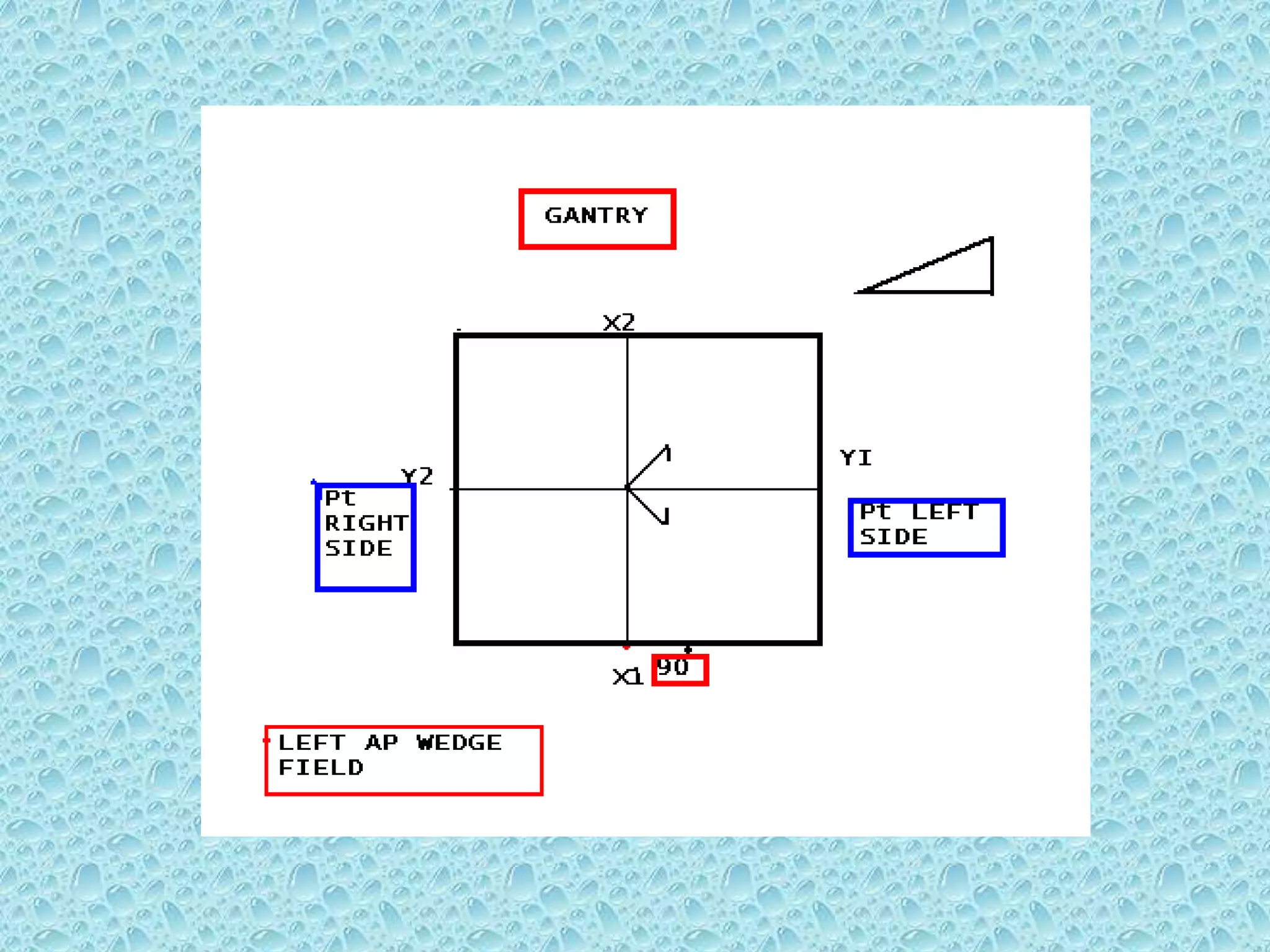
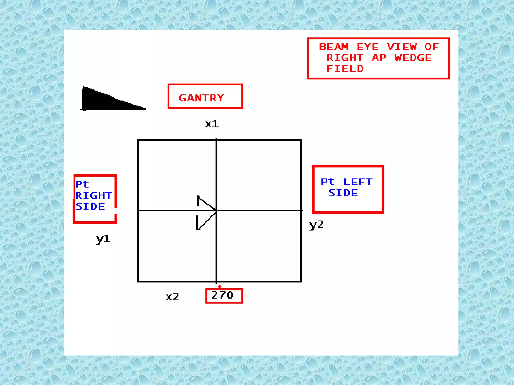
The wedge filter is located below the ionisation
chamber.
ѽ It is mounted on a motorised carriage fitted
permanently in the head of the gantry.
ѽThe facility has to provide a wide range of
synthetic wedge angels with the use of only
one wedge filter
4. The wedge filter has effective wedge angles of
60Oand can be used over field size from
1cm-1cm to 30cm-40cm.
A wedge field distribution for intermediate
angles is achieved by the combination of
the dose delivered for a wedge and an open
field of the same field size.
The use of wedged and open fields in different
ratios results in a range of intermediate
wedge angels between 00 to 600.
5. When a wedged field treatment is used the wedge is
moved in to and out of the radiation beam area under
software control.
Movement occurs while the radiation is not switched on.
The Software control makes sure the wedge filter is in one of its
two position in or out.
The required synthesized wedge angle can be derived by the
calculating the ratio of the open to fully wedged monitor
units
6. F=tan(x)/tan(y)
Dt=Do+Dw
Dw=Dt x F
Do=Dt-Dw
Do=Dw(1-F)/F)
F=Ratio of angle of synthesized wedged field to angle of
fully wedged field
Y=Maximum wedge angle defined for a specific field size
and depth.
x=synthesized wedge angle
Dt=Total dose on central axis at depth ‘d’
Dw=wedged segment dose on central axis at depth ‘d’
Do=open segment dose on central axis at depth ‘d’
7. Eg; prescribed dose=2.0gy
Field size=10x10cm
SSD=100cm
Maximum wedge angle at 10cm depth=600
Required synthesized wedge angle=200
Dt=2.00Gy
F=tan(20o)/tan(600)=0.210
Dw=2.0Gy x 0.210=0.420Gy
Do=2.0Gy-0.420Gy=1.580Gy