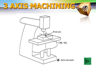
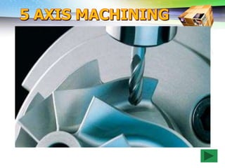
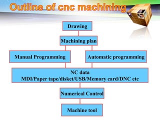
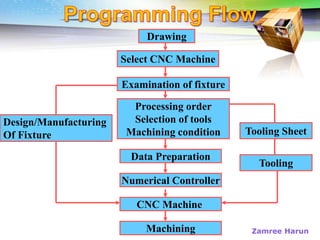
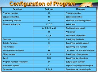
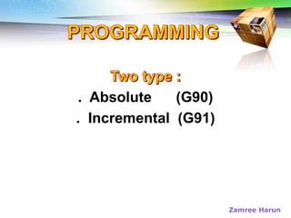
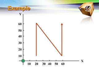
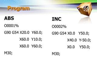
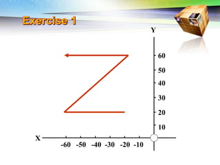
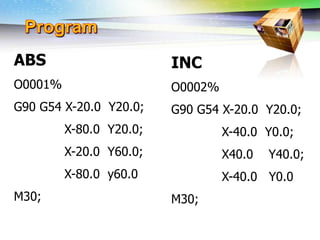
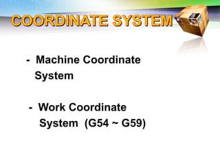
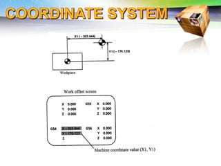
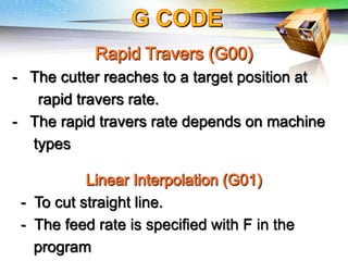
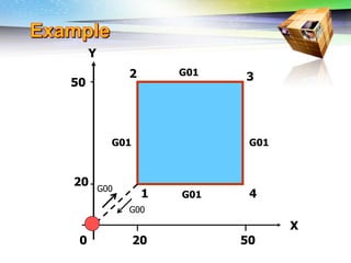
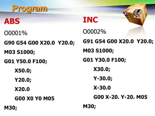
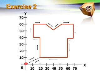
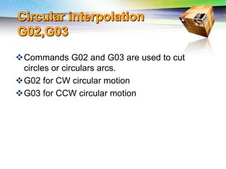
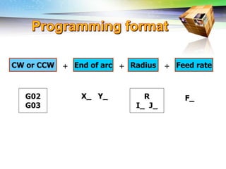
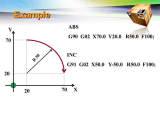
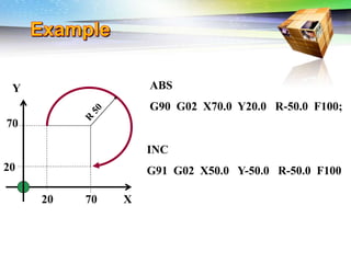
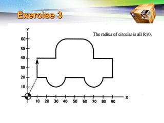
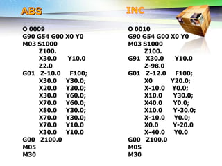
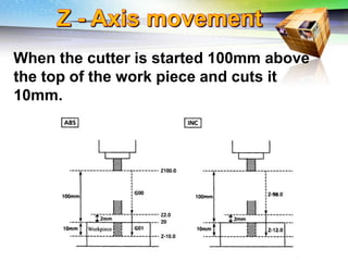
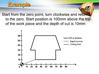
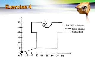
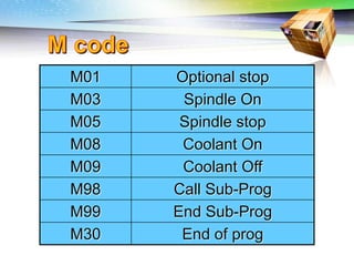
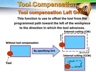
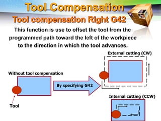
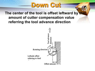
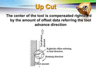
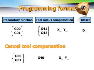
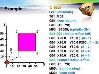
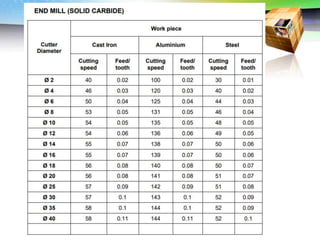
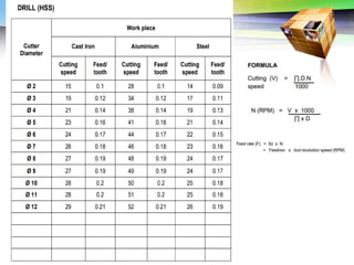
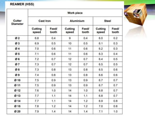
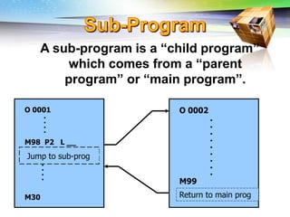
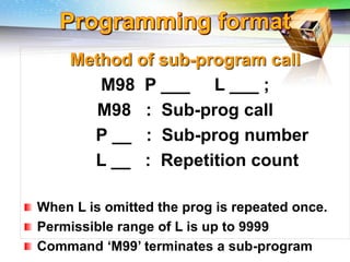
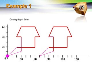
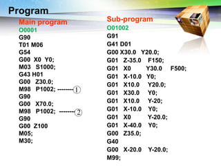
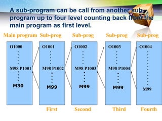
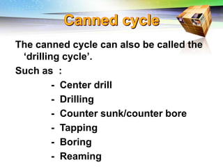
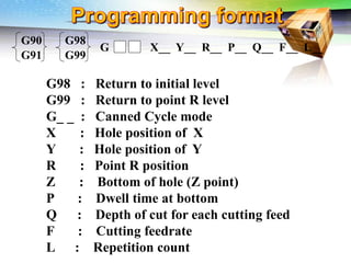
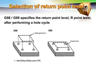
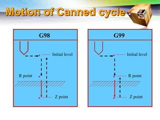
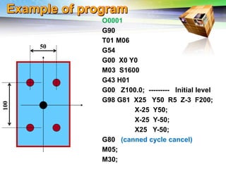
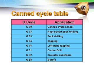
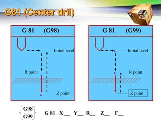
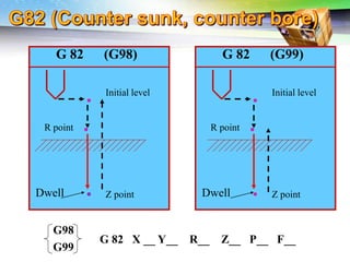
Presented by:
Zamree Bin Harun – ADTEC JERANTUT
Challenges of 5-Axis Machining
Drawing
Machining plan
Manual Programming Automatic programming
NC data
MDI/Paper tape/disket/USB/Memory card/DNC etc
Numerical Control
Machine tool
Challenges of 5-Axis Machining
Drawing
Select CNC Machine
Examination of fixture
Processing order
Selection of tools
Machining condition
Data Preparation
Numerical Controller
Tooling Sheet
Tooling
Design/Manufacturing
Of Fixture
Machining
CNC Machine
Zamree Harun
Challenges of 5-Axis Machining
Function Address Meaning
Program number O Program number
Sequence number N Sequence number
Preparatory function G Selection of traveling mode
Dimensional words X, Y, Z Axis travel
A, B, C, U, V, W Additional axis travel
R Arc radius
I, J, K Arc center coordinate
Feed rate F Specifying feed rate
Spindle function S Specifying spindle speed
Tool function T Specifying tool number
Miscellaneous function M On/Off ctrl for machine function
Offset number H, D Specifying offset number
Dwell P, X Specifying dwelling time
Program number command P Subprogram number
Number of repeats L repeat sub prog/canned cycle
Parameter P, Q, R Parameter foe canned cycle
Challenges of 5-Axis Machining
. Absolute (G90)
. Incremental (G91)
Zamree Harun
Challenges of 5-Axis Machining
40
50
60
10 20 30 40 50 60
10
20
30
Y
X
Challenges of 5-Axis Machining
ABS
O0001%
G90 G54 X20.0 Y60.0;
X60.0 Y10.0;
X60.0 Y60.0;
M30;
INC
O0002%
G90 G54 X0.0 Y50.0;
X40.0 Y-50.0;
X0.0 Y50.0;
M30;
Challenges of 5-Axis Machining
-60 -50 -40 -30 -20 -10
10
20
30
40
50
60
Y
X
Challenges of 5-Axis Machining
ABS
O0001%
G90 G54 X-20.0 Y20.0;
X-80.0 Y20.0;
X-20.0 Y60.0;
X-80.0 y60.0
M30;
INC
O0002%
G90 G54 X-20.0 Y20.0;
X-40.0 Y0.0;
X40.0 Y40.0;
X-40.0 Y0.0
M30;
Challenges of 5-Axis Machining
- Machine Coordinate
System
- Work Coordinate
System (G54 ~ G59)
Challenges of 5-Axis Machining
- The cutter reaches to a target position at
rapid travers rate.
- The rapid travers rate depends on machine
types
- To cut straight line.
- The feed rate is specified with F in the
program
Challenges of 5-Axis Machining
Y
20
50
20 50
X
1
2 3
4
G00
G00
G01
G01
G01
G01
0
Challenges of 5-Axis Machining
ABS
O0001%
G90 G54 G00 X20.0 Y20.0;
M03 S1000;
G01 Y50.0 F100;
X50.0;
Y20.0;
X20.0
G00 X0 Y0 M05
M30;
INC
O0002%
G91 G54 G00 X20.0 Y20.0;
M03 S1000;
G01 Y30.0 F100;
X30.0;
Y-30.0;
X-30.0
G00 X-20. Y-20. M05
M30;
Challenges of 5-Axis Machining
10 20 30 40 50 60 70
X
70
60
50
40
30
20
10
Y
0
Challenges of 5-Axis Machining
ABS
O0001%
G90 G54 G00 X20.0 Y20.0;
M03 S1000;
G01 Y50.0 F100;
X50.0;
Y20.0;
X20.0
G00 X0 Y0 M05
M30;
INC
O0002%
G91 G54 G00 X20.0 Y20.0;
M03 S1000;
G01 Y30.0 F100;
X30.0;
Y-30.0;
X-30.0
G00 X-20. Y-20. M05
M30;
Challenges of 5-Axis Machining
Commands G02 and G03 are used to cut
circles or circulars arcs.
G02 for CW circular motion
G03 for CCW circular motion
Challenges of 5-Axis Machining
CW or CCW End of arc Radius Feed rate
+ + +
G02
G03
R
I_ J_
F_
X_ Y_
Challenges of 5-Axis Machining
20 70
20
70
X
Y
ABS
G90 G02 X70.0 Y20.0 R50.0 F100;
INC
G91 G02 X50.0 Y-50.0 R50.0 F100;
Challenges of 5-Axis Machining
ABS
G90 G02 X70.0 Y20.0 R-50.0 F100;
INC
G91 G02 X50.0 Y-50.0 R-50.0 F100;
20 70
20
70
X
Y
Challenges of 5-Axis Machining
O 0009
G90 G54 G00 X0 Y0
M03 S1000
Z100.
X30.0 Y10.0
Z2.0
G01 Z-10.0 F100;
X30.0 Y30.0;
X20.0 Y30.0;
X30.0 Y60.0;
X70.0 Y60.0;
X80.0 Y30.0;
X70.0 Y30.0;
X70.0 Y10.0
X30.0 Y10.0
G00 Z100.0
M05
M30
O 0010
G90 G54 G00 X0 Y0
M03 S1000
Z100.
G91 X30.0 Y10.0
Z-98.0
G01 Z-12.0 F100;
X0 Y20.0;
X-10.0 Y0.0;
X10.0 Y30.0;
X40.0 Y0.0;
X10.0 Y-30.0;
X-10.0 Y0.0;
X0.0 Y-20.0
X-40.0 Y0.0
G00 Z100.0
M05
M30
Challenges of 5-Axis Machining
When the cutter is started 100mm above
the top of the work piece and cuts it
10mm.
Challenges of 5-Axis Machining
Start from the zero point, turn clockwise and return
to the zero. Start position is 100mm above the top
of the work piece and the depth of cut is 10mm
Challenges of 5-Axis Machining
O 0009
G90 G54 G00 X0 Y0
M03 S1000
Z100.
X30.0 Y10.0
Z2.0
G01 Z-10.0 F100;
X30.0 Y30.0;
X20.0 Y30.0;
X30.0 Y60.0;
X70.0 Y60.0;
X80.0 Y30.0;
X70.0 Y30.0;
X70.0 Y10.0
X30.0 Y10.0
G00 Z100.0
M05
M30
O 0010
G90 G54 G00 X0 Y0
M03 S1000
Z100.
G91 X30.0 Y10.0
Z-98.0
G01 Z-12.0 F100;
X0 Y20.0;
X-10.0 Y0.0;
X10.0 Y30.0;
X40.0 Y0.0;
X10.0 Y-30.0;
X-10.0 Y0.0;
X0.0 Y-20.0
X-40.0 Y0.0
G00 Z100.0
M05
M30
Challenges of 5-Axis Machining
M01 Optional stop
M03 Spindle On
M05 Spindle stop
M08 Coolant On
M09 Coolant Off
M98 Call Sub-Prog
M99 End Sub-Prog
M30 End of prog
Challenges of 5-Axis Machining
This function is use to offset the tool from the
programmed path toward the left of the workpiece
to the direction in which the tool advances.
By specifying G41
Tool
Without tool compensation
Internal cutting (CCW)
External cutting (CW)
Challenges of 5-Axis Machining
External cutting (CW)
By specifying G42
Tool
Without tool compensation
Internal cutting (CCW)
This function is use to offset the tool from the
programmed path toward the left of the workpiece
to the direction in which the tool advances.
Challenges of 5-Axis Machining
The center of the tool is offset leftward by the
amount of cutter compensation value
referring the tool advance direction
Challenges of 5-Axis Machining
The center of the tool is compensated rightward
by the amount of offset data referring the tool
advance direction
Challenges of 5-Axis Machining
Preparatory function Tool radius compensation Offset
D_
X_ Y_
G41
G42
G00
G01
G00
G01
G40 X_ Y_
Challenges of 5-Axis Machining
Example O 1002
G90 (absolute)
T01 M06
G54 (wcs/datum)
G00 X0 Y0;
M03 S1000; (spindle ON)
G41 D01 (radius offset left)
G00 X20.0 Y10.0 ; (0 - 1)
G01 X20.0 Y50.0 F200; (1 – 2)
G01 X50.0 Y50.0; (2 – 3)
G01 X50.0 Y20.0; (3 – 4)
G01 X10.0 Y20.0; (4 – 1)
G40 (cancel radius offset)
G00 X0 Y0;
M05; (spindle stop)
M30; (prog end)
10 20 30 40 50
10
20
30
40
50
X
Y
1
2 3
4
5
Challenges of 5-Axis Machining
O1002%
G90
T01 M06
G54
G00 X-20 Y-20 (Start point)
M03 S2000
G43 H01
G00 Z30
G01 Z-5 F150
M08
G41 D01
G01 X5 Y-20 F600 (sp – 0)
G01 X5 Y5 (0 – 1)
G01 X5 Y75 (1 – 2)
G01 X25 Y95 (2 – 3)
G01 X75 Y95 (3 - 4)
G02 X95 Y75 R20 (4 – 5)
G01 X95 Y25 (5 – 6)
G03 X75 Y5 R20 (6 – 7)
G01 X5 Y5 (7 – 8)
G01 X-20 Y5
G40
G01 X0 Y0
G00 Z100
M09
M05
M30
Challenges of 5-Axis Machining
O1002%
G90
T01 M06
G54
G00 X-20 Y-20 (Start point)
M03 S2000
G43 H01
G00 Z30
G01 Z-5 F150
M08
G41 D01
G01 X5 Y-20 F600 (Sp – 0)
G01 X5 Y5 (0 – 1)
G91
G01 X0 Y70 (1 – 2)
G01 X20 Y20 (2 – 3)
G01 X50 Y0 (3 - 4)
G02 X20 Y-20 R20 (4 – 5)
G01 X0 Y-50 (5 – 6)
G03 X-20 Y-20 R20 (6 – 7)
G01 X-70 Y0 (7 – 8)
G01 X-25 Y0
G90
G40
G01 X-20 Y-20
G00 Z100
M09
M05
M30
Challenges of 5-Axis Machining
O1002% (Island)
G90
T01 M06
G54
G00 X-20 Y50 (Start point)
M03 S2000
G43 H01
G00 Z30
G01 Z-5 F150
M08
G41 D01
G01 X-20 Y25 F600 (Sp – 0)
G03 X5 Y50 R25 (0 – 1)
G91
G01 X0 Y40 (1 – 2)
G02 X5 Y5 R5 (2 – 3)
G01 X80 Y0 (3 - 4)
G02 X5 Y-5 R5 (4 – 5)
G01 X0 Y-80 (5 – 6)
G02 X-5 Y-5 R5 (6 – 7)
G01 X-80 Y0 (7 – 8)
G02 X-5 Y5 R5 (8 – 9)
G01 X0 Y40 (9 – 10)
G03 X-25 Y25 R25 (10 – 11)
G90
G40
G01 X-20 Y50
G00 Z100
M09
M05
M30
O1003% (Pocket)
G90
T01 M06
G54
G00 X50 Y50 (Start point)
M03 S2000
G43 H01
G00 Z30
G01 Z-5 F150
M08
G41 D01
G01 X-20 Y25 F600 (Sp – 0)
G03 X5 Y50 R25 (0 – 1)
G91
G90
G40
G01 X-20 Y50
G00 Z100
M09
M05
M30
Challenges of 5-Axis Machining
G90 G91
Challenges of 5-Axis Machining
G90 (Absolute)
T01 M06 (END MILL DIA 16)
G54 (WCS/Datum)
G00 X-70 Y0 (Start point)
M03 S2000 (Spindle ON)
G43 H01 (Tool length offset)
G00 Z30 (30mm from top w/p)
G01 Z-5 F150 (5mm cutting depth)
M08 (Coolant ON)
G41 D01 (Tool radius offset – Left)
G01 X-70 Y-26 F500 (sp – 0)
G03 X-44 Y0 R26 (0 – 1)
G91 (Incremental)
G01 X0 Y34 (1 – 2)
G02 X10 Y10 R10 (2 – 3)
G01 X68 Y0 (3 – 4)
G02 X10 Y-10 R10 (4 – 5)
G01 X0 Y-68 (5 – 6)
G02 X-10 Y-10 R10 (6 – 7)
G01 X-68 Y0 (7 – 8)
G02 X-10 Y10 R10 (8 – 9)
G01 X0 Y34 (9 – 1)
G03 X-26 Y26 R26 (1 – 10)
G90 (Absolute)
G40 (Cancel -Tool radius offset)
G01 X-70 Y0 (10 – sp)
G00 Z100 (Angkat tool 100mm dari w/p)
T02 M06 (Tool change - Ball Nosedia 10)
G90 (Absolute)
G54 (wcs/datum)
M03 S2000 (Spindle ON- 2000 rpm)
G43 H02 (Tool length offset)
G00 X-32 Y30 (tempat tool nakturun no.11)
G01 Z-2 F150 (2mm cutting depth)
G01 X-32 Y-30 F500 (11 – 12)
G00 Z30 (angkat tool 30mm dari top w/p)
G00 X15 Y15 (12 – 13)
G01 Z-2 F150 (2mm cutting depth)
G03 X0 Y0 R-15 (13 – 14)
G02 X-15 Y-15 R-15 (14 – 15)
G00 Z30 (angkat tool 30mm dari top w/p)
G00 X32 Y30 (15 – 16)
G01 Z-2 F150 (2mm cutting depth)
G01 X32 Y-30 F500 (16 – 17)
G00 Z100 (Angkat tool 100mm dari w/p)
M09 (Coolant off)
M05 (Spindle stop)
M30 (Program end)
Challenges of 5-Axis Machining
Kelajuan pemotongan ialah panjang ukuran lilitan mata
pemotong dalam unit meter yang diukur apabila ia
berputar dalam masa satu minit (meter/minit). Contoh,
keluli lembut mempunyai kelajuan pemotongan 100
m/minit, ini bermakna spindal mesin perlu berputar
supaya ukuran lilitan mata pemotong itu 100 meter
dalam masa 1 minit.
Merupakan jumlah spindle mesin yang memegang
mata pemotong berpusing dalam tempoh masa 1
minit. Contohnya putaran spindle 1000 rpm
bermaksud spindle mesti melakukan putaran
sebanyak 1000 kali dalam tempoh masa 1 minit.
Challenges of 5-Axis Machining
A sub-program is a “child program”
which comes from a “parent
program” or “main program”.
O 0001
.
.
.
.
M98 P2 L __
.
.
.
.
M30
Jump to sub-prog
O 0002
.
.
.
.
.
.
.
.
.
M99
Return to main prog
Challenges of 5-Axis Machining
Method of sub-program call
M98 P ___ L ___ ;
M98 : Sub-prog call
P __ : Sub-prog number
L __ : Repetition count
When L is omitted the prog is repeated once.
Permissible range of L is up to 9999
Command ‘M99’ terminates a sub-program
Challenges of 5-Axis Machining
30 60 90 120 150
20
40
60
0
Cutting depth 5mm
Challenges of 5-Axis Machining
Program
Main program
O0001
G90
T01 M06
G54
G00 X0 Y0;
M03 S1000;
G43 H01
G00 Z30.0;
M98 P1002; --------
G90
G00 X70.0;
M98 P1002; --------
G90
G00 Z100
M05;
M30;
Sub-program
O01002
G91
G41 D01
G00 X30.0 Y20.0;
G01 Z-35.0 F150;
G01 X0 Y30.0 F500;
G01 X-10.0 Y0;
G01 X10.0 Y20.0;
G01 X30.0 Y0;
G01 X10.0 Y-20;
G01 X-10.0 Y0;
G01 X0 Y-20.0;
G01 X-40.0 Y0;
G00 Z35.0;
G40
G00 X-20.0 Y-20.0;
M99;
1
2
Challenges of 5-Axis Machining
Sub-prog
Fourth
Sub-prog
Third
Sub-prog
First
Sub-prog
Second
A sub-program can be call from another sub-
program up to four level counting back from the
main program as first level.
Main program
O1000
.
.
.
.
.
M98 P1001
O1001
.
.
.
.
.
M98 P1002
O1002
.
.
.
.
.
M98 P1003
O1003
.
.
.
.
.
M98 P1004
O1004
.
.
.
.
.
.
.
.
.
.
.
.
M99
.
.
.
.
M99
.
.
.
.
M30
.
.
.
.
M99
.
.
.
.
M99
Challenges of 5-Axis Machining
Start from the zero point, turn in clockwise direction and
return to the zero point.
Z axis start position : 100mm above the top of workpiece
Depth of cut : 5 mm
Challenges of 5-Axis Machining
Main Program
O0001%
G90
T01 M06
G54
G00 X0 Y0
M03 S1000;
G43 H01
G00 Z100.0;
M98 P1002;
G90 G00 X80.
M98 P1002;
G90 G00 X0 Y0
M05
M30
Sub- Program
O1002%
G91 G00 Z-95.0;
G41 X40.0 Y20.0 D01;
G01 Z-15.0 F100;
Y30.0;
X-10.0;
X10.0 Y30.0;
X40.0;
X10.0 Y-30.0;
X-10.0;
Y-20.0;
X-50.0;
G00 Z110.0;
G40 X-30.0 Y-30.0;
M99
Challenges of 5-Axis Machining
O1001%(MAIN PROGRAM)
G90 (Absolute programe)
T01 M06 (END MILL DIAMETER 16)
G54 (Datum workpiece)
G00 X-20 Y-20 (start point)
M03 S2000 (Spindle ON)
G43 H01 (Tool Length offset)
G00 Z30 (Tool move rapid 30mm from top wp)
G01 Z0 F150 (Tool move 0mm from top w/p)
M98 P1002 L20 (Call sub-prog 20 kali)
G00 Z100 (Angkat tool 100mm drwp)
M09 (Coolant OFF)
M05 (Spindle stop)
M30 (End of program)
O1002% (SUB-PROGRAM)
G91 (Incremental)
G01 Z-1 F150 (Depth of cut 1mm)
M08 (Coolant ON)
G90 (Absolute)
G41 D01 (Tool radius offset -Left)
G01 X10 Y-20 F500 (sp – 0)
G01 X10 Y10 (0 - 1)
G91 (Incremental)
G01 X0 Y80 (1 – 2)
G01 X80 Y0 (2 – 3)
G01 X0 Y-80 (3 – 4)
G01 X-80 Y0 (4 – 1)
G01 X-10 Y0 (1 – 5)
G90 (Absolute)
G40 (Tool radius offset cancel)
G01 X-20 Y-20 (5 – SP)
M99 (Sub-prog end)
Challenges of 5-Axis Machining
The canned cycle can also be called the
‘drilling cycle’.
Such as :
- Center drill
- Drilling
- Counter sunk/counter bore
- Tapping
- Boring
- Reaming
Challenges of 5-Axis Machining
G98 : Return to initial level
G99 : Return to point R level
G_ _ : Canned Cycle mode
X : Hole position of X
Y : Hole position of Y
R : Point R position
Z : Bottom of hole (Z point)
P : Dwell time at bottom
Q : Depth of cut for each cutting feed
F : Cutting feedrate
L : Repetition count
G X__ Y__ R__ P__ Q__ F__ L__
G90
G91
G98
G99
Challenges of 5-Axis Machining
G98 / G99 specifies the return point level, R point level,
after performing a hole cycle
Challenges of 5-Axis Machining
Initial level
Z point
R point
G98 G99
Initial level
Z point
R point
Challenges of 5-Axis Machining
O0001
G90
T01 M06
G54
G00 X0 Y0
M03 S1600
G43 H01
G00 Z100.0; --------- Initial level
G98 G81 X25 Y50 R5 Z-3 F200;
X-25 Y50;
X-25 Y-50;
X25 Y-50;
G80 (canned cycle cancel)
M05;
M30;
50
Challenges of 5-Axis Machining
G Code Application
G 80 Canned cycle cancel
G 73 High-speed peck drilling
G 83 Peck drilling
G 84 Tapping
G 74 Left-hand tapping
G 81 Center Drill
G 82 Counter sunk/bore
G 85 Boring
Challenges of 5-Axis Machining
G 81 (G99)
G 81 (G98)
Initial level
Z point
R point
Initial level
Z point
R point
G 81 X __ Y__ R__ Z__ F__
G98
G99
Challenges of 5-Axis Machining
G 82 (G99)
Initial level
Z point
R point
G 82 (G98)
Initial level
R point
Z point
G 82 X __ Y__ R__ Z__ P__ F__
G98
G99
Dwell Dwell
Challenges of 5-Axis Machining
G 73 (G99)
Initial level
Z point
G 73 (G98)
Initial level
Z point
R point
G 73 X __ Y__ R__ Z__ Q__ F__
G98
G99
Q
Q
Q
Q
R point
Challenges of 5-Axis Machining
G 83 (G99)
Initial level
Z point
R point
G 83 (G98)
Initial level
Z point
R point
G 83 X __ Y__ R__ Z__ Q__ F__
G98
G99
Q
Q
Q
Q
Challenges of 5-Axis Machining
Initial level
Z point
R point
G 84 (G99)
G 84 X __ Y__ R__ Z__ F__
G98
G99
Initial level
Z point
R point
G 84 (G98)
Spindle
CCW
Spindle
CW
Spindle
CCW
Spindle
CW
Challenges of 5-Axis Machining
G21
G00 G17 G40 G80 G49 G90
G91 G28 Z0
G90
T01 M06
G54
G00 X-55 Y-45
M03 S2000
G43 H01
G00 Z100
G00 Z30
G01 Z-1 F150
M08
G41 D01
G01 X-10 Y-45 F600
G01 X-10Y-17.5
G91
G01 X-10 Y0
G02 X-10 Y10 R10
G01 X0 Y15
G02 X10 Y10 R10
G01 X10 Y0
G01 X0 Y-5
G03 X20 Y0 R10
G01 X0 Y5
G01 X10 Y0
G02 X10 Y-10 R10
G01 X0 Y-15
G02 X-10 Y-10 R10
G01 X-10 Y0
G01 X0 Y5
G03 X-20 Y0 R10
G01 X0 Y-5
G01 X-15
G90
G00 X-55 Y-45
G00 Z100
M09
M05
G91 G28 Z0
T02 M06 (CENTER DRILL)
G90
G00 X-20 Y-7.5
M03 S1600
G43 H02
G00 Z100
G98 G81 X-20 Y-7.5 R5. Z-
3 F150
X-20 Y7.5
X20 Y7.5
X20 Y-7.5
G80
G00 Z100
M09
G91 G28 Z0
T03 M06 (DRILL DIA 6.8)
G90
G00 X-20 Y-7.5
M03 S2000
G43 H03
G00 Z100
G98 G83 X-20 Y-7.5 R5. Z-20 Q1
F350
X-20 Y7.5
X20 Y7.5
X20 Y-7.5
G80
G00 Z100
M09
G91 G28 Z0
M05
M30
Challenges of 5-Axis Machining

CNC MILLING.ppt

  • 1.
    Presented by: Zamree BinHarun – ADTEC JERANTUT
  • 2.
  • 3.
  • 4.
  • 5.
  • 6.
  • 7.
    Challenges of 5-AxisMachining Drawing Machining plan Manual Programming Automatic programming NC data MDI/Paper tape/disket/USB/Memory card/DNC etc Numerical Control Machine tool
  • 8.
    Challenges of 5-AxisMachining Drawing Select CNC Machine Examination of fixture Processing order Selection of tools Machining condition Data Preparation Numerical Controller Tooling Sheet Tooling Design/Manufacturing Of Fixture Machining CNC Machine Zamree Harun
  • 9.
    Challenges of 5-AxisMachining Function Address Meaning Program number O Program number Sequence number N Sequence number Preparatory function G Selection of traveling mode Dimensional words X, Y, Z Axis travel A, B, C, U, V, W Additional axis travel R Arc radius I, J, K Arc center coordinate Feed rate F Specifying feed rate Spindle function S Specifying spindle speed Tool function T Specifying tool number Miscellaneous function M On/Off ctrl for machine function Offset number H, D Specifying offset number Dwell P, X Specifying dwelling time Program number command P Subprogram number Number of repeats L repeat sub prog/canned cycle Parameter P, Q, R Parameter foe canned cycle
  • 10.
    Challenges of 5-AxisMachining . Absolute (G90) . Incremental (G91) Zamree Harun
  • 11.
    Challenges of 5-AxisMachining 40 50 60 10 20 30 40 50 60 10 20 30 Y X
  • 12.
    Challenges of 5-AxisMachining ABS O0001% G90 G54 X20.0 Y60.0; X60.0 Y10.0; X60.0 Y60.0; M30; INC O0002% G90 G54 X0.0 Y50.0; X40.0 Y-50.0; X0.0 Y50.0; M30;
  • 13.
    Challenges of 5-AxisMachining -60 -50 -40 -30 -20 -10 10 20 30 40 50 60 Y X
  • 14.
    Challenges of 5-AxisMachining ABS O0001% G90 G54 X-20.0 Y20.0; X-80.0 Y20.0; X-20.0 Y60.0; X-80.0 y60.0 M30; INC O0002% G90 G54 X-20.0 Y20.0; X-40.0 Y0.0; X40.0 Y40.0; X-40.0 Y0.0 M30;
  • 15.
    Challenges of 5-AxisMachining - Machine Coordinate System - Work Coordinate System (G54 ~ G59)
  • 16.
  • 17.
    Challenges of 5-AxisMachining - The cutter reaches to a target position at rapid travers rate. - The rapid travers rate depends on machine types - To cut straight line. - The feed rate is specified with F in the program
  • 18.
    Challenges of 5-AxisMachining Y 20 50 20 50 X 1 2 3 4 G00 G00 G01 G01 G01 G01 0
  • 19.
    Challenges of 5-AxisMachining ABS O0001% G90 G54 G00 X20.0 Y20.0; M03 S1000; G01 Y50.0 F100; X50.0; Y20.0; X20.0 G00 X0 Y0 M05 M30; INC O0002% G91 G54 G00 X20.0 Y20.0; M03 S1000; G01 Y30.0 F100; X30.0; Y-30.0; X-30.0 G00 X-20. Y-20. M05 M30;
  • 20.
    Challenges of 5-AxisMachining 10 20 30 40 50 60 70 X 70 60 50 40 30 20 10 Y 0
  • 21.
    Challenges of 5-AxisMachining ABS O0001% G90 G54 G00 X20.0 Y20.0; M03 S1000; G01 Y50.0 F100; X50.0; Y20.0; X20.0 G00 X0 Y0 M05 M30; INC O0002% G91 G54 G00 X20.0 Y20.0; M03 S1000; G01 Y30.0 F100; X30.0; Y-30.0; X-30.0 G00 X-20. Y-20. M05 M30;
  • 22.
    Challenges of 5-AxisMachining Commands G02 and G03 are used to cut circles or circulars arcs. G02 for CW circular motion G03 for CCW circular motion
  • 23.
    Challenges of 5-AxisMachining CW or CCW End of arc Radius Feed rate + + + G02 G03 R I_ J_ F_ X_ Y_
  • 24.
    Challenges of 5-AxisMachining 20 70 20 70 X Y ABS G90 G02 X70.0 Y20.0 R50.0 F100; INC G91 G02 X50.0 Y-50.0 R50.0 F100;
  • 25.
    Challenges of 5-AxisMachining ABS G90 G02 X70.0 Y20.0 R-50.0 F100; INC G91 G02 X50.0 Y-50.0 R-50.0 F100; 20 70 20 70 X Y
  • 26.
  • 27.
    Challenges of 5-AxisMachining O 0009 G90 G54 G00 X0 Y0 M03 S1000 Z100. X30.0 Y10.0 Z2.0 G01 Z-10.0 F100; X30.0 Y30.0; X20.0 Y30.0; X30.0 Y60.0; X70.0 Y60.0; X80.0 Y30.0; X70.0 Y30.0; X70.0 Y10.0 X30.0 Y10.0 G00 Z100.0 M05 M30 O 0010 G90 G54 G00 X0 Y0 M03 S1000 Z100. G91 X30.0 Y10.0 Z-98.0 G01 Z-12.0 F100; X0 Y20.0; X-10.0 Y0.0; X10.0 Y30.0; X40.0 Y0.0; X10.0 Y-30.0; X-10.0 Y0.0; X0.0 Y-20.0 X-40.0 Y0.0 G00 Z100.0 M05 M30
  • 28.
    Challenges of 5-AxisMachining When the cutter is started 100mm above the top of the work piece and cuts it 10mm.
  • 29.
    Challenges of 5-AxisMachining Start from the zero point, turn clockwise and return to the zero. Start position is 100mm above the top of the work piece and the depth of cut is 10mm
  • 30.
    Challenges of 5-AxisMachining O 0009 G90 G54 G00 X0 Y0 M03 S1000 Z100. X30.0 Y10.0 Z2.0 G01 Z-10.0 F100; X30.0 Y30.0; X20.0 Y30.0; X30.0 Y60.0; X70.0 Y60.0; X80.0 Y30.0; X70.0 Y30.0; X70.0 Y10.0 X30.0 Y10.0 G00 Z100.0 M05 M30 O 0010 G90 G54 G00 X0 Y0 M03 S1000 Z100. G91 X30.0 Y10.0 Z-98.0 G01 Z-12.0 F100; X0 Y20.0; X-10.0 Y0.0; X10.0 Y30.0; X40.0 Y0.0; X10.0 Y-30.0; X-10.0 Y0.0; X0.0 Y-20.0 X-40.0 Y0.0 G00 Z100.0 M05 M30
  • 31.
  • 32.
    Challenges of 5-AxisMachining O 0009 G90 G54 G00 X0 Y0 M03 S1000 Z100. X30.0 Y10.0 Z2.0 G01 Z-10.0 F100; X30.0 Y30.0; X20.0 Y30.0; X30.0 Y60.0; X70.0 Y60.0; X80.0 Y30.0; X70.0 Y30.0; X70.0 Y10.0 X30.0 Y10.0 G00 Z100.0 M05 M30 O 0010 G90 G54 G00 X0 Y0 M03 S1000 Z100. G91 X30.0 Y10.0 Z-98.0 G01 Z-12.0 F100; X0 Y20.0; X-10.0 Y0.0; X10.0 Y30.0; X40.0 Y0.0; X10.0 Y-30.0; X-10.0 Y0.0; X0.0 Y-20.0 X-40.0 Y0.0 G00 Z100.0 M05 M30
  • 33.
    Challenges of 5-AxisMachining M01 Optional stop M03 Spindle On M05 Spindle stop M08 Coolant On M09 Coolant Off M98 Call Sub-Prog M99 End Sub-Prog M30 End of prog
  • 34.
    Challenges of 5-AxisMachining This function is use to offset the tool from the programmed path toward the left of the workpiece to the direction in which the tool advances. By specifying G41 Tool Without tool compensation Internal cutting (CCW) External cutting (CW)
  • 35.
    Challenges of 5-AxisMachining External cutting (CW) By specifying G42 Tool Without tool compensation Internal cutting (CCW) This function is use to offset the tool from the programmed path toward the left of the workpiece to the direction in which the tool advances.
  • 36.
    Challenges of 5-AxisMachining The center of the tool is offset leftward by the amount of cutter compensation value referring the tool advance direction
  • 37.
    Challenges of 5-AxisMachining The center of the tool is compensated rightward by the amount of offset data referring the tool advance direction
  • 38.
    Challenges of 5-AxisMachining Preparatory function Tool radius compensation Offset D_ X_ Y_ G41 G42 G00 G01 G00 G01 G40 X_ Y_
  • 39.
    Challenges of 5-AxisMachining Example O 1002 G90 (absolute) T01 M06 G54 (wcs/datum) G00 X0 Y0; M03 S1000; (spindle ON) G41 D01 (radius offset left) G00 X20.0 Y10.0 ; (0 - 1) G01 X20.0 Y50.0 F200; (1 – 2) G01 X50.0 Y50.0; (2 – 3) G01 X50.0 Y20.0; (3 – 4) G01 X10.0 Y20.0; (4 – 1) G40 (cancel radius offset) G00 X0 Y0; M05; (spindle stop) M30; (prog end) 10 20 30 40 50 10 20 30 40 50 X Y 1 2 3 4 5
  • 40.
  • 41.
    Challenges of 5-AxisMachining O1002% G90 T01 M06 G54 G00 X-20 Y-20 (Start point) M03 S2000 G43 H01 G00 Z30 G01 Z-5 F150 M08 G41 D01 G01 X5 Y-20 F600 (sp – 0) G01 X5 Y5 (0 – 1) G01 X5 Y75 (1 – 2) G01 X25 Y95 (2 – 3) G01 X75 Y95 (3 - 4) G02 X95 Y75 R20 (4 – 5) G01 X95 Y25 (5 – 6) G03 X75 Y5 R20 (6 – 7) G01 X5 Y5 (7 – 8) G01 X-20 Y5 G40 G01 X0 Y0 G00 Z100 M09 M05 M30
  • 42.
  • 43.
    Challenges of 5-AxisMachining O1002% G90 T01 M06 G54 G00 X-20 Y-20 (Start point) M03 S2000 G43 H01 G00 Z30 G01 Z-5 F150 M08 G41 D01 G01 X5 Y-20 F600 (Sp – 0) G01 X5 Y5 (0 – 1) G91 G01 X0 Y70 (1 – 2) G01 X20 Y20 (2 – 3) G01 X50 Y0 (3 - 4) G02 X20 Y-20 R20 (4 – 5) G01 X0 Y-50 (5 – 6) G03 X-20 Y-20 R20 (6 – 7) G01 X-70 Y0 (7 – 8) G01 X-25 Y0 G90 G40 G01 X-20 Y-20 G00 Z100 M09 M05 M30
  • 44.
  • 45.
    Challenges of 5-AxisMachining O1002% (Island) G90 T01 M06 G54 G00 X-20 Y50 (Start point) M03 S2000 G43 H01 G00 Z30 G01 Z-5 F150 M08 G41 D01 G01 X-20 Y25 F600 (Sp – 0) G03 X5 Y50 R25 (0 – 1) G91 G01 X0 Y40 (1 – 2) G02 X5 Y5 R5 (2 – 3) G01 X80 Y0 (3 - 4) G02 X5 Y-5 R5 (4 – 5) G01 X0 Y-80 (5 – 6) G02 X-5 Y-5 R5 (6 – 7) G01 X-80 Y0 (7 – 8) G02 X-5 Y5 R5 (8 – 9) G01 X0 Y40 (9 – 10) G03 X-25 Y25 R25 (10 – 11) G90 G40 G01 X-20 Y50 G00 Z100 M09 M05 M30 O1003% (Pocket) G90 T01 M06 G54 G00 X50 Y50 (Start point) M03 S2000 G43 H01 G00 Z30 G01 Z-5 F150 M08 G41 D01 G01 X-20 Y25 F600 (Sp – 0) G03 X5 Y50 R25 (0 – 1) G91 G90 G40 G01 X-20 Y50 G00 Z100 M09 M05 M30
  • 46.
    Challenges of 5-AxisMachining G90 G91
  • 47.
  • 48.
    Challenges of 5-AxisMachining G90 (Absolute) T01 M06 (END MILL DIA 16) G54 (WCS/Datum) G00 X-70 Y0 (Start point) M03 S2000 (Spindle ON) G43 H01 (Tool length offset) G00 Z30 (30mm from top w/p) G01 Z-5 F150 (5mm cutting depth) M08 (Coolant ON) G41 D01 (Tool radius offset – Left) G01 X-70 Y-26 F500 (sp – 0) G03 X-44 Y0 R26 (0 – 1) G91 (Incremental) G01 X0 Y34 (1 – 2) G02 X10 Y10 R10 (2 – 3) G01 X68 Y0 (3 – 4) G02 X10 Y-10 R10 (4 – 5) G01 X0 Y-68 (5 – 6) G02 X-10 Y-10 R10 (6 – 7) G01 X-68 Y0 (7 – 8) G02 X-10 Y10 R10 (8 – 9) G01 X0 Y34 (9 – 1) G03 X-26 Y26 R26 (1 – 10) G90 (Absolute) G40 (Cancel -Tool radius offset) G01 X-70 Y0 (10 – sp) G00 Z100 (Angkat tool 100mm dari w/p) T02 M06 (Tool change - Ball Nosedia 10) G90 (Absolute) G54 (wcs/datum) M03 S2000 (Spindle ON- 2000 rpm) G43 H02 (Tool length offset) G00 X-32 Y30 (tempat tool nakturun no.11) G01 Z-2 F150 (2mm cutting depth) G01 X-32 Y-30 F500 (11 – 12) G00 Z30 (angkat tool 30mm dari top w/p) G00 X15 Y15 (12 – 13) G01 Z-2 F150 (2mm cutting depth) G03 X0 Y0 R-15 (13 – 14) G02 X-15 Y-15 R-15 (14 – 15) G00 Z30 (angkat tool 30mm dari top w/p) G00 X32 Y30 (15 – 16) G01 Z-2 F150 (2mm cutting depth) G01 X32 Y-30 F500 (16 – 17) G00 Z100 (Angkat tool 100mm dari w/p) M09 (Coolant off) M05 (Spindle stop) M30 (Program end)
  • 49.
    Challenges of 5-AxisMachining Kelajuan pemotongan ialah panjang ukuran lilitan mata pemotong dalam unit meter yang diukur apabila ia berputar dalam masa satu minit (meter/minit). Contoh, keluli lembut mempunyai kelajuan pemotongan 100 m/minit, ini bermakna spindal mesin perlu berputar supaya ukuran lilitan mata pemotong itu 100 meter dalam masa 1 minit. Merupakan jumlah spindle mesin yang memegang mata pemotong berpusing dalam tempoh masa 1 minit. Contohnya putaran spindle 1000 rpm bermaksud spindle mesti melakukan putaran sebanyak 1000 kali dalam tempoh masa 1 minit.
  • 50.
  • 51.
  • 52.
  • 53.
  • 54.
  • 55.
    Challenges of 5-AxisMachining A sub-program is a “child program” which comes from a “parent program” or “main program”. O 0001 . . . . M98 P2 L __ . . . . M30 Jump to sub-prog O 0002 . . . . . . . . . M99 Return to main prog
  • 56.
    Challenges of 5-AxisMachining Method of sub-program call M98 P ___ L ___ ; M98 : Sub-prog call P __ : Sub-prog number L __ : Repetition count When L is omitted the prog is repeated once. Permissible range of L is up to 9999 Command ‘M99’ terminates a sub-program
  • 57.
    Challenges of 5-AxisMachining 30 60 90 120 150 20 40 60 0 Cutting depth 5mm
  • 58.
    Challenges of 5-AxisMachining Program Main program O0001 G90 T01 M06 G54 G00 X0 Y0; M03 S1000; G43 H01 G00 Z30.0; M98 P1002; -------- G90 G00 X70.0; M98 P1002; -------- G90 G00 Z100 M05; M30; Sub-program O01002 G91 G41 D01 G00 X30.0 Y20.0; G01 Z-35.0 F150; G01 X0 Y30.0 F500; G01 X-10.0 Y0; G01 X10.0 Y20.0; G01 X30.0 Y0; G01 X10.0 Y-20; G01 X-10.0 Y0; G01 X0 Y-20.0; G01 X-40.0 Y0; G00 Z35.0; G40 G00 X-20.0 Y-20.0; M99; 1 2
  • 59.
    Challenges of 5-AxisMachining Sub-prog Fourth Sub-prog Third Sub-prog First Sub-prog Second A sub-program can be call from another sub- program up to four level counting back from the main program as first level. Main program O1000 . . . . . M98 P1001 O1001 . . . . . M98 P1002 O1002 . . . . . M98 P1003 O1003 . . . . . M98 P1004 O1004 . . . . . . . . . . . . M99 . . . . M99 . . . . M30 . . . . M99 . . . . M99
  • 60.
    Challenges of 5-AxisMachining Start from the zero point, turn in clockwise direction and return to the zero point. Z axis start position : 100mm above the top of workpiece Depth of cut : 5 mm
  • 61.
    Challenges of 5-AxisMachining Main Program O0001% G90 T01 M06 G54 G00 X0 Y0 M03 S1000; G43 H01 G00 Z100.0; M98 P1002; G90 G00 X80. M98 P1002; G90 G00 X0 Y0 M05 M30 Sub- Program O1002% G91 G00 Z-95.0; G41 X40.0 Y20.0 D01; G01 Z-15.0 F100; Y30.0; X-10.0; X10.0 Y30.0; X40.0; X10.0 Y-30.0; X-10.0; Y-20.0; X-50.0; G00 Z110.0; G40 X-30.0 Y-30.0; M99
  • 62.
  • 63.
    Challenges of 5-AxisMachining O1001%(MAIN PROGRAM) G90 (Absolute programe) T01 M06 (END MILL DIAMETER 16) G54 (Datum workpiece) G00 X-20 Y-20 (start point) M03 S2000 (Spindle ON) G43 H01 (Tool Length offset) G00 Z30 (Tool move rapid 30mm from top wp) G01 Z0 F150 (Tool move 0mm from top w/p) M98 P1002 L20 (Call sub-prog 20 kali) G00 Z100 (Angkat tool 100mm drwp) M09 (Coolant OFF) M05 (Spindle stop) M30 (End of program) O1002% (SUB-PROGRAM) G91 (Incremental) G01 Z-1 F150 (Depth of cut 1mm) M08 (Coolant ON) G90 (Absolute) G41 D01 (Tool radius offset -Left) G01 X10 Y-20 F500 (sp – 0) G01 X10 Y10 (0 - 1) G91 (Incremental) G01 X0 Y80 (1 – 2) G01 X80 Y0 (2 – 3) G01 X0 Y-80 (3 – 4) G01 X-80 Y0 (4 – 1) G01 X-10 Y0 (1 – 5) G90 (Absolute) G40 (Tool radius offset cancel) G01 X-20 Y-20 (5 – SP) M99 (Sub-prog end)
  • 64.
    Challenges of 5-AxisMachining The canned cycle can also be called the ‘drilling cycle’. Such as : - Center drill - Drilling - Counter sunk/counter bore - Tapping - Boring - Reaming
  • 65.
    Challenges of 5-AxisMachining G98 : Return to initial level G99 : Return to point R level G_ _ : Canned Cycle mode X : Hole position of X Y : Hole position of Y R : Point R position Z : Bottom of hole (Z point) P : Dwell time at bottom Q : Depth of cut for each cutting feed F : Cutting feedrate L : Repetition count G X__ Y__ R__ P__ Q__ F__ L__ G90 G91 G98 G99
  • 66.
    Challenges of 5-AxisMachining G98 / G99 specifies the return point level, R point level, after performing a hole cycle
  • 67.
    Challenges of 5-AxisMachining Initial level Z point R point G98 G99 Initial level Z point R point
  • 68.
    Challenges of 5-AxisMachining O0001 G90 T01 M06 G54 G00 X0 Y0 M03 S1600 G43 H01 G00 Z100.0; --------- Initial level G98 G81 X25 Y50 R5 Z-3 F200; X-25 Y50; X-25 Y-50; X25 Y-50; G80 (canned cycle cancel) M05; M30; 50
  • 69.
    Challenges of 5-AxisMachining G Code Application G 80 Canned cycle cancel G 73 High-speed peck drilling G 83 Peck drilling G 84 Tapping G 74 Left-hand tapping G 81 Center Drill G 82 Counter sunk/bore G 85 Boring
  • 70.
    Challenges of 5-AxisMachining G 81 (G99) G 81 (G98) Initial level Z point R point Initial level Z point R point G 81 X __ Y__ R__ Z__ F__ G98 G99
  • 71.
    Challenges of 5-AxisMachining G 82 (G99) Initial level Z point R point G 82 (G98) Initial level R point Z point G 82 X __ Y__ R__ Z__ P__ F__ G98 G99 Dwell Dwell
  • 72.
    Challenges of 5-AxisMachining G 73 (G99) Initial level Z point G 73 (G98) Initial level Z point R point G 73 X __ Y__ R__ Z__ Q__ F__ G98 G99 Q Q Q Q R point
  • 73.
    Challenges of 5-AxisMachining G 83 (G99) Initial level Z point R point G 83 (G98) Initial level Z point R point G 83 X __ Y__ R__ Z__ Q__ F__ G98 G99 Q Q Q Q
  • 74.
    Challenges of 5-AxisMachining Initial level Z point R point G 84 (G99) G 84 X __ Y__ R__ Z__ F__ G98 G99 Initial level Z point R point G 84 (G98) Spindle CCW Spindle CW Spindle CCW Spindle CW
  • 75.
  • 76.
  • 77.
    Challenges of 5-AxisMachining G21 G00 G17 G40 G80 G49 G90 G91 G28 Z0 G90 T01 M06 G54 G00 X-55 Y-45 M03 S2000 G43 H01 G00 Z100 G00 Z30 G01 Z-1 F150 M08 G41 D01 G01 X-10 Y-45 F600 G01 X-10Y-17.5 G91 G01 X-10 Y0 G02 X-10 Y10 R10 G01 X0 Y15 G02 X10 Y10 R10 G01 X10 Y0 G01 X0 Y-5 G03 X20 Y0 R10 G01 X0 Y5 G01 X10 Y0 G02 X10 Y-10 R10 G01 X0 Y-15 G02 X-10 Y-10 R10 G01 X-10 Y0 G01 X0 Y5 G03 X-20 Y0 R10 G01 X0 Y-5 G01 X-15 G90 G00 X-55 Y-45 G00 Z100 M09 M05 G91 G28 Z0 T02 M06 (CENTER DRILL) G90 G00 X-20 Y-7.5 M03 S1600 G43 H02 G00 Z100 G98 G81 X-20 Y-7.5 R5. Z- 3 F150 X-20 Y7.5 X20 Y7.5 X20 Y-7.5 G80 G00 Z100 M09 G91 G28 Z0 T03 M06 (DRILL DIA 6.8) G90 G00 X-20 Y-7.5 M03 S2000 G43 H03 G00 Z100 G98 G83 X-20 Y-7.5 R5. Z-20 Q1 F350 X-20 Y7.5 X20 Y7.5 X20 Y-7.5 G80 G00 Z100 M09 G91 G28 Z0 M05 M30
  • 78.