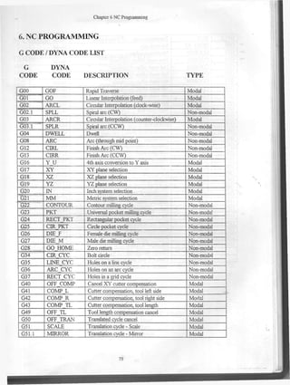
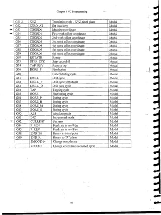
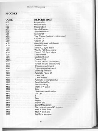
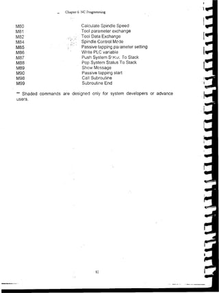
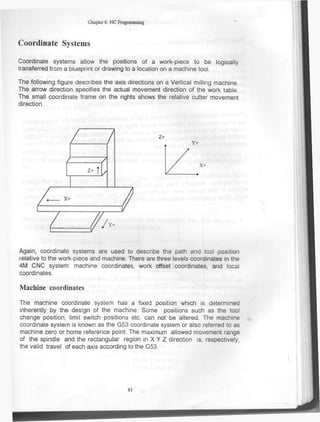
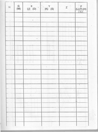
Chaptcr 6 NC Programniing
6. NC PROGRAMMJJNG
G CODE / DYNA CODE LIST
G DYNA
CODE CODE DESCR1PTION TYPE
G00 GOF Rapid Traverse Modal .
G01 GO Linear Interpolation (feed) Modal
G02 ARCL Circular Interpolation (clock-wise) Modal
G02.1 SPLL Spiral are (CW) Non-modal
G03 ARCR Circular Interpolation (counter-clockwise) Modal
G03.1 SPLR Spiral are (CCW) Non-modal
G04 DWELL Dwell Non-modal
G08 ARC Are (through mid point) Non-modal
G12 cniL Finish Are (CW) Non-modal
G13 CIRR Finish Are (CCW) Non-modal
G16 Y U 4th axis conversión to Y axis Modal
G17 X Y X Y plañe selection Modal
G18 XZ XZ plañe selection Modal
G19 YZ YZ plañe selection Modal
G20 m Inch system selection Modal
G21 M M Metric system selection Modal
G22 CONTOUR Contour milling eyele Non-modal
G23 PKT Universal pocket milling eyele Non-modal
G24 RECT PKT R-ectangular pocket eyele Non-modal
G25 CTR PKT Circle pocket eyele Non-modal
G26 DDE F Female die milling eyele Non-modal
G27 DDE M Male die milling eyele Non-modal
G28 GO HOME Zero retura Non-modal
G34 CIR CYC Bolt circle Non-modal
G35 U N E CYC Holes on a line eyele Non-modal
G36 ARC CYC Holes on an are eyele Non-modal
G37 RECT CYC Holes in a grid eyele Non-modal
G40 OFF COMP Cancel X Y cutter compensation Modal
G41 COMP L Cutter compensation, tool left side Modal
G42 COMP R Cutter compensation, tool right side Modal
G43 COMP TL Cutter compensation, tool length Modal
G49 OFF TL Tool length compensation cancel Modal
G50 OFF TRAN Translated eyele cancel Modal
G51 SCALE Translation eyele - Scale Modal
G51.1 MIRROR Translation eyele - Mrror Modal
79
Chapter 6 NC Prograrruning
G51.2 XYZ Translation cycle - XYZ tilted plañe Modal
G52 ZERO AT Set local zero Modal
G53 COORDO Machine coordínate Modal
G54 COORD1 First work offset coordínate Modal
G55 COORD2 2nd work offset coordínate Modal
G56 COORD3 3rd work offset coordínate Modal
G57 COORD4 4th work offset coordínate Modal
G58 COORD5 5th work offset coordínate Modal
G59 COORD6 6th work offset coordínate Modal
G68 ROTATE Rotate Modal
G73 STEP CYC Step cycle drill Modal
G74 TAP REV Reverse tap Modal
G76 BORE F Fine boring Modal
G80 Cancel drilling cycle Modal
G81 DRILL Drill cycle Modal
G82 DRILL P Drill cycle with dwell Modal
G83 DRILL Q Drill peck cycle Modal
G84 TAP Tapping cycle Modal
G85 BORE Fine boring cycle Modal
G86 BORE P Boring cycle Modal
G87 BORE B Boring cycle Modal
G88 BORE M Boring cycle Modal
G89 BORE S Boring cycle Modal
G90 ABS Absolute mode Modal
G91 INC Incremental mode Modal
G92 CURRENT Set zero Modal
G94 F MTN ¡ Feed rate in mm/Min. Modal
G95 F REV l
1 Feed rate in mm/F ev.
Modal
G98 END ZO Rerum to initial point Modal
G99 END R Return to "R" plañe Modal
SMOOTH= Change smooth rate Modal
ZFEED= Change Z feed rate in canned cycle Modal
80
Chapter 6: NC Programming
M CODES
C O D E D E S C R I P T I O N
M00 Program Stop
M01 Optional Stop
M02 Program End
M03 Spindle Forward
M04 Spindle Reverse
M05 Spindle Off
M06 Tool Change (optional - not require
M08 Coolant On
M09 Coolant Off
MÍ 0 Automatic spare tool change
M19 Spindle Orient
M22 Send PLC Sync. signal
M23 Wait for PLC Sync. signal
M24 Turn off PLC Sync. signal
M25 Load counter
M26 Start count down
M30 Program End
M31 Turn on the 2nd coolant pump
M32 Turn off the 2nd coolant pump
M35 Chip conveyor forward
M36 Chip conveyor backward
M37 Stop Chip conveyor
M39 Automatic Power Off
M40 U axis lock
M41 U axis reléase
M42 Automatic tool length setup
M60 Reset Status Flag
M61 Set Status Flag
M62 Wait For A Signal
M64 Skip
M65 Direct command to driver
M70 Cali DNC
M71 If
M72 Goto
M73 Repeat
M74 Repeat End
M75 End of NC program
M76 Start executing new NC program
M77 Mark A Block Start
M78 Mark A Block End
M79 Cali Error Message
si
Chapter 6: NC Programming
M80 Calcúlate Spindle Speed
M81 Tool parameter exchange
M82 Tool Data Exchange
M84 Spindle Control Mode
M85 Passive tapping parameter setting
M86 Write PLC variable
M87 Push System Stalus To Stack
M88 Pop System Status To Stack
M89 Show Message
M90 Passive tapping start
M98 Cali Subroutine
M99 Subroutine End
** Shaded commands are designed only for system developers or advance
users.
82
Chapter 6: NC Programming
Coordínate Systems
Coordínate systems allow the posítions of a work-píece to be logícally
transferred frem a biueprint or drawing to a location on a machine tool.
The following figure describes the axis directions on a Vertical milling machine.
The arrow direction specifies the actual movement direction of the work table.
The small coordínate frame on the rights shows the relative cutter movement
direction.
Again, coordínate systems are used to describe the path and tocí position
relative to the work-piece and machine. There are three levéis coordinates in the
4M CNC system: machine coordinates, work offset coordinates, and locai
coordinates.
Machine coordinates
The machine coordínate system has a fixed position which ¡s determined
inherently by the design of the machine. Some positions such as the tool
change position, limit swítch posítions etc. can not be altered. The machine
coordínate system is known as the G53 coordínate system or also referred to as
machine zero or home reference point. The máximum allowed movement range
of the spindle and the rectangular región in X Y Z direction is, respectively,
the valid travel of each axis according to the G53.
83
N G
(M)
X
(J) (D) '
Y
(K) (S)
Z F
(L) (T) (H)
4
•
— -— -
-
— - - —— - - —
- j
——
-
———

Codigos de-programacion cnc

  • 1.
    Chaptcr 6 NCProgramniing 6. NC PROGRAMMJJNG G CODE / DYNA CODE LIST G DYNA CODE CODE DESCR1PTION TYPE G00 GOF Rapid Traverse Modal . G01 GO Linear Interpolation (feed) Modal G02 ARCL Circular Interpolation (clock-wise) Modal G02.1 SPLL Spiral are (CW) Non-modal G03 ARCR Circular Interpolation (counter-clockwise) Modal G03.1 SPLR Spiral are (CCW) Non-modal G04 DWELL Dwell Non-modal G08 ARC Are (through mid point) Non-modal G12 cniL Finish Are (CW) Non-modal G13 CIRR Finish Are (CCW) Non-modal G16 Y U 4th axis conversión to Y axis Modal G17 X Y X Y plañe selection Modal G18 XZ XZ plañe selection Modal G19 YZ YZ plañe selection Modal G20 m Inch system selection Modal G21 M M Metric system selection Modal G22 CONTOUR Contour milling eyele Non-modal G23 PKT Universal pocket milling eyele Non-modal G24 RECT PKT R-ectangular pocket eyele Non-modal G25 CTR PKT Circle pocket eyele Non-modal G26 DDE F Female die milling eyele Non-modal G27 DDE M Male die milling eyele Non-modal G28 GO HOME Zero retura Non-modal G34 CIR CYC Bolt circle Non-modal G35 U N E CYC Holes on a line eyele Non-modal G36 ARC CYC Holes on an are eyele Non-modal G37 RECT CYC Holes in a grid eyele Non-modal G40 OFF COMP Cancel X Y cutter compensation Modal G41 COMP L Cutter compensation, tool left side Modal G42 COMP R Cutter compensation, tool right side Modal G43 COMP TL Cutter compensation, tool length Modal G49 OFF TL Tool length compensation cancel Modal G50 OFF TRAN Translated eyele cancel Modal G51 SCALE Translation eyele - Scale Modal G51.1 MIRROR Translation eyele - Mrror Modal 79
  • 2.
    Chapter 6 NCPrograrruning G51.2 XYZ Translation cycle - XYZ tilted plañe Modal G52 ZERO AT Set local zero Modal G53 COORDO Machine coordínate Modal G54 COORD1 First work offset coordínate Modal G55 COORD2 2nd work offset coordínate Modal G56 COORD3 3rd work offset coordínate Modal G57 COORD4 4th work offset coordínate Modal G58 COORD5 5th work offset coordínate Modal G59 COORD6 6th work offset coordínate Modal G68 ROTATE Rotate Modal G73 STEP CYC Step cycle drill Modal G74 TAP REV Reverse tap Modal G76 BORE F Fine boring Modal G80 Cancel drilling cycle Modal G81 DRILL Drill cycle Modal G82 DRILL P Drill cycle with dwell Modal G83 DRILL Q Drill peck cycle Modal G84 TAP Tapping cycle Modal G85 BORE Fine boring cycle Modal G86 BORE P Boring cycle Modal G87 BORE B Boring cycle Modal G88 BORE M Boring cycle Modal G89 BORE S Boring cycle Modal G90 ABS Absolute mode Modal G91 INC Incremental mode Modal G92 CURRENT Set zero Modal G94 F MTN ¡ Feed rate in mm/Min. Modal G95 F REV l 1 Feed rate in mm/F ev. Modal G98 END ZO Rerum to initial point Modal G99 END R Return to "R" plañe Modal SMOOTH= Change smooth rate Modal ZFEED= Change Z feed rate in canned cycle Modal 80
  • 3.
    Chapter 6: NCProgramming M CODES C O D E D E S C R I P T I O N M00 Program Stop M01 Optional Stop M02 Program End M03 Spindle Forward M04 Spindle Reverse M05 Spindle Off M06 Tool Change (optional - not require M08 Coolant On M09 Coolant Off MÍ 0 Automatic spare tool change M19 Spindle Orient M22 Send PLC Sync. signal M23 Wait for PLC Sync. signal M24 Turn off PLC Sync. signal M25 Load counter M26 Start count down M30 Program End M31 Turn on the 2nd coolant pump M32 Turn off the 2nd coolant pump M35 Chip conveyor forward M36 Chip conveyor backward M37 Stop Chip conveyor M39 Automatic Power Off M40 U axis lock M41 U axis reléase M42 Automatic tool length setup M60 Reset Status Flag M61 Set Status Flag M62 Wait For A Signal M64 Skip M65 Direct command to driver M70 Cali DNC M71 If M72 Goto M73 Repeat M74 Repeat End M75 End of NC program M76 Start executing new NC program M77 Mark A Block Start M78 Mark A Block End M79 Cali Error Message si
  • 4.
    Chapter 6: NCProgramming M80 Calcúlate Spindle Speed M81 Tool parameter exchange M82 Tool Data Exchange M84 Spindle Control Mode M85 Passive tapping parameter setting M86 Write PLC variable M87 Push System Stalus To Stack M88 Pop System Status To Stack M89 Show Message M90 Passive tapping start M98 Cali Subroutine M99 Subroutine End ** Shaded commands are designed only for system developers or advance users. 82
  • 5.
    Chapter 6: NCProgramming Coordínate Systems Coordínate systems allow the posítions of a work-píece to be logícally transferred frem a biueprint or drawing to a location on a machine tool. The following figure describes the axis directions on a Vertical milling machine. The arrow direction specifies the actual movement direction of the work table. The small coordínate frame on the rights shows the relative cutter movement direction. Again, coordínate systems are used to describe the path and tocí position relative to the work-piece and machine. There are three levéis coordinates in the 4M CNC system: machine coordinates, work offset coordinates, and locai coordinates. Machine coordinates The machine coordínate system has a fixed position which ¡s determined inherently by the design of the machine. Some positions such as the tool change position, limit swítch posítions etc. can not be altered. The machine coordínate system is known as the G53 coordínate system or also referred to as machine zero or home reference point. The máximum allowed movement range of the spindle and the rectangular región in X Y Z direction is, respectively, the valid travel of each axis according to the G53. 83
  • 6.
    N G (M) X (J) (D)' Y (K) (S) Z F (L) (T) (H) 4 • — -— - - — - - —— - - — - j —— - ———