Downloaded 11 times


![16
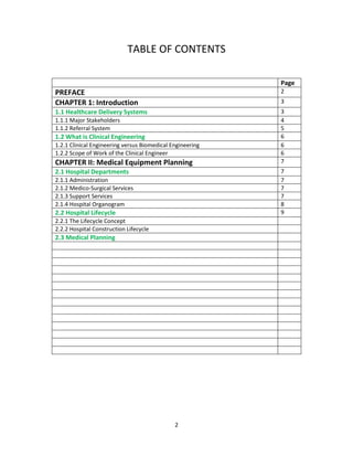
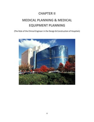
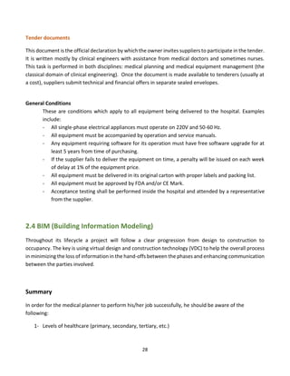
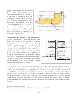
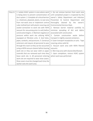
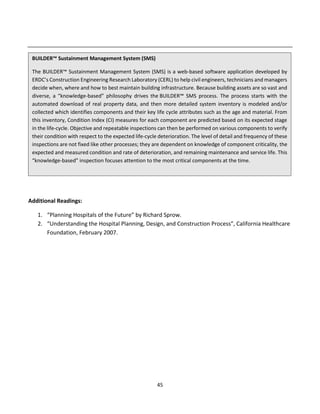
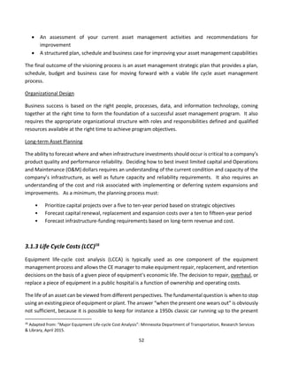
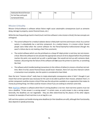
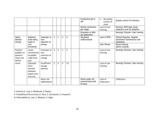
Review Questions
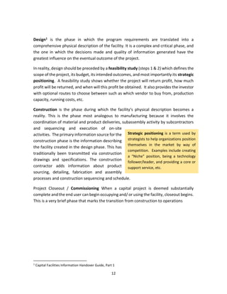
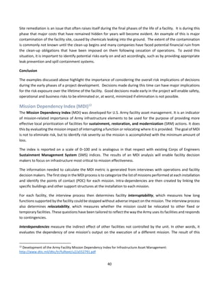
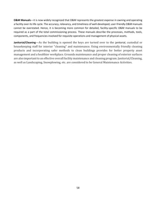
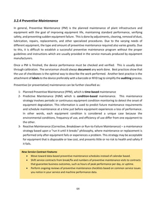
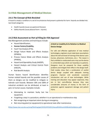
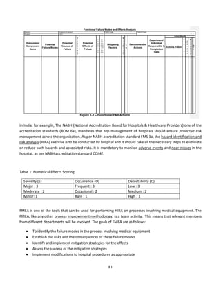
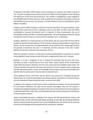
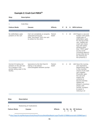
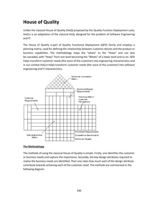
[1] An interstitial floor is one which is sandwiched between two floors with about half the
regular height. It is used to accommodate all sorts of infrastructure components such as
ventilation pipes.
(a) Which hospital department benefits the most from interstitial floors?
(b) What other services can be provided by the interstitial floor?
(c) Would you consider an interstitial floor as a micro or macro level adaptability?
Why?
(d) Show where in this drawing would interstitial space exist.
(e) Give an example of the kind of hardware you may find in the interstitial space.
(f) From the engineering drawing point of view, give an appropriate name for
this section.
(g) From the medical planning point of view, give an appropriate name for this
kind of drawing.
(h) Suggest names for the other (non-interstitial) spaces by writing them on the
figure. Explain your choices. [4 points]
(i) Make a room-by-room list for the non-interstitial spaces. Make any
REASONABLE assumptions.](https://image.slidesharecdn.com/clinicalengineeringprinciples-2018-200816181850/85/Clinical-engineering-principles-2018-16-320.jpg)

![21
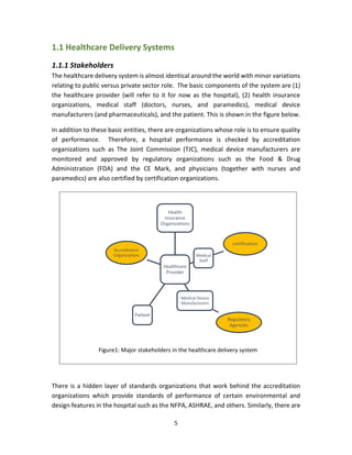
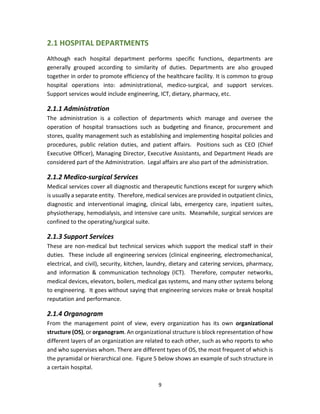
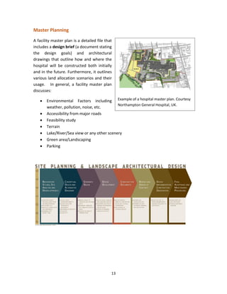
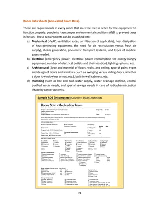
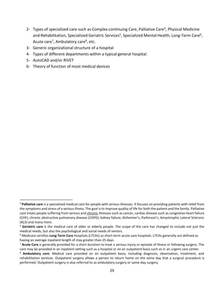
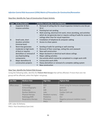
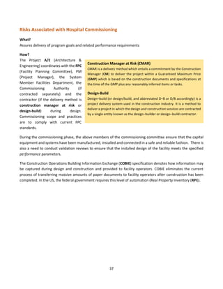
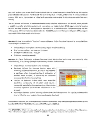
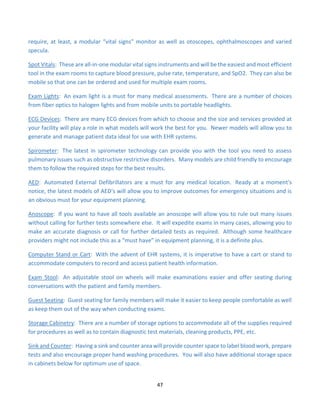
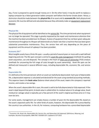
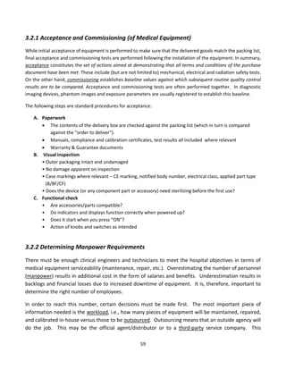
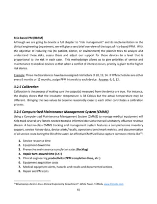
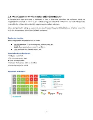
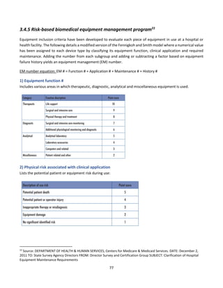
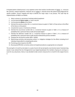
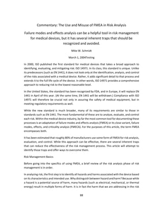
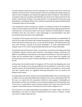
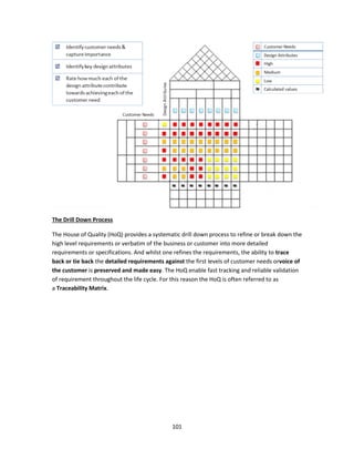
Definitions:
[Source: http://edissues.wikidot.com/estimating-
departmental-gross-square-footage ]
Net Square Feet (NSF): The space within the walls of a
room or the usable floor area assigned to a function in
an open area, e.g., cubicles or workstations. The space
includes casework, fixtures and door swings but does
not include wall thicknesses.
Departmental Gross Square Feet (DGSF): the space
inside the centerline of the walls separating a
department from adjoining areas; includes internal
walls, corridors, etc.
Building Gross Square Feet (BGSF): It is the total area of
the facility including outside walls, mechanical spaces
and canopies.
Net to Gross Factor or Grossing Factor: It is a multiplication factor applied to space to increase the
allotment to accommodate elements not in the base number. A grossing factor is applied to space
lists on Net Square feet to take into account internal circulation and walls to give Departmental
Gross Square Feet (DGSF). Another factor is used to increase DGSF to Building Gross Square Feet
(BGSF) and estimate the amount required for major vertical circulation, shafts and building
circulation. As a rule of thumb, building gross is approximately twice the amount of net area in a
hospital.](https://image.slidesharecdn.com/clinicalengineeringprinciples-2018-200816181850/85/Clinical-engineering-principles-2018-21-320.jpg)
![43
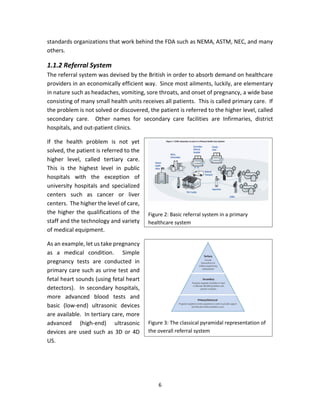
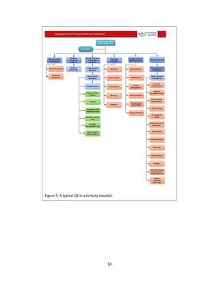
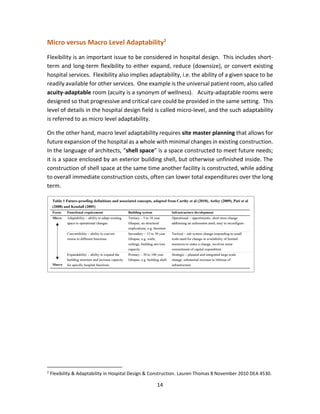
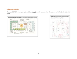
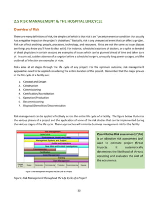
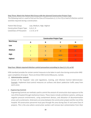
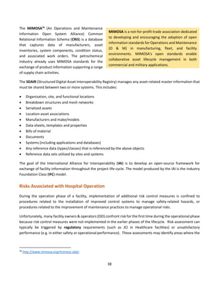
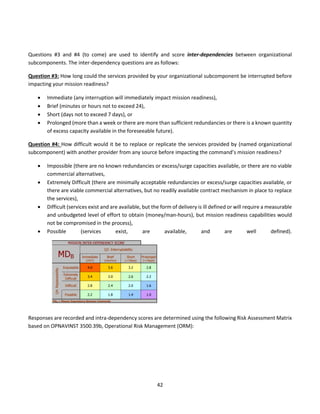
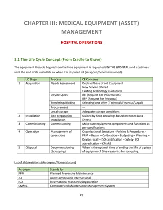
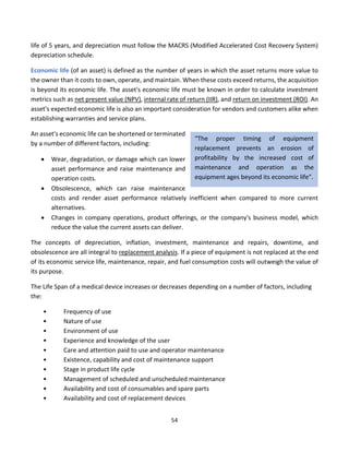
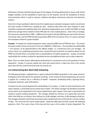
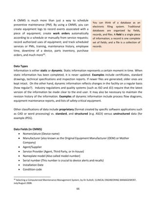
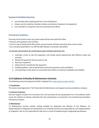
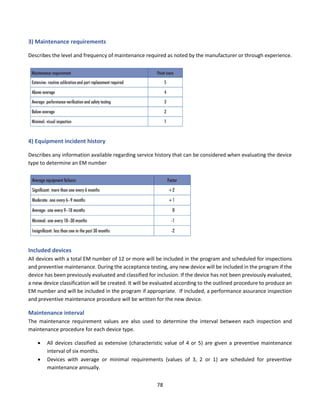
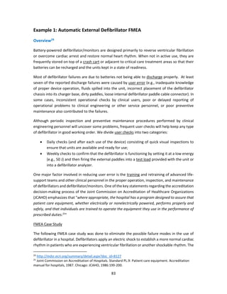
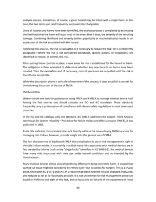
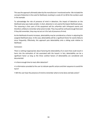
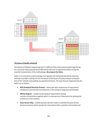
Calculating the MDI score
The scoring matrices shown in Tables 1 and 2 are used in conjunction with the MDI algorithm to calculate the MDI
score. Using a matrix to quantify and prioritize risk severity does not eliminate the inherently subjective nature of
risk assessment; however, a matrix does provide a consistent framework for evaluating risk.
The MDI is calculated using an equation with three coefficients. The MD(Within) and MD(Between) scores are a
resultant of the matrices used in the intra and inter- dependency lines of question. The third input is the number
(n) of other subcomponents recognizing the subject subcomponent as a mission critical service provider. The
following MDI equation and weighted coefficients are the result of three years of extensive field-testing by Navy,
Coast Guard and NASA facility engineers and managers:
MDI = [MD(Within) + *MD(Between Average) + Ln(n)] –
Where:
• MDI = Mission Dependency Index normalized from zero to 100
• MD(Within) = Intra-dependency Score; response to questions 1 and 2 (see Table 1)
• MD(Between) = (Interdependency Score): The average response to questions 3 and 4, (see Table 2)
• Ln( ) = natural log function
• n = number of Interdependencies with other Functional Areas
The natural log function is used because the difference between 1 and 2 is much more relevant than the difference
between 11 and 12.
The MDI color code and nomenclature used is as follows:
Scoring is divided into five categories with a 15 point spread separating critical, significant, relevant, moderate,
and low. The MDI equation is weighted to allow functional elements with high inter-dependency scores to move
up to the next level of criticality. The exception is functional elements with very low intra-dependency scores (less
than 25).
The MDI has been recognized by the US General Services Administration in 2003 as a “Best Practice” and by the
Federal Facilities Council (Cable and Davis 2005) as “a promising process indicator for prioritizing projects and
funding to support an organization’s overall mission”. When combined with other metrics, such as a Condition
Index (CI), MDI can be used to prioritize funding for projects having the most positive impact. MDI is valuable for
prioritizing real property resources in the conduct of facility assessments. In this area, facilities with high MDI](https://image.slidesharecdn.com/clinicalengineeringprinciples-2018-200816181850/85/Clinical-engineering-principles-2018-43-320.jpg)
![46
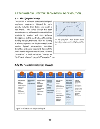
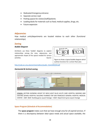
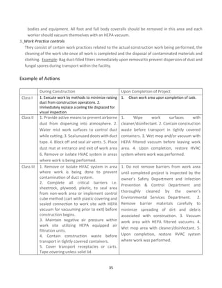
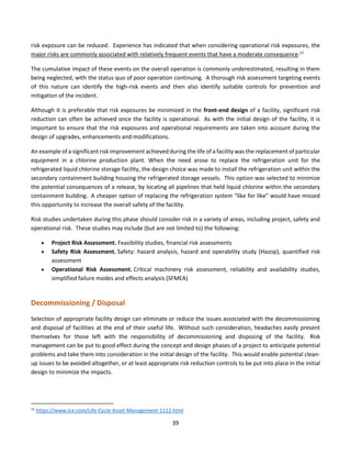
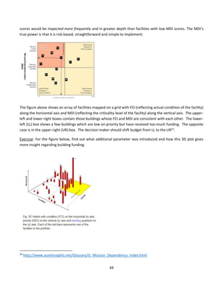
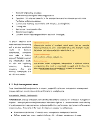
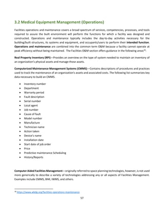
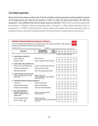
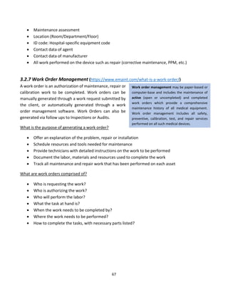
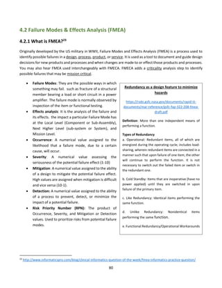
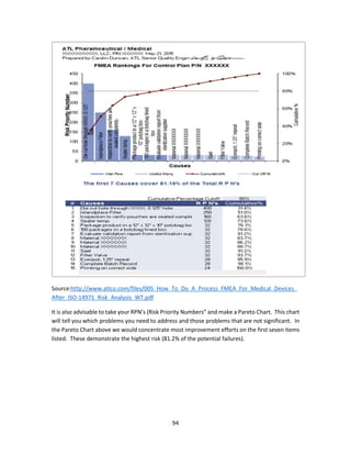
Chapter Questions
[1] Design a minor operating room and its related services following the steps discussed in this
chapter.
Hint
In the concept design phase, we should describe the design requirements in a general but definite way.
First, we must define what is meant by minor surgery. A minor surgery is a surgical procedure that does
not require general anesthetic such as:
Main Category Operations
Injections intra-articular, peri-articular, varicose veins, haemorrhoids
Aspirations joints, cysts, bursae, hydrocele
Incisions abscesses, cysts, thrombosed piles
Excisions sebaceous cysts, lipoma, warts, skin lesions for histology, intradermal naevi,
papilloma,
dermatofibroma and similar lesions, removal of toenails
Curette, cautery and
cryo-cautery
warts and verrucae, other skin lesions (skin surgery) (e.g. molluscum
contagiosum)
Other removal of foreign bodies, nasal cautery
Second, these procedures should be mapped into services and medical equipment.
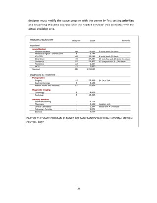
[2] Make a room-by-room list of a typical Examination Room in the Outpatient Clinic
Answer
Exam Table: An adjustable exam table, ideally with cabinets and storage beneath, is an absolute “must
have” and will provide a place to examine patients while also providing much needed storage without
taking up extra floor space. There are many new laws in the works that address the ADA (Americans
with Disabilities Act). A power exam table that goes as low as 18” should be considered. Not only will it
be ADA friendly, but could increase the workflow of an office, allowing more patients to be seen in a day.
Integrated Diagnostic System: An integrated diagnostic system provides you everything you will require
for a basic examination. You will be able to perform checks using an ophthalmoscope, otoscope,
sphygmomanometer, and an electronic thermometer. Having a wall-mounted diagnostic system will
keep everything you need for the medical exam at arms-reach, as well as keeping everything charged so
you never have to worry about having your equipment fail while you are mid-exam. If wall space is
limited you can also consider a wall-mounted transformer with heads that can be switched up as
required based on the patient’s needs. If you cannot accommodate an integrated system you will](https://image.slidesharecdn.com/clinicalengineeringprinciples-2018-200816181850/85/Clinical-engineering-principles-2018-46-320.jpg)

![50
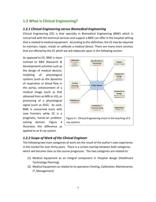
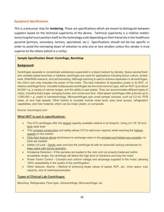
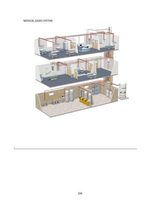
3.1.1 Overview
Life Cycle Asset Management (LCAM) (also called Enterprise Asset Management, EAM15) is an integrated
approach to optimizing the life cycle of assets beginning with user requirements specifications,
continuing through operation and decommissioning. Thorough planning, analysis and timely execution
allow appropriate data-driven decision-making to occur and enable LCAM to deliver optimum:
• Operating and maintenance strategies
• Organizational structure
• Staffing requirements
• Optimized PM/PdM (Preventive & Predictive Maintenance) procedures
15
Enterprise asset management software is a computer software that handles every aspect of running a modern public works
or asset-intensive organization. Effective enterprise asset management (EAM) software solutions include many powerful
features, such as complete asset life-cycle management, flexible preventive maintenance scheduling, complete warranty
management, integrated mobile wireless handheld options and portal-based software interface. [2] Rapid development and
availability of mobile devices also affected EAM software which now often supports Mobile enterprise asset management.
(WIKI)
The above figure obtained from the website of Steris Corporation (a company specialized in the production of sterilizers)
life cycle representation covers BOTH equipment production in the factory AND equipment acquisition in the hospital. In
this course, we separate the two environments of the factory and the hospital in order for the student to grasp the concept
and know how to apply it to the relevant working environment.](https://image.slidesharecdn.com/clinicalengineeringprinciples-2018-200816181850/85/Clinical-engineering-principles-2018-50-320.jpg)

![56
Other related financial terms
1- Fixed Cost (Capital cost)
It is a cost that remains the same and does not depend on the amount of goods and services a company
produces. Examples: purchasing price of equipment, apartment rent, and store rent, etc.
2- Variable Cost
It is a cost that varies as the amount of goods and services a company produces varies. A variable cost
is dependent on a company's production volume. Variable Costs include indirect overhead costs such
as Cell Phone Services, Computer Supplies, Credit Card Processing, Electrical use, Janitorial Supplies,
MRO, Office Products, Payroll Services, Telecom, Uniforms, Utilities, or Waste Disposal etc. (WiKi)
3- Asset
A resource with economic value that an individual, corporation or country owns or controls with the
expectation that it will provide future benefit. In the context of accounting, assets are either current
or fixed (non-current). Current means that the asset will be consumed within one year. Generally, this
includes things like cash, accounts receivable and inventory. Fixed assets are those that are expected
to keep providing benefit for more than one year, such as equipment, buildings and real estate.
4- Net present value (NPV)
PV = FV / (1+r)n
where
PV is Present Value, FV is Future Value, r is the interest rate (as a decimal, so 0.10, not 10%),
and n is the number of years.
[Source: http://www.mathsisfun.com/money/net-present-value.html]
5- Internal rate of return (IIR)
6- Return on investment (ROI)](https://image.slidesharecdn.com/clinicalengineeringprinciples-2018-200816181850/85/Clinical-engineering-principles-2018-56-320.jpg)
![61
value in each cell of the matrix is the number of days. For example, the value in cell (1,1) is 3, meaning
that between midnight and 1:00 am no teams were needed for three days.]](https://image.slidesharecdn.com/clinicalengineeringprinciples-2018-200816181850/85/Clinical-engineering-principles-2018-61-320.jpg)

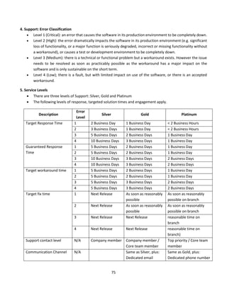

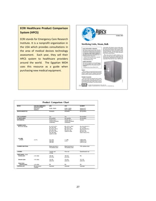
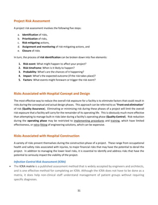
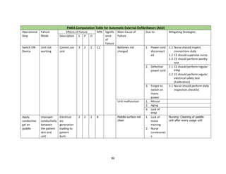
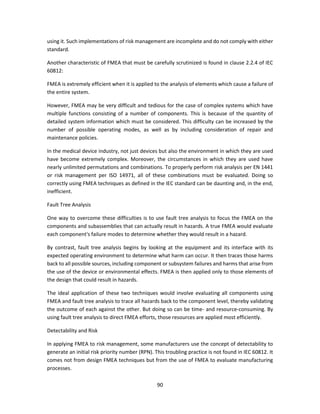
![84
defibrillator is a lifesaving equipment used in emergency situations and any failure/ wrong use
while applying electric shock can lead to first or second degree burns or death of the patient.
The process of using a defibrillator with an external paddle whenever code blue is initiated in a
hospital is shown in the FMEA computation table. The failure mode for each sub process is
tabulated along with effect of each failure, its severity, occurrence and detectability. The possible
cause of failure and mitigating strategies is also filled. The rating for S, O and D are fixed based on
detailed brainstorming session between nursing team, clinicians, head of emergency department
and clinical engineering. The risk priority number for each failure is calculated to understand
which sub process needs priority focus. As we can notice, the following sub process needs
improvements.
1) Switching on defibrillator
2) Positioning of paddles on patient chest and deliver shock
6) Application of conductive gel on paddle
The team assigned the relevant members to work on mitigating strategy. The hospital team, based
on FMEA study, revisited process on maintenance of life saving equipment including defibrillator
and improved on timely preventive maintenance and calibration. The frequency of training and
visual inspection process during daily rounds also increased. The team decided to review the sub
process again after three months, based on the corrective action taken and to revisit the RPN
number. The RPN score for step 1, 2 and 6 came down to 6, 4 and 8 respectively, after
implementing the corrective measures on ground.
The FMEA for defibrillator helped the organisation to strengthen internal processes and to avoid
the potential defect in process, which could have affected patient care. Similar studies can be
done in other areas where medical equipment is involved, as part of the HIRA exercise.
UMDNS Terms
• Defibrillator/Monitors [11-129]
• Defibrillator/Monitors, Line Powered [15-029]
• Defibrillators, Battery Powered [11-134]
• Defibrillators, Line Powered [11-137]
Causes of Device-Related Incident
Device factors:
Improper maintenance, testing, repair, or lack or failure of incoming inspection; Random
component failure](https://image.slidesharecdn.com/clinicalengineeringprinciples-2018-200816181850/85/Clinical-engineering-principles-2018-84-320.jpg)


The document discusses clinical engineering principles and medical equipment planning. It begins with an introduction to healthcare delivery systems and key stakeholders. Clinical engineering is defined as the specialty within biomedical engineering focused on technical services and support related to medical equipment in hospitals. The scope of clinical engineering work includes medical equipment planning during hospital design and equipment operation activities like testing, calibration and maintenance. The document then covers hospital departments and how they are typically grouped, as well as the organizational structure and lifecycle of hospitals. Medical equipment planning is part of the role of clinical engineers in the design and construction of new healthcare facilities.


